
CIVE 210 Chapter 6, Spring 2017
American University of Beirut · Statics · 17 pages
Showing the first 10 of 17 pages. Download the PDF to see all of it.
More CIVE 210 files
- Syllabus · Spring 2019LabView
- Exam 1 · Fall 2018ExamView
- Exam 2 QUIZ 2 · Spring 2017ExamView
- Homework HW 3 · Spring 2017HomeworkView
- Homework Hw 4 Solution · Spring 2017Homework · with solutionView
- Homework Hw 1 Solution Spring 2017 · Spring 2017Homework · with solutionView
- Exam 2 Spring 15-16 · Spring 2016ExamView
- Syllabus · Fall 2016LabView
Show the text of this chapter
1/11/2013
Chapter 6 - Structural Analysis
1
STATICS: CE201
Chapter 6
Structural Analysis
Notes are prepared based on: Engineering Mechanics, Statics by R. C. Hibbeler, 12E Pearson
Dr M. Touahmia & Dr M. Boukendakdji
Civil Engineering Department, University of Hail
(2012/2013)
1
Chapter 6 -Structural Analysis
6. Structural Analysis
________________________________________________________________________________________________________________________________________________
Main Goal:
To show how to determine the forces in the members of a
truss using the method of joints and the method of section.
Contents:
6.1
Simple Trusses
6.2
The Method of Joints
6.3
Zero Force Members
6.4
The Method of Sections
2
Chapter 6 -Structural Analysis
1/11/2013
Chapter 6 - Structural Analysis
2
6.1
Simple Trusses
A truss is a structure composed of slender members
joined together at their end points.
The members are usually wooden struts or metal bars.
Planar trusses lie in a single plane and are often used to
support roofs and bridges.
The roof load is transmitted to the truss at the joints by
means of a series of purlins.
3
Chapter 6 -Structural Analysis
6.1
Simple Trusses
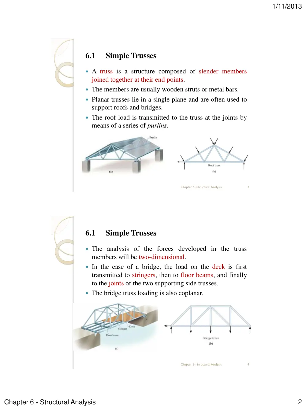
The analysis of the forces developed in the truss
members will be two-dimensional.
In the case of a bridge, the load on the deck is first
transmitted to stringers, then to floor beams, and finally
to the joints of the two supporting side trusses.
The bridge truss loading is also coplanar.
4
Chapter 6 -Structural Analysis
1/11/2013
Chapter 6 - Structural Analysis
3
6.1
Simple Trusses
Assumption for Design:
To design both the members and the connections of a
truss, it is necessary first to determine the force
developed in each member when the truss is subjected to
a given loading.
Each truss member is considered as a two-force member
so that the forces at the ends of the member must be
directed along the axis of the member.
All loadings are applied at the joints.
The members are joined together by smooth pins.
5
Chapter 6 -Structural Analysis
6.1
Simple Trusses
Assumption for Design:
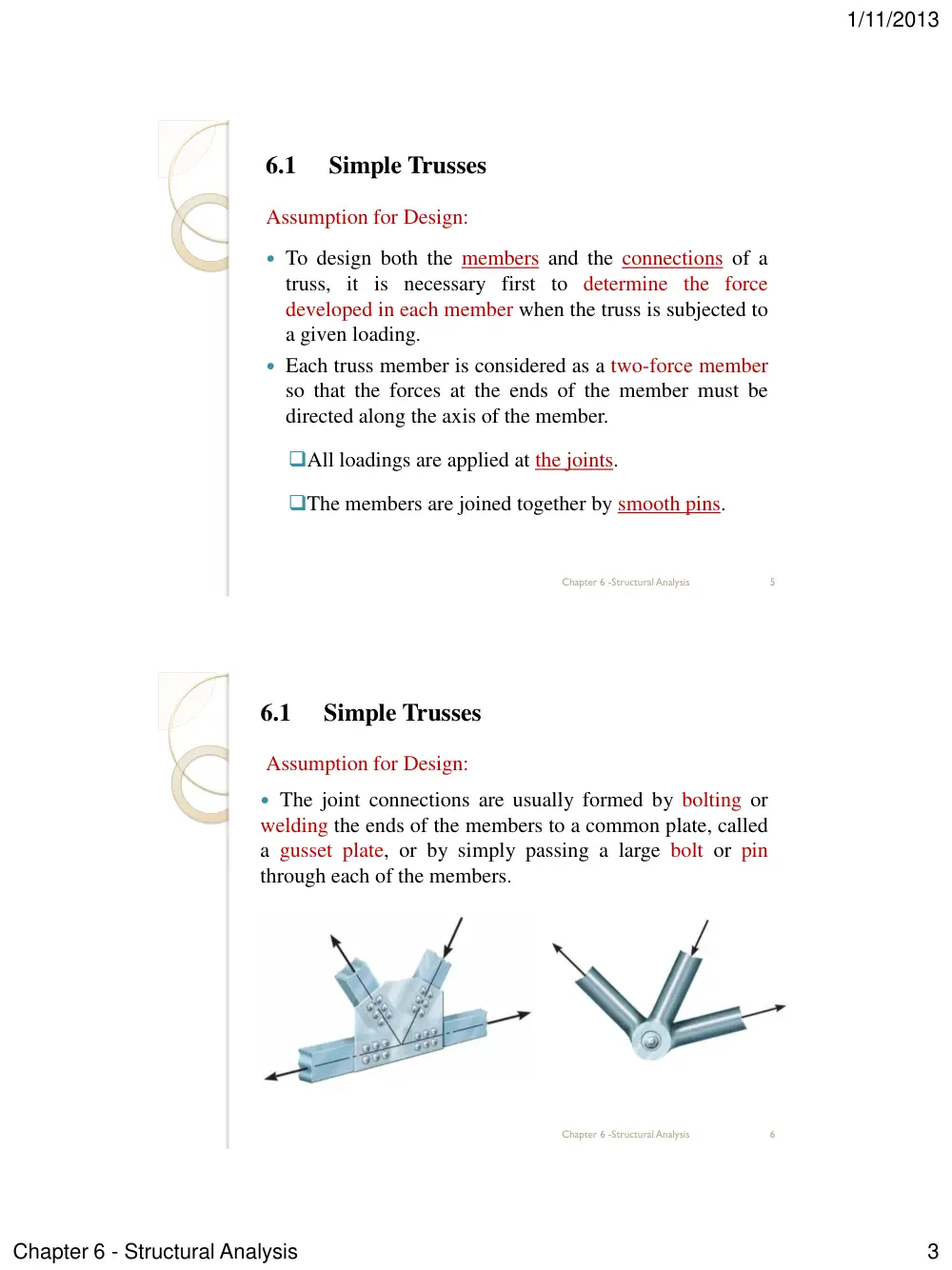
The joint connections are usually formed by bolting or
welding the ends of the members to a common plate, called
a gusset plate, or by simply passing a large bolt or pin
through each of the members.
6
Chapter 6 -Structural Analysis
1/11/2013
Chapter 6 - Structural Analysis
4
6.1
Simple Trusses
Assumption for Design:
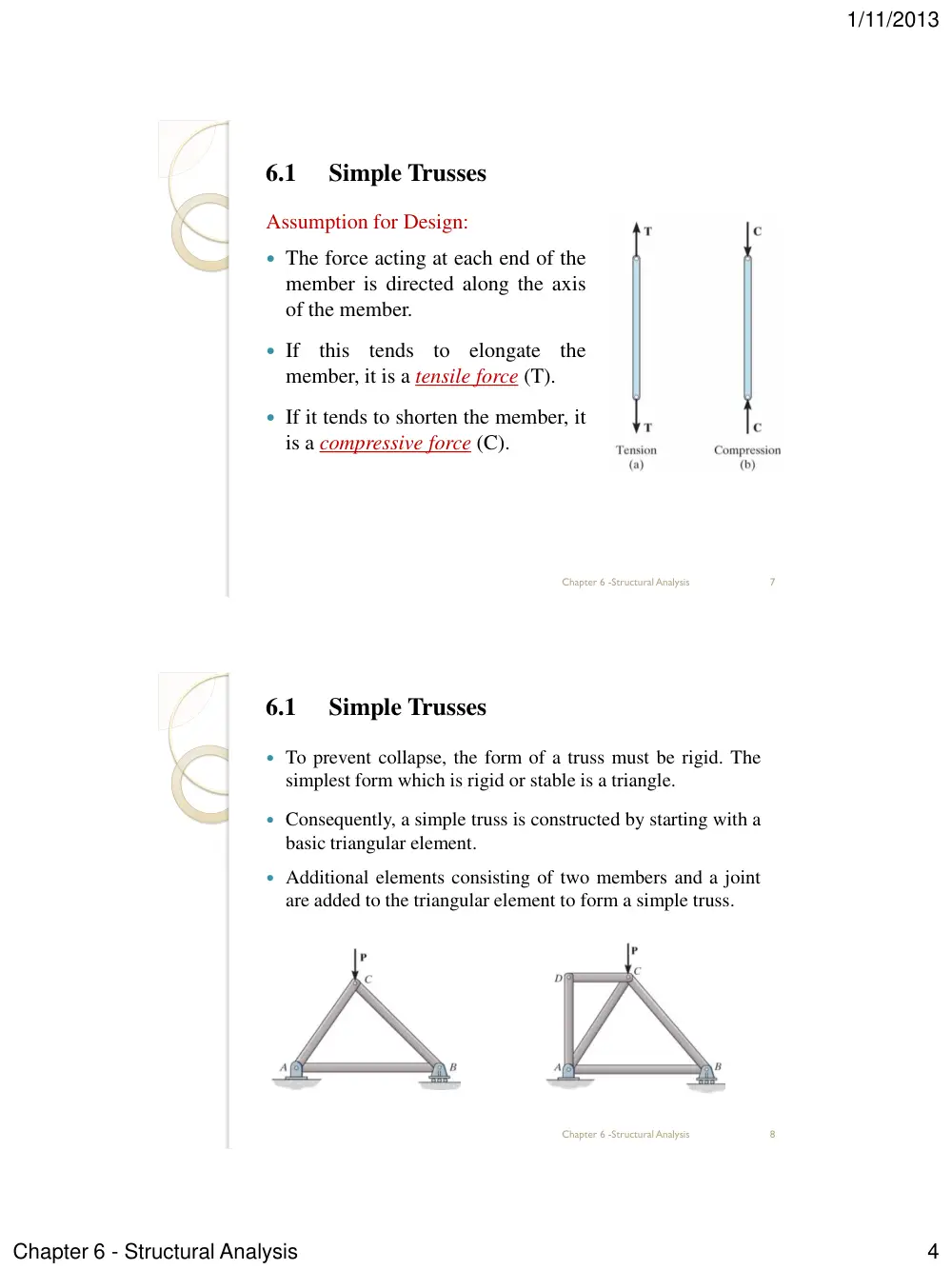
The force acting at each end of the
member is directed along the axis
of the member.
If this tends to elongate the
member, it is a tensile force (T).
If it tends to shorten the member, it
is a compressive force (C).
7
Chapter 6 -Structural Analysis
6.1
Simple Trusses
To prevent collapse, the form of a truss must be rigid. The
simplest form which is rigid or stable is a triangle.
Consequently, a simple truss is constructed by starting with a
basic triangular element.
Additional elements consisting of two members and a joint
are added to the triangular element to form a simple truss.
8
Chapter 6 -Structural Analysis
1/11/2013
Chapter 6 - Structural Analysis
5
6.2
The Method of Joints
The method of joint is based on the fact that if the entire
truss is in equilibrium, then each of its joints is also in
equilibrium.
Therefore, if the free-body diagram of each joint is drawn,
the force equilibrium equations can then be used to obtain
the member forces acting on each joint.
Since the members of a plane truss are straight two-force
members lying in a single plane, each joint is subjected to a
force system that is coplanar and concurrent.
As a result, and need to be satisfied
for equilibrium.
9
Chapter 6 -Structural Analysis
0
Fx
0
y
F
6.2
The Method of Joints
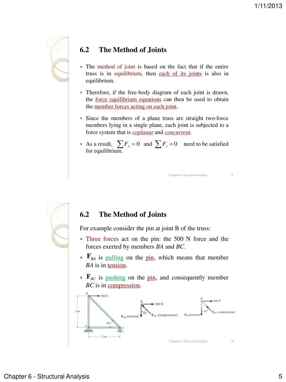
For example consider the pin at joint B of the truss:
Three forces act on the pin: the 500 N force and the
forces exerted by members BA and BC.
is pulling on the pin, which means that member
BA is in tension.
is pushing on the pin, and consequently member
BC is in compression.
10
Chapter 6 -Structural Analysis
BA
F
FBC
1/11/2013
Chapter 6 - Structural Analysis
6
6.2
The Method of Joints
When using the method of joints, always start at a joint
having at least one known force and at most two
unknown forces.
and can be solved to determine the
two unknowns.
The correct sense of an unknown member force can be
determined using one of two possible methods:
The correct sense of direction of an unknown member
force can be determined by inspection.
Assume the unknown member forces acting on the
joint’s free-body diagram to be in tension.
11
Chapter 6 -Structural Analysis
0
Fx
0
y
F
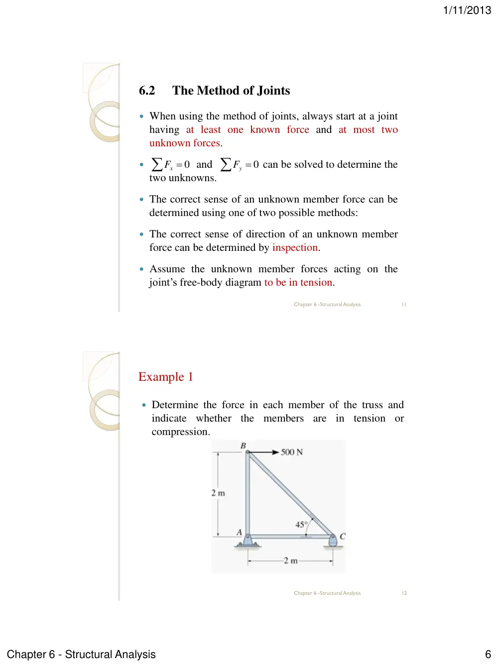
Example 1
Determine the force in each member of the truss and
indicate whether the members are in tension or
compression.
12
Chapter 6 -Structural Analysis
1/11/2013
Chapter 6 - Structural Analysis
7
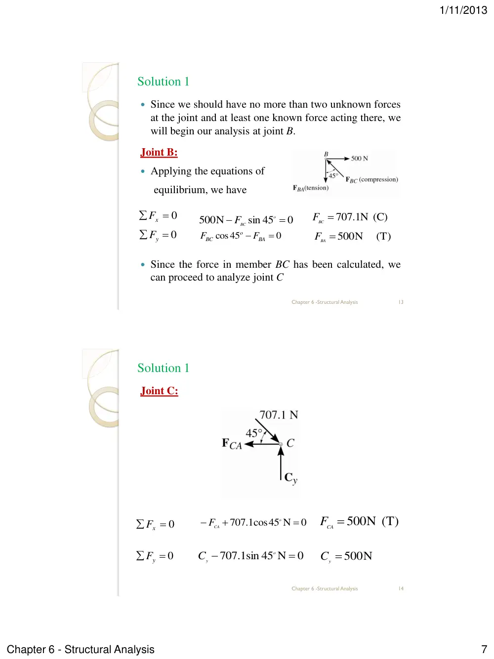
Solution 1
Since we should have no more than two unknown forces
at the joint and at least one known force acting there, we
will begin our analysis at joint B.
Joint B:
Applying the equations of
equilibrium, we have
Since the force in member BC has been calculated, we
can proceed to analyze joint C
13
Chapter 6 -Structural Analysis
0
Fx
0
sin 45
500N
o
FBC
BC 707 1. N (C)
F
0
Fy
0
cos45
BA
o
BC
F
F
(T)
BA 500N
F
Solution 1
Joint C:
14
Chapter 6 -Structural Analysis
0
Fx
CA 500N (T)
F
0
Fy
y 500N
C
0
707 1. cos45 N
o
CA
F
0
707 1. sin 45 N
o
Cy
1/11/2013
Chapter 6 - Structural Analysis
8
Solution 1
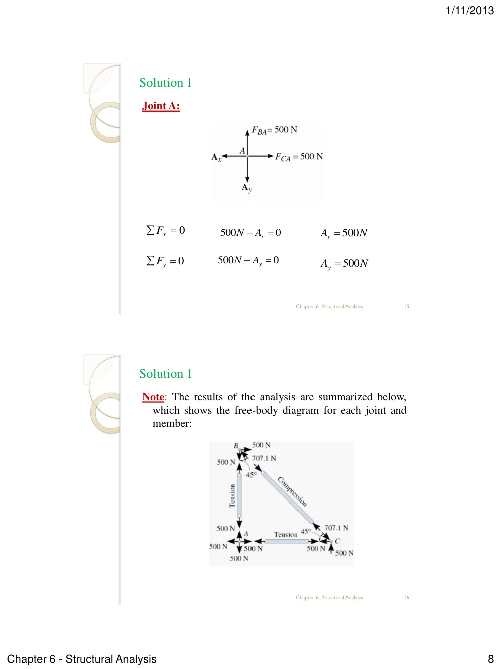
Joint A:
15
Chapter 6 -Structural Analysis
0
500
Ax
N
0
x
F
0
y
F
N
Ax
500
0
500
Ay
N
N
Ay
500
Solution 1
Note: The results of the analysis are summarized below,
which shows the free-body diagram for each joint and
member:
16
Chapter 6 -Structural Analysis
1/11/2013
Chapter 6 - Structural Analysis
9
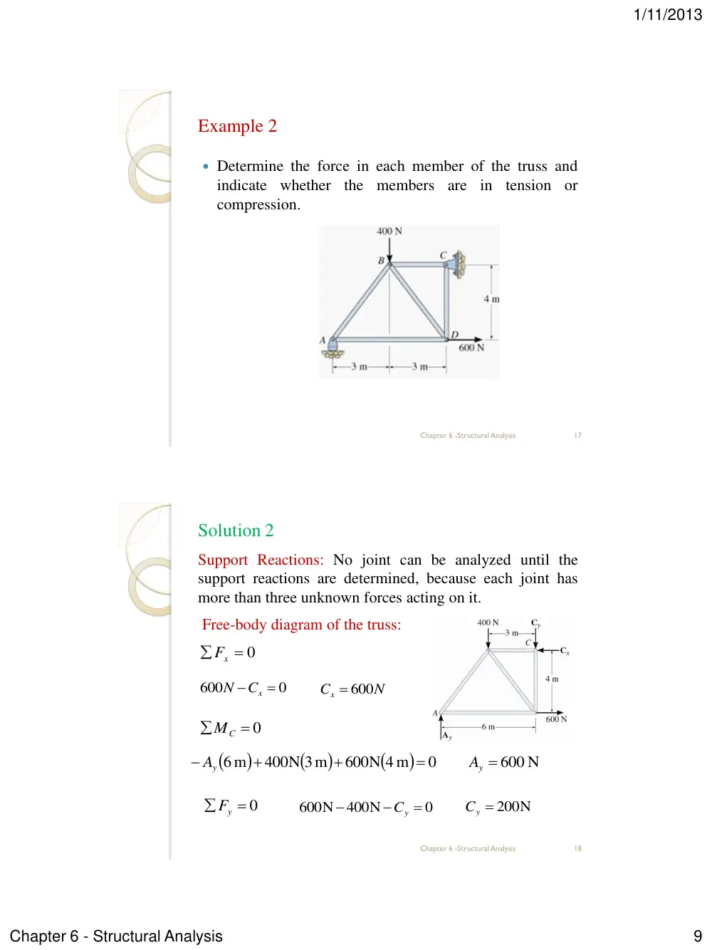
Example 2
Determine the force in each member of the truss and
indicate whether the members are in tension or
compression.
17
Chapter 6 -Structural Analysis
Solution 2
Support Reactions: No joint can be analyzed until the
support reactions are determined, because each joint has
more than three unknown forces acting on it.
Free-body diagram of the truss:
18
Chapter 6 -Structural Analysis
0
x
F
0
600
Cx
N
y 600 N
A
0
y
F
N
Cx
600
0
C
M
0
600N 4 m
400N 3m
6 m
y
A
0
400N
600N
Cy
Cy 200N
1/11/2013
Chapter 6 - Structural Analysis
10
Solution 2
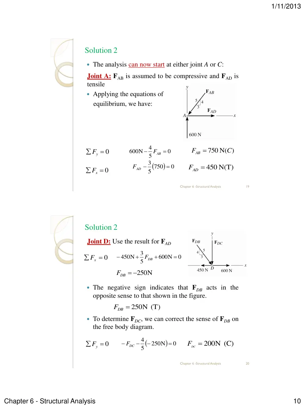
The analysis can now start at either joint A or C:
Joint A: FAB is assumed to be compressive and FAD is
tensile
Applying the equations of
equilibrium, we have:
19
Chapter 6 -Structural Analysis
0
Fy
750 N( )
C
FAB
0
Fx
AD 450 N(T)
F
0
5
4
600N
AB
F
0
5 750
3
AD
F
Solution 2
Joint D: Use the result for FAD
The negative sign indicates that FDB acts in the
opposite sense to that shown in the figure.
To determine FDC, we can correct the sense of FDB on
the free body diagram.
20
Chapter 6 -Structural Analysis
0
x
F
DB 250N
F
0
y
F
DB 250N (T)
F
0
600N
5
3
450N
DB
F
0
250N
5
4
FDC
FDC 200N (C)
1/11/2013
Chapter 6 - Structural Analysis
11
Solution 2
Joint C:
(Check)
21
Chapter 6 -Structural Analysis
0
x
F
0
y
F
FCB 600N (C)
0
600N
CB
F
0
200N
200N
Solution 2
Note: The analysis is summarized below, which shows
the free-body diagram for each joint and member:
22
Chapter 6 -Structural Analysis
1/11/2013
Chapter 6 - Structural Analysis
12
6.3
Zero-Force Members
The zero-force members of a truss can generally be
found by inspection of each of the joints.
For example, consider the truss below.
At Joint A, it is seen that members AB and AF are zero-
force members:
23
Chapter 6 -Structural Analysis
0
x
F
0
y
F
AB 0
F
AF 0
F
6.3
Zero-Force Members
At Joint D, it is seen that members DC and DE are
zero-force members.
From these observations, we can conclude that if only
two members form a truss joint and no external load or
support reaction is applied to the joint, the two
members must be zero-force members.
24
Chapter 6 -Structural Analysis
0
x
F
0
Fy
0
sin
FDC
DC 0
F
FDE 0
1/11/2013
Chapter 6 - Structural Analysis
13
6.3
Zero-Force Members
Now consider this truss:
At Joint D, it is seen that DA is zero-force member:
25
Chapter 6 -Structural Analysis
0
x
F
0
y
F
DA 0
F
DE
DC
F
F
6.3
Zero-Force Members
At Joint D, it is seen that DA is zero-force member.
In general then, if three members form a truss joint for
which two of the members are collinear, the third
member is a zero-force member provided no external
force or support reaction is applied to the joint.
26
Chapter 6 -Structural Analysis
0
x
F
0
y
F
CA 0
F
CD
CB
F
F
0
sin
FCA
1/11/2013
Chapter 6 - Structural Analysis
14
6.4
The Method of Sections
When we need to find the force in only a few members
of a truss we can analyze the truss using the method of
sections.
This method is based on the principle that if the truss is
in equilibrium then any segment of the truss is also in
equilibrium.
If the forces within the members are to be determined,
then an imaginary section can be used to cut each
member into two parts.
27
Chapter 6 -Structural Analysis
6.4
The Method of Sections
The method of sections can also be used to cut or
section the members of an entire truss.
28
Chapter 6 -Structural Analysis
1/11/2013
Chapter 6 - Structural Analysis
15
6.4
The Method of Sections
For example, consider the truss below:
If the forces in members BC, GC, and GF are to be
determined, then section a-a would be appropriate.
29
Chapter 6 -Structural Analysis
6.4
The Method of Sections
The free-body diagrams of the two segments are then:
Members BC and GC are assumed to be in tension
since they are subjected to a pull, whereas GF in
compression since it is subjected to a push.
30
Chapter 6 -Structural Analysis
1/11/2013
Chapter 6 - Structural Analysis
16
6.4
The Method of Sections
The Three unknown member forces FBC, FGC, and FGF
can be obtained by applying the three equilibrium
equations of the segments.
The three support reactions Dx, Dy and Ex can be
obtained by considering a free-body diagram of the
entire truss.
31
Chapter 6 -Structural Analysis
Example 2
Determine the force in members GE, GC, and BC of the
truss. Indicate whether the members are in tension or
compression.
32
Chapter 6 -Structural Analysis
1/11/2013
Chapter 6 - Structural Analysis
17
Solution 2
Section a-a has been chosen since it cuts through the
three members whose forces are to be determined.
It is first necessary to determine the external reactions at
A and D.
33
Chapter 6 -Structural Analysis
0
Fx
0
400N
x
A
x 400N
A
0
MA
0
12m
400N 3m
1200N 8m
y
D
y 900N
D
0
Fy
0
900N
1200N
Ay
y 300N
A
Solution 2
Free-Body Diagram: For the analysis the free-body diagram of
the left portion of the sectioned truss will be used.
Equations of Equilibrium:
34
Chapter 6 -Structural Analysis
0
G
M
BC 800N (T)
F
0
C
M
0
3m
400N 3m
300N 4m
BC
F
GE 800N (C)
F
0
Fy
0
5
3
300N
FGC
GC 500N (T)
F
0
3m
300N 8m
FGE