
CIVE 340 Midterm CIVE 340, Fall 2008
American University of Beirut · Fluid Mechanics and Laboratory · 9 pages
More CIVE 340 files
Show the text of this exam
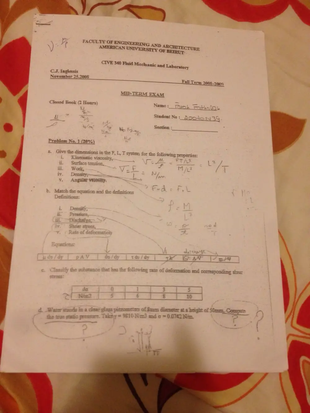
C.J. Ingiessis
November 25.2008
Fall Term 2008-2009
Co Book (2 § : \ ae
josed Boo e Tours) Name :_ k eto
LU R ~ Student No ;
bs om “ky ee Section :__
’ cs Rohe —<$__$____
Problem No. 1 (20%)
a. Give the dimensions in the F, L, T system
for the following Properties:
Kinematic viscosity, ‘ o 4
= A >
cone ¥ L a GRO
ti — Surface:tension, Bias aS ae a 7 =
iii Work, y= + P seed a
iv Density; — H lp
vy. Angular -veleeny,
b. Match the equation and the definitions e-
Definitions
pi
u
;
OT
dy Ko: AAT pi
y the stan vat has the following rate of deformation end corresponding shear
jc
™ N/m? 6
¢giags piczometss of 8mm diameter at 2 height of 50mm. Commut: ~~
Takey = 9810-Nim3 and o = 0.0742 Nim. a: ~ ees of
e {
OF ENGINE
AMERICAN U
ERUNG AND ARCHITECTURE
IVERSITY OF BEIRUT
CIVE 340 Finid Mechanic and Laboratory
Eni! Term 2009-2030
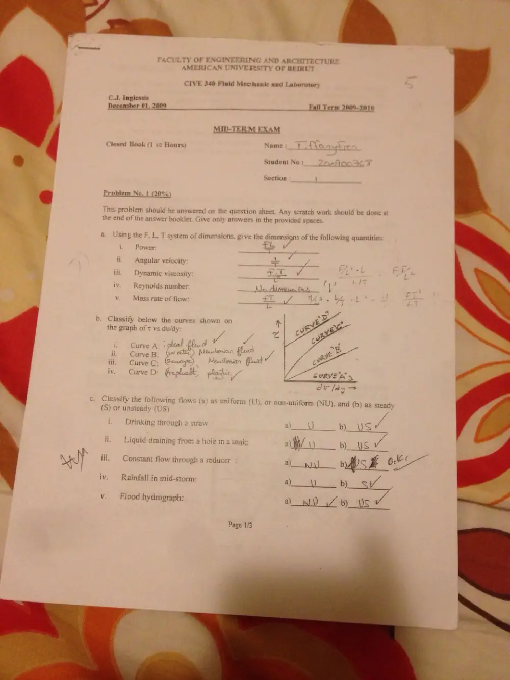
MID-TERM EXAM
Closed Book (1 i2 Hours) Name Li4
Student No Zeachc }
Section
& Problem No. ! (20%)
This problem should be answered on the qu
thi
SStion sh
Any s
1. Give only answers in the provided spaces
end of the answer book
; a. Using the F. L. T system of dimensions, give the dimensions of the following quantitie:
‘ FL
Power
Le
n Angular velocity —
: rT. 1 v
m Vynamic viscosity <——
iv Reynolds numbe: wes ALO eas BA U
v Mass rate of flow / 7
b. Classify below the curves shown on
the graph of t vs du/dy
( A: ot
urve
ii Curve B Bish 2,
iij Vesastanian usd
iv i, plonl
¥
c. Classify the foliowing flows (a) as unif
(S) or un,
eady (US)
Drinking througt raw
ii. Liquid draini om a ht tank:
Nad} iii. Constant flow through a reduce;
iv. Rainfall in mid-storm
tch work should be done a
v. Flood hydrograph:
Page 1/3
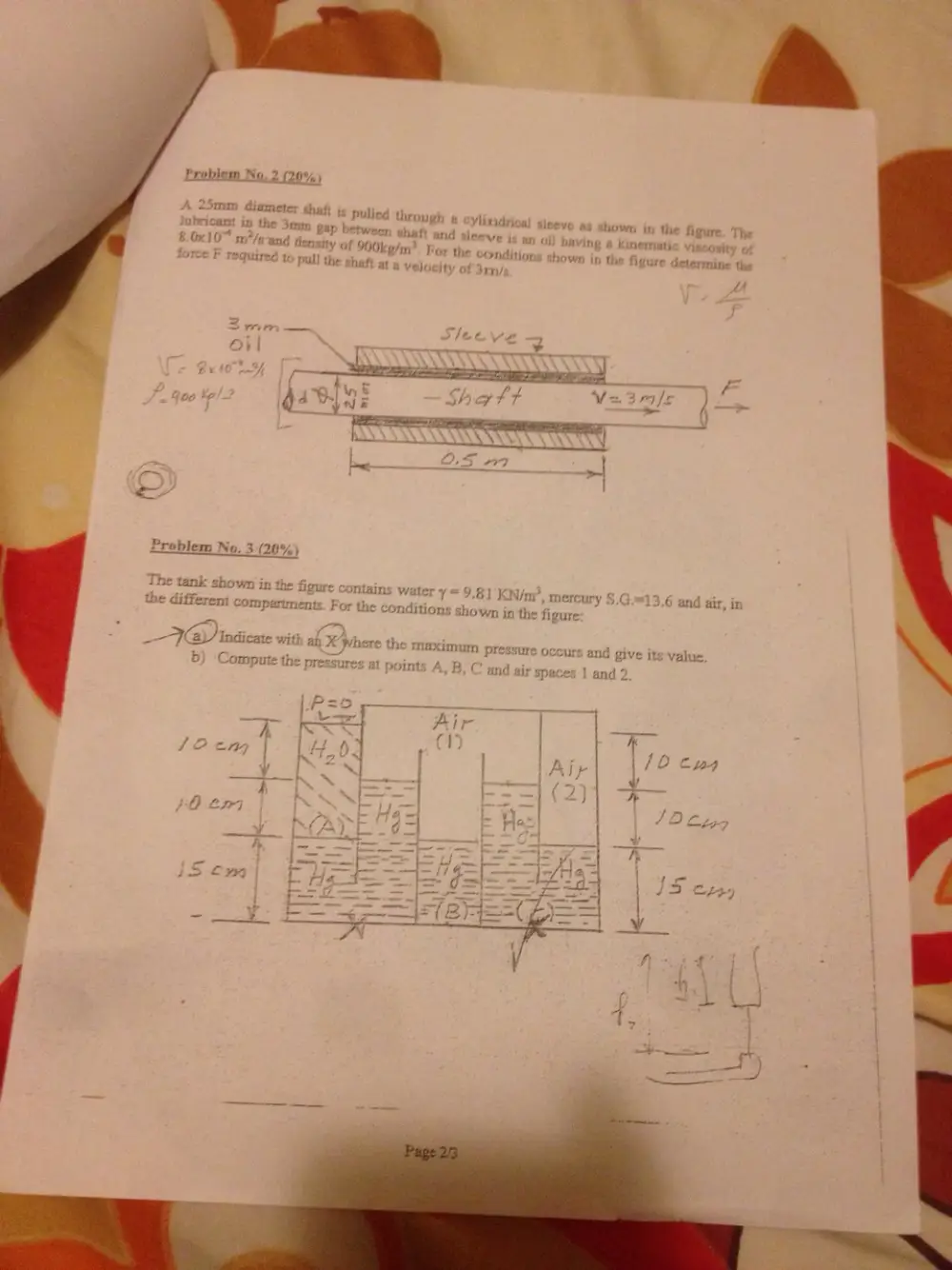
Problem No. 2 (20%
ameter shaft
abricam in the
8.0x10% m/e
pulled through a
D gap between shaft
and density of 900k g/
required to py} the a}
Ylinidrica) siseve
and sleeve js
48 shown in the figure, The
an oi) having « kinemati
m”. For the cond
itions showr
n the figure determine the
Velocity of 3rn/<
tA
Problem No. 3 (20%
em No. 5 (20%)
ye)
¢ figure contains water ¥=9.81K
W/m", x
»-G.=13,6 and air, in
conditions showr
1 in the figure
2 FIG) indicate with an >
imum pressure occ
>) ‘Comput
ad give its value,
o
and
Spaces ] and 2
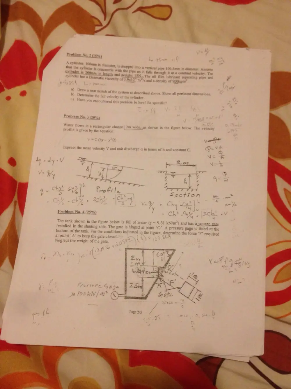
A cylinder, 100mm in dia
cylinder js
\evlinder js
ter, is dropped inte a ne 100.4 i = ~
that the Pr 8 vertical pipe 100.5mm in diamet
“oncentric with the pipe as it fall through
200; @! 4 constant locity
Viinder een lengthy, and iw N.y The oi! film lubricant separating pipe ar 2
incer has a kinematic viscosity of 3.93107 mr wad & Gonsiey of S0ticate
i the cylinder
Vat as f Hann nm Wide, a hown in the figure bel it
rofile is given by th
l (hy ) ¥
o ;
) w the mean velocity \V aischarge q in terms of h and . P| ~
} wv
The tank shown in the
installed in the slanting
bottom of the tank. For the «
at point “A op t
N the weight of
a4
gate is ] m wide (into
water depth is
For the conditions ind,
to start opening
Neglect the weight of
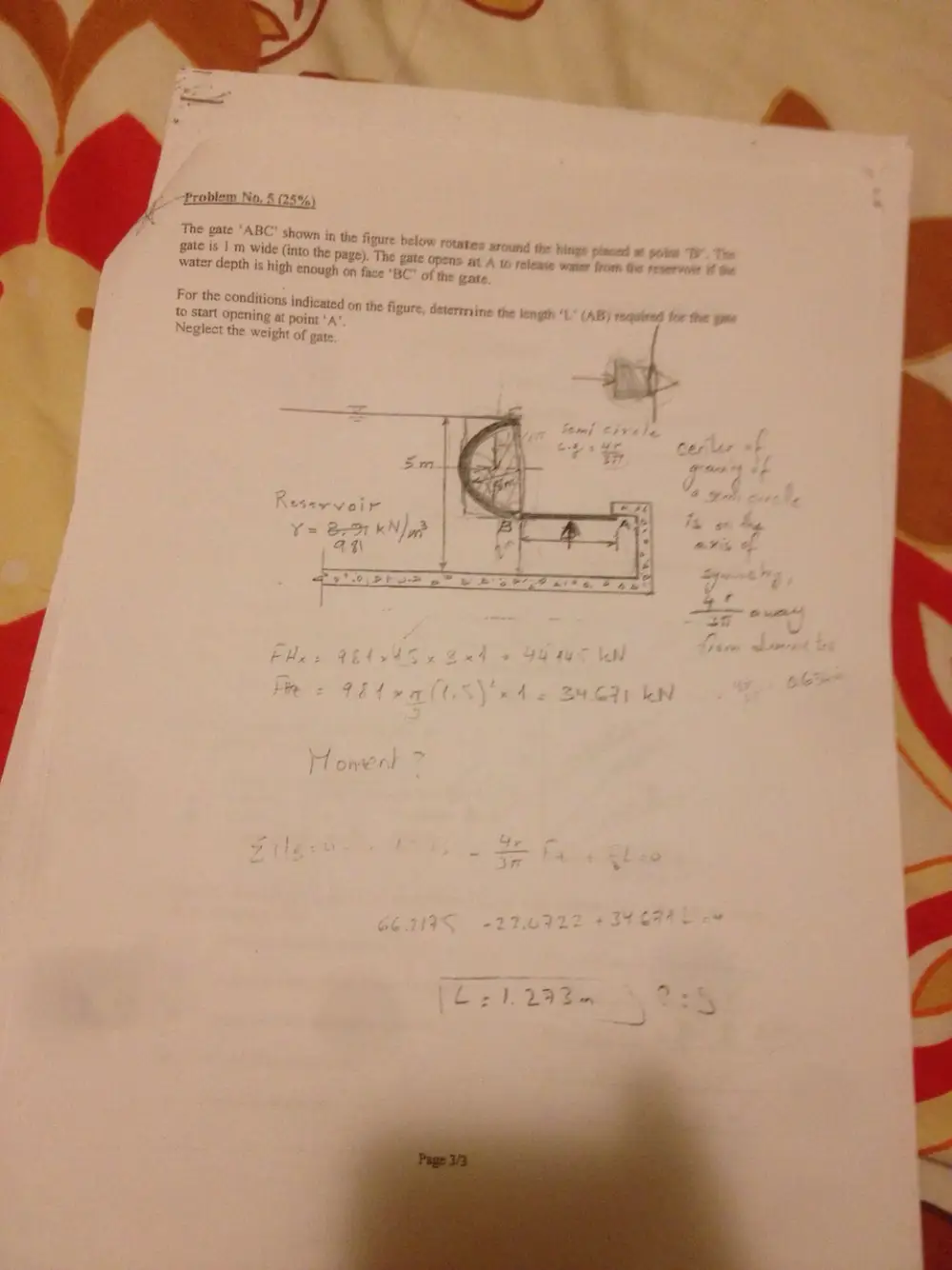
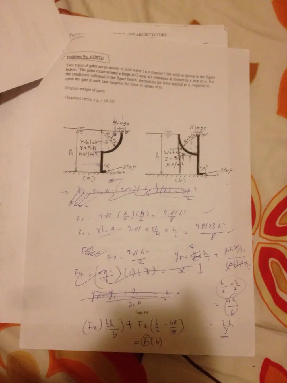
Problem No, 5 25%
The gate ‘ABC’ shown in
the page
Icated on the figure
at point ‘A’
gate
the figure below re
). The gate opens at A
high enough on face ‘BC*
rotates around the hinge placed at ox
10 release water from the reservene ¥
of the gate
determine the length “
>
fe
OF is
r
4
/ 4 — a!
7 aye
Te ep We, Be :
Lo" = — rn
To la ee
recture
, G AND ARCHIT?
ay ae att TV OF ENGINEERING eee WERRUT
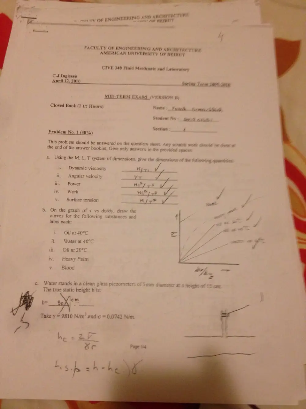
FACULTY OF ENGINEERING AND ARCHITEC Tine
AMERICAN UNIVERSITY OF RETRY r
CIVE 340 Finid Mechanic and Laboratory
CuLInglessis
April 12, 2010 tarred Spring T erm 200° 200
MID-TERM EXAM (VERSION fy
Closed Book (1 12 Hours) Name : Faiah... tamecteioth
Stadem No BOE Nie
Section 7
Problem No. 1 (40%)
This problem should be answered on the question sheet
Any scratch work showld he doce
the end of the answer booklet, Give only answer
s in the provided space
a. Using the M, L, T system of dimensions. give the dimensions of the ONowing anaritities
i. Dynamic viscosity 4 fee A
ii. Angular velocity Yr dh
iii. Power Hy +? Ly
iv. Work —__ if 23 wt
v. Surface tension ace ee engl f
b. On the graph of t vs du/dy. draw the : ad
curves for the following s ces and 1B " y
label each: r J
i. Oil at 40°C * call P
at a
ii Water at 40°C
iii. Oil at 20°C
iv. Heavy Pain ‘ZZ
V Blood oY, " —
=
c. Water stands in a clean glass piezometer mm diameter at ¢ height of os
The true static height h is
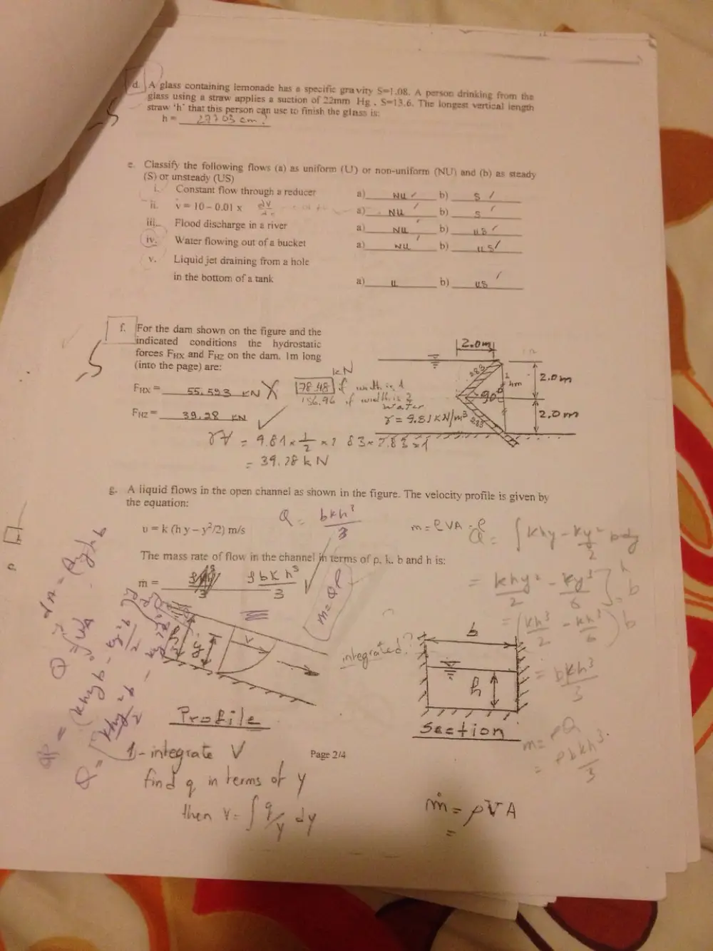
d. \ Av glass containing lemonade has a specific gravity S=!
A person drinking from the
3.6. The longest vertical length
glass using a straw applies a su
straw ‘h” that
2mm Hg.
S person can use to finish the gias
Classify the following flows (a) as uniform (U) or
(S) or unsteady (US)
Constant flow through a reducer
non-uniform
Flood discharge in a river
Water flowing out of a buck
Liquid jet draining fro
in the bottom of a tank
For the dam shown on the figure and the
indicated conditions
hydrostatic
forces Fy and Fy on the dam. Im long
(NU) and (b) as steady
b) 4
b) "Se:
Do). af
cP,
‘ /
pp penteensl | ales
(into the page) are:
A liquid flows in the open channe
as shown in the figure. The velocity profile is given by
the equation:
k(hy-y
rr
“ROTI ANT ABCUITECTUR
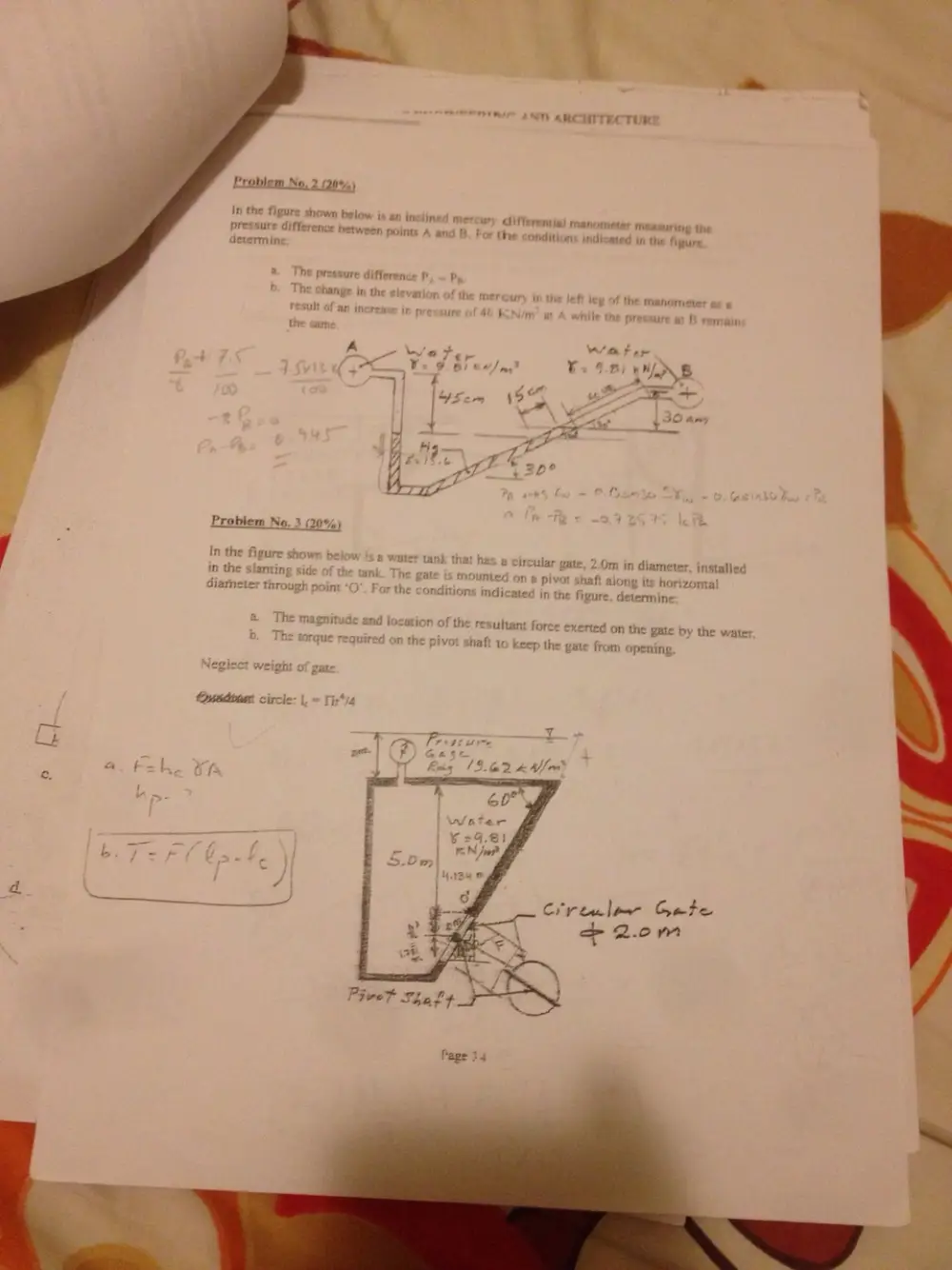
Problem No, 2 (20%)
In the figure shown below i an inclined mercury differemial anoMeler measuring the
pressure d ee between points A and B. Fo the conditions indicated in the figure
jevermine
The pressure difference P, — }
The change in the elevatior ury in th ft | the manor
it of an increase j ir 40 & n # hile the pressure at B remair
the sam
; - _ 30 am
t ge ,
|
q-
E% 3D?
Problem No. 3
r In the figure showr w is @ water tank that has # circul: 2Drn ict Giaenetee bias
in the Sianting th The . ‘
ank unted or along its horizonta
diarne!
throug} mt *O". For the condition indicated in the figure, determine
and location of the resultant force exerted on the gate by the water
b. The torque required on the pivot haft to keep the gate from opening
rt
ct :
a. k=l “a
c.
Crrinlme Gete
- 2.0m
Problem No. 4 (20%,