
CIVE 410 Homework 5 with Solution, Spring 2011
American University of Beirut · Structures II · 9 pages · with solution
More CIVE 410 files
- Homework 3 · Spring 2013HomeworkView
- Homework 7 · Spring 2013HomeworkView
- Homework 6 · Spring 2013HomeworkView
- Homework 2 · Spring 2013HomeworkView
- Homework 4 with Solution · Spring 2011Homework · with solutionView
- Homework · Spring 2008HomeworkView
- Homework · Spring 2008HomeworkView
- Homework · Spring 2008HomeworkView
Show the text of this homework
American University of Beirut
Civil Engineering Dept. Faculty of Eng. & Arch.
Structures ll — CIVE410 - Homework [5] Spring 2011
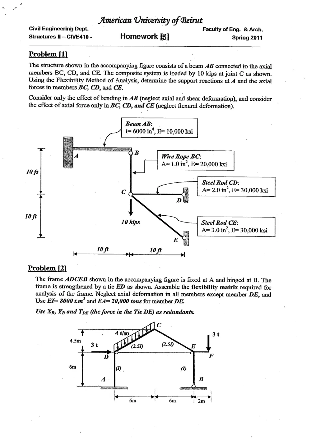
Problem [1]
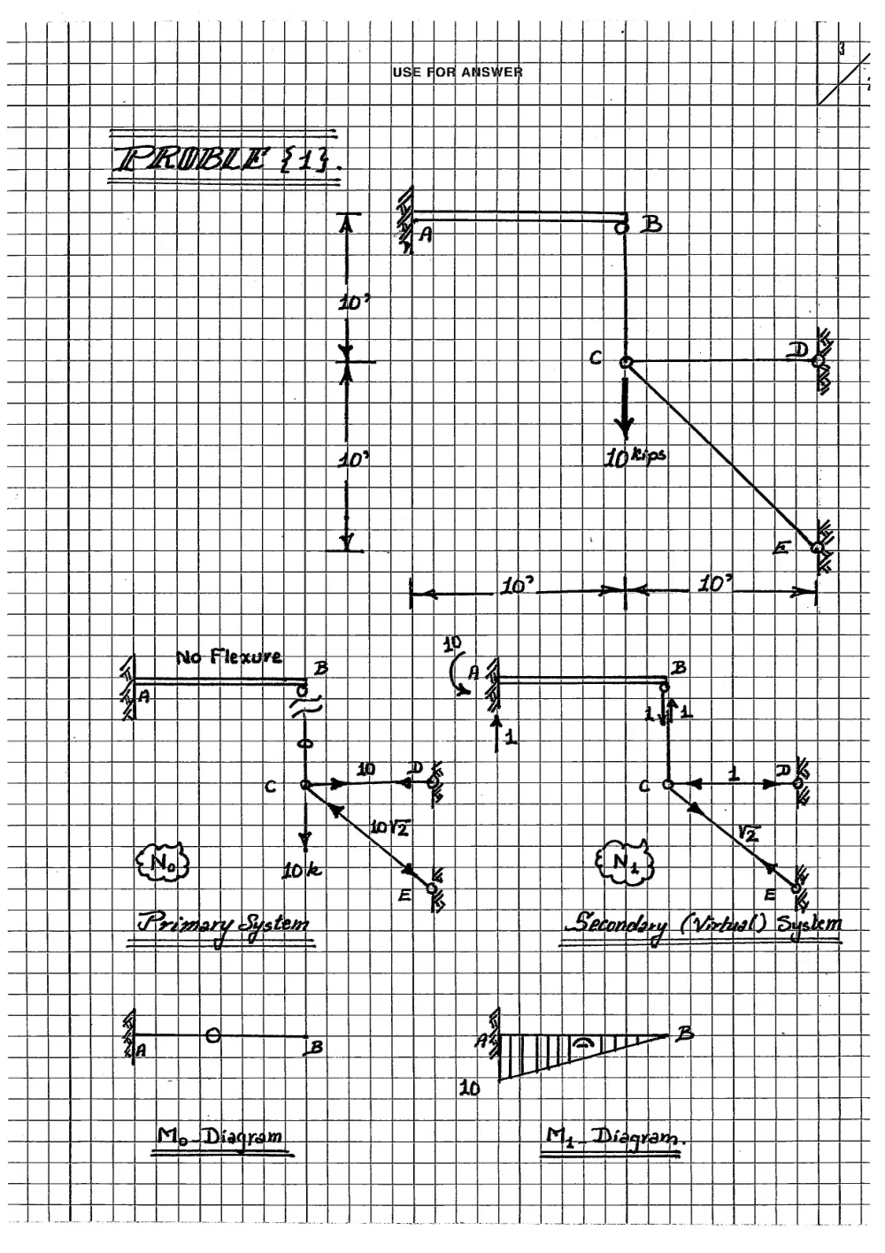
The structure shown in the accompanying figure consists of a beam AB connected to the axial
members BC, CD, and CE. The composite system is loaded by 10 kips at joint C as shown.
Using the Flexibility Method of Analysis, determine the support reactions at A and the axial
forces in members BC, CD, and CE.
Consider only the effect of bending in AB (neglect axial and shear deformation), and consider
the effect of axial force only in BC, CD, and CE (neglect flexural deformation).
Beam AB: -
= 6000 in*, E= 10,000 ksi
EES eno cam |
B
Wire RopeBC:
A= 1.0 in’, E= 20,000 ksi
10 ft
Steel Rod CD: |
A= 2.0 in’, E= 30,000 ksi
10
ft Steel Rod CE:
A= 3.0 in’, E= 30,000 ksi
10
\< ft
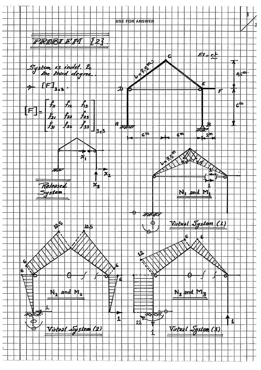
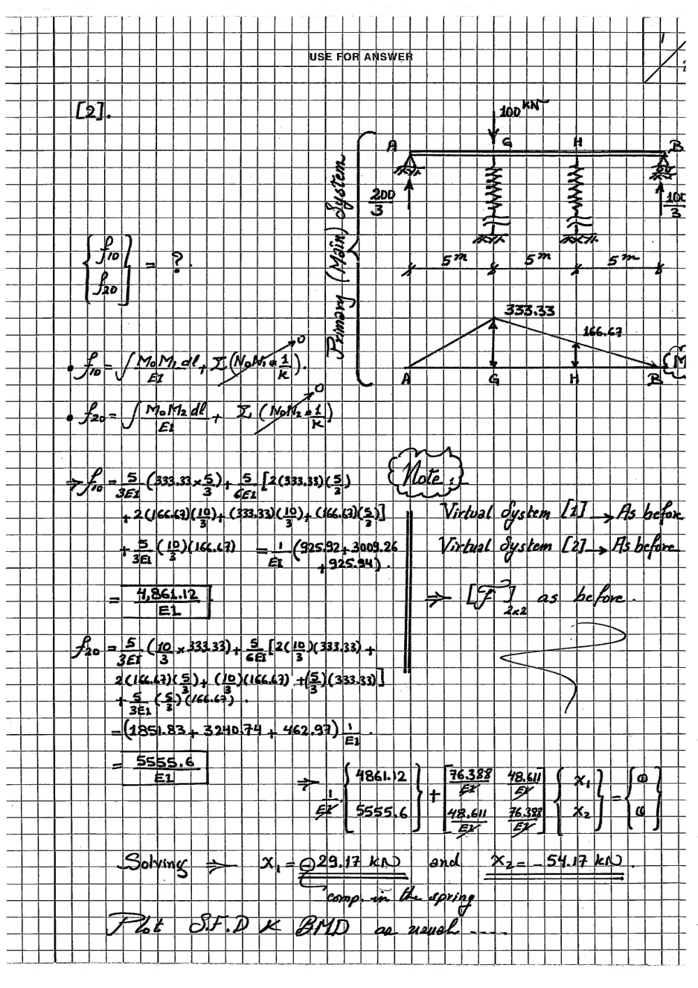
Problem [2]
The frame ADCEB shown in the accompanying figure is fixed at A and hinged at B. The
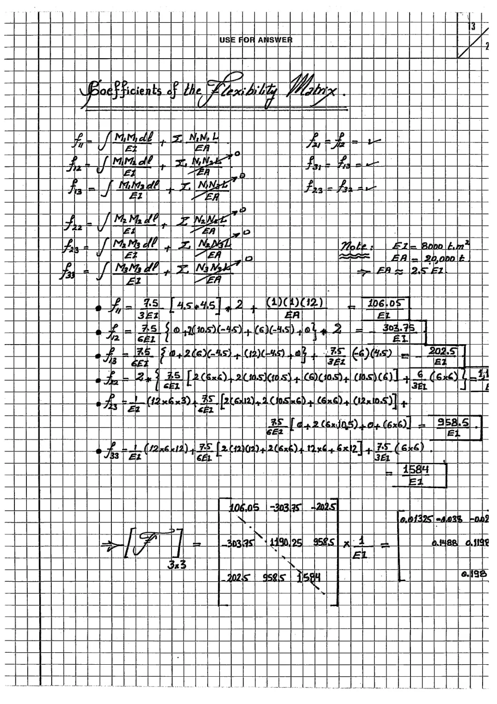
frame is strengthened by a tie ED as shown. Assemble the flexibility matrix required for
analysis of the frame. Neglect axial deformation in all members except member DE, and
Use EI= 8000 t.m’ and EA= 20,000 tons for member DE.
Use Xp, Vz and Tor (the force in the Tie DE) as redundants.
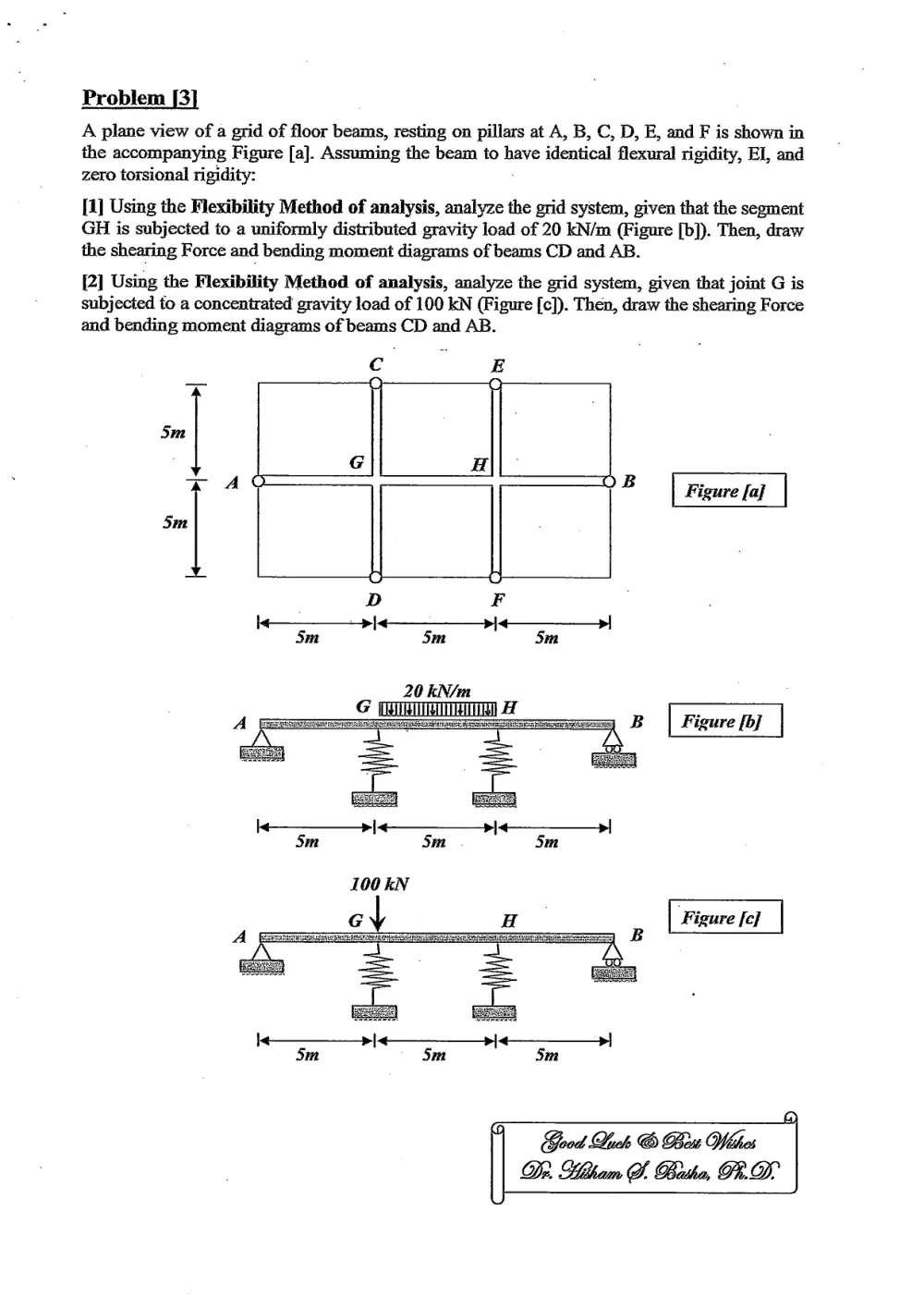
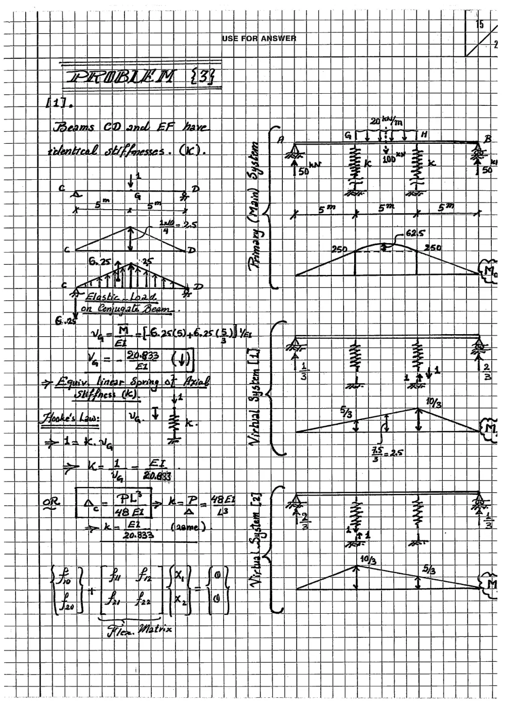
Problem [3]
A plane view of a grid of floor beams, resting on pillars at A, B, C, D, E, and F is shown in
the accompanying Figure [a]. Assuming the beam to have identical flexural rigidity, El, and
zero torsional rigidity:
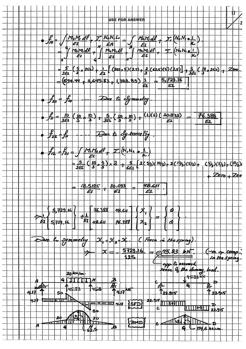
[1] Using the Flexibility Method of analysis, analyze the grid system, given that the segment
GH is subjected to a uniformly distributed gravity load of 20 KN/m (Figure [b]). Then, draw
the shearing Force and bending moment diagrams of beams CD and AB.
[2] Using the Flexibility Method of analysis, analyze the grid system, given that joint G is
subjected to a concentrated gravity load of 100 KN (Figure [c]). Then, draw the shearing Force
and bending moment diagrams of beams CD and AB.
OB | Figure fa]
Sm
c
Sm
G vig
D
Qh ————— Oy
20 kN/m
¢ i) 2 ;
A === maema ass ——z—;z 2. B Figure ii
Good Luck Bou Wthes
——
aay
us
E FOR ANSWER
PS
= B 7
:
C
|
Rips
Z
x
flexure, z
| |
re ea
Lom q
#0; K
E|
Z
a — + = == =
le~ _
FI
| ;
| lus OR} ANS ER he
| Zz
| | |
| Yas =
_| HAL | | | WoWaLy | (40) (-) (46 » ~1o¥21) (V2 )Cipva)
vo Al Bp, boa se 2.) 30,000 |
bi ;
L | lolog 4 2% iol |
i > 19512 a drtatay
| ac anss +3, | ET abode
(4) C4) (40 12) 2) (Nz) Clove #12
| | +f ee +B, we x /S.b |
_| 404 (10 ¥10) | 12 g
ial + 3 iba oh ee aad ‘ |
= po3& 4,0 ener an B¥ tal,
a Ae TRUST pk |
th a/ | 1p. b23F emia
ay : ase.
Pee ; psel_of ae. mica hohe TEDSs
| rad tel, |
st a L La) | = g
SOEEECUSCTEGLEcuacece®<2"cthasteeeed!
| = : Lt oF | IC leseian)|.
| =| ol 4! A = boll as .
Ma l= be 2.70) (4.40) | 27 44>
|
|
| |
HE ee Lt
lus FOR ANSWE
ni
CHEE
USE FOR ANSWER
tt
ae \ ain
= Le
|_| x iS a: ts |_|
E :
ata ri
SF a ie L] ~
a =e a im
2
z fs ry eayeeaicy- ‘2 is penqary [zy An]
4 ce :
: Le | a ql 3
Waal . x t
| sh d q Earn : 14 j ant
| vari lg te et alg Ae
i 3 : er st alg st tS
8... ‘ f
a a
USE FOR ANSWE
2" i ‘
" | ann as
: HH os SRO cer meee
|_| | tit |
5 2 | 7S a |
a: oy 2 Ml !
;__| . i” H
; oe iN
Ha g | : rc
: ooRg part
opera on ger Data
ly aE 1 Geel +4 a oe = :
Rae 2 -acaereereceat (itn ae
: i z Ste ld y_ | i |
ane mR ol S L_ Mi t i |
r-’ 9 E
j sts ail |
Ment et eCae? CeCee carer |
|_| | so . w et) | : |
| == SS alg ig = ala rn a phe :
: of SA] A : s tt — ‘ !
gis: eeterontiet tae tae
: | BERR
|