
CIVE 411 Final Two Previouses, Fall 2016
American University of Beirut · Indeterminate Structures · 39 pages


Showing the first 10 of 39 pages. Download the PDF to see all of it.
More CIVE 411 files
Show the text of this final exam
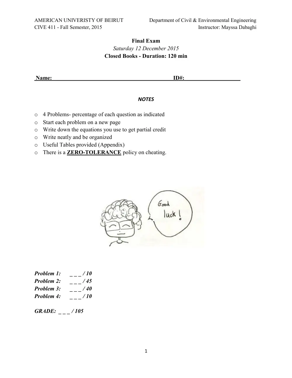
AMERICAN UNIVERISTY OF BEIRUT
Department of Civil & Environmental Engineering
CIVE 411 - Fall Semester, 2015
Instructor: Mayssa Dabaghi
1
Final Exam
Saturday 12 December 2015
Closed Books - Duration: 120 min
Name:
ID#:
NOTES
o 4 Problems- percentage of each question as indicated
o Start each problem on a new page
o Write down the equations you use to get partial credit
o Write neatly and be organized
o Useful Tables provided (Appendix)
o There is a ZERO-TOLERANCE policy on cheating.
Problem 1:
_ _ _ / 10
Problem 2:
_ _ _ / 45
Problem 3:
_ _ _ / 40
Problem 4:
_ _ _ / 10
GRADE: _ _ _ / 105
AMERICAN UNIVERISTY OF BEIRUT
Department of Civil & Environmental Engineering
CIVE 411 - Fall Semester, 2015
Instructor: Mayssa Dabaghi
2
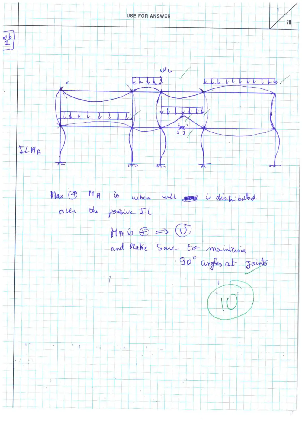
Problem 1: (10 points)
The frame shown in Figure 1 is fixed at its base.
Using qualitative influence lines, determine the arrangement of a uniformly distributed live load
�� to cause the maximum positive bending moment at A.
Figure 1
AMERICAN UNIVERISTY OF BEIRUT
Department of Civil & Environmental Engineering
CIVE 411 - Fall Semester, 2015
Instructor: Mayssa Dabaghi
3
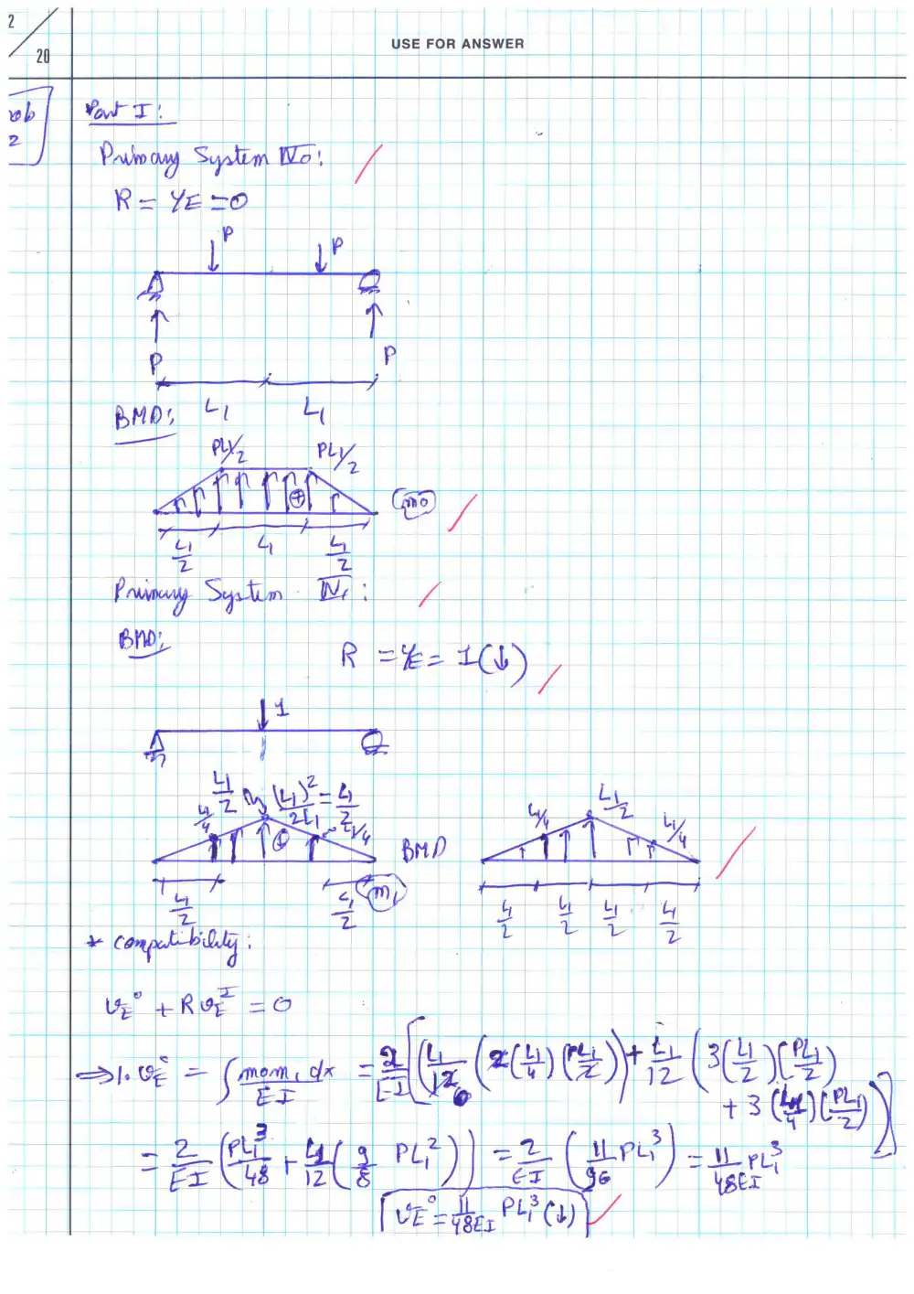
Problem 2: (45 points)
The plan view of a grid of floor beams, resting on pillars at A, B, C, and D is shown in Figure
2.a. The loading consists of 2 concentrated forces � (gravity loads) at mid-span of AE and EB, as
shown. Beam AB has flexural rigidity �� and zero torsional rigidity.
Provide your answers to the following questions in terms of �, ��, ��, and ��, whichever
applicable. Axial and shear deformations are neglected.
Figure 2.a
Part I:
First, it is assumed that beam CD is infinitely stiff, such that beam AB can be idealized as
follows:
Figure 2.b
[A]
Using the Force Method of analysis, and using �� as redundant, draw
the shear and bending moment diagrams of beam AB.
(20 points) □
[B]
Using the principle of virtual work, and making use of symmetry,
compute the deflection Δ at mid-span of AE and EB (i.e., at the location
of the applied forces).
(10 points) □
AMERICAN UNIVERISTY OF BEIRUT
Department of Civil & Environmental Engineering
CIVE 411 - Fall Semester, 2015
Instructor: Mayssa Dabaghi
4
Part II:
Now, it is assumed that beam CD also has stiffness ��, such that beam CD can be idealized as an
axial spring, and beam AB can be idealized as follows:
Figure 2.c
[C]
If CD is simply supported at C and D, what is the value of ��?
(5 points) □
[D]
Compute ��. Compare with �� in part [A] and comment.
(10 points) □
AMERICAN UNIVERISTY OF BEIRUT
Department of Civil & Environmental Engineering
CIVE 411 - Fall Semester, 2015
Instructor: Mayssa Dabaghi
5
Problem 3: (40 points)
Frame ABC is loaded as shown in Figure 3. The frame is fixed at A and supported by a roller at
C.
Notice: The flexural rigidity is (EI) for the beam and (2EI) for the column. The lengths are also
different!
Using the slope-deflection method,
[A]
Compute �� (horizontal displacement at B) and �� (rotation at B).
(20 points) □
[B]
Draw the shear and moment diagrams of the frame.
(15 points) □
[C]
Use your results in [A] and [B] to sketch the deflected shape.
(5 points) □
Neglect the effect of axial and shear deformations.
You can use � = � � and �� = ��, ��� ��. ��.
Figure 3
AMERICAN UNIVERISTY OF BEIRUT
Department of Civil & Environmental Engineering
CIVE 411 - Fall Semester, 2015
Instructor: Mayssa Dabaghi
6
Problem 4: (10 points)
Beam AB shown in Figure 4 is a propped cantilever; it is fixed at A and supported by a hinge at
B. �� is constant.
The slope-deflection equation for a propped cantilever span AB is given by:
��� = 3��
���
�� − 3��
���
��� + �����
�
Prove the first term of this equation, i.e., that the fixed-end moment at A due to node rotation ��
is given by ��� =
���
��� ��.
Figure 4
AMERICAN UNIVERISTY OF BEIRUT
Department of Civil & Environmental Engineering
CIVE 411 - Fall Semester, 2015
Instructor: Mayssa Dabaghi
7
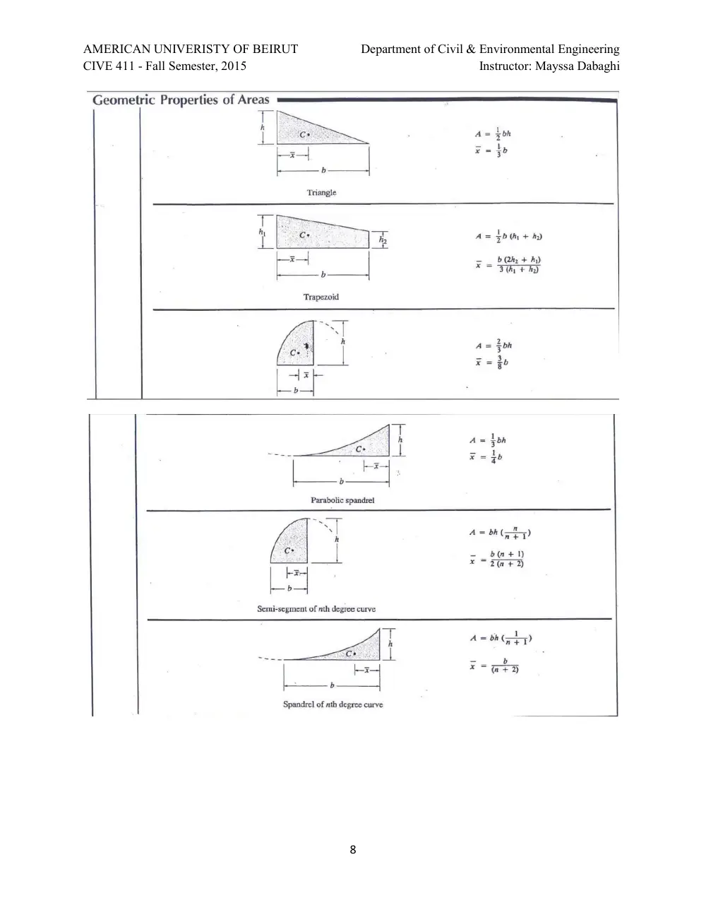
APPENDIX – Useful Tables
AMERICAN UNIVERISTY OF BEIRUT
Department of Civil & Environmental Engineering
CIVE 411 - Fall Semester, 2015
Instructor: Mayssa Dabaghi
8
AMERICAN UNIVERISTY OF BEIRUT
Department of Civil & Environmental Engineering
CIVE 410A - Spring Semester, 2015
Instructor: Mayssa Dabaghi
1
Final Exam
Saturday, 9 May 2015
Closed Books - Duration: 120 min
Name:
ID#:
NOTES
o 5 Problems- percentage of each question as indicated
o Useful Tables provided (Appendix)
o Provide all answers on these question sheets
o Write neatly and be organized
o There is a ZERO-TOLERANCE policy on cheating.
COMMENTS
---------------------------------------------------------------------------------------------------------------------
---------------------------------------------------------------------------------------------------------------------
---------------------------------------------------------------------------------------------------------------------
Problem 1:
_ _ _ / 10
Problem 2:
_ _ _ / 15
Problem 3:
_ _ _ / 35
Problem 4:
_ _ _ / 15
Problem 5:
_ _ _ / 30
GRADE: _ _ _ / 105
AMERICAN UNIVERISTY OF BEIRUT
Department of Civil & Environmental Engineering
CIVE 410A - Spring Semester, 2015
Instructor: Mayssa Dabaghi
2
Problem 1: (10 points)
The frame shown in Figure 1 is fixed at its base.
On which beams (or portions thereof) should distributed loading be placed to maximize the
positive moment at A.
Figure 1
AMERICAN UNIVERISTY OF BEIRUT
Department of Civil & Environmental Engineering
CIVE 410A - Spring Semester, 2015
Instructor: Mayssa Dabaghi
3
Problem 2: (15 points)
Assemble the flexibility matrix of the truss structure shown in Figure 2.
�� is constant.
Use �� and �� as redundants. Do NOT solve for the redundants.
Figure 2
AMERICAN UNIVERISTY OF BEIRUT
Department of Civil & Environmental Engineering
CIVE 410A - Spring Semester, 2015
Instructor: Mayssa Dabaghi
4
Problem 3: (35 points)
Frame ABCD is loaded as shown in Figure 3. The frame is fixed at B and C, and supported by a
roller at A.
Notice: The flexural rigidity is (EI) for the beam and (2EI) for the columns. The lengths are also
different!
Using the slope-deflection method,
[A]
Compute �� (horizontal displacement at A) and �� (rotation at D)
(15 points) □
[B]
Draw the moment diagram of beam AD
(10 points) □
[C]
(*) Use the principal of virtual work to compute the vertical displacement
at the mid-span of AD. (Hint: carefully select your virtual structure)
(10 points) □
Neglect the effect of axial and shear deformations.
You can use � = � � and �� = ��, ��� ��. ��.
Figure 3
AMERICAN UNIVERISTY OF BEIRUT
Department of Civil & Environmental Engineering
CIVE 410A - Spring Semester, 2015
Instructor: Mayssa Dabaghi
5
Problem 4: (15 points)
Beam ABC shown in Figure 4 is fixed at A and C. Assemble its classical stiffness matrix.
�� is constant.
Do NOT solve for the unknown DOFs. Neglect the effect of axial and shear deformations.
Figure 4
AMERICAN UNIVERISTY OF BEIRUT
Department of Civil & Environmental Engineering
CIVE 410A - Spring Semester, 2015
Instructor: Mayssa Dabaghi
6
Problem 5: (30 points)
Frame ABCD is loaded as shown in Figure 5. It is fixed at A, B, and C. �� is constant.
[A]
Select a method of analysis for this structure. Justify your choice.
(2 points) □
[B]
Draw the shear and moment diagrams of the frame. Comment on how
the applied moment is distributed.
(13 points) □
[C]
Sketch the deflected shape.
(5 points) □
Now in addition to the concentrated moment, the support at B settles by Δ� = 1 cm downwards.
[D]
Draw the moment diagram and sketch the deflected shape.
(10 points) □
Neglect the effect of axial and shear deformations.
You can use � = ��� ��. �, � = � �, and �� = ��, ��� ��. ��.
Figure 5
AMERICAN UNIVERISTY OF BEIRUT
Department of Civil & Environmental Engineering
CIVE 410A - Spring Semester, 2015
Instructor: Mayssa Dabaghi
7
APPENDIX – Useful Tables
AMERICAN UNIVERISTY OF BEIRUT
Department of Civil & Environmental Engineering
CIVE 410A - Spring Semester, 2015
Instructor: Mayssa Dabaghi
8