
CIVE 421 Other, Spring 2008
American University of Beirut · Concrete II · 2 pages
More CIVE 421 files
Show the text of this file
FACULTY OF ENGINEERING & ARCHITECTURE
AMERICAN UNIVERSITY OF BEIRUT
CE-421_ CONCRETE I
1 (2 HOURS), A 10, 2007
{OPEN BOOK)
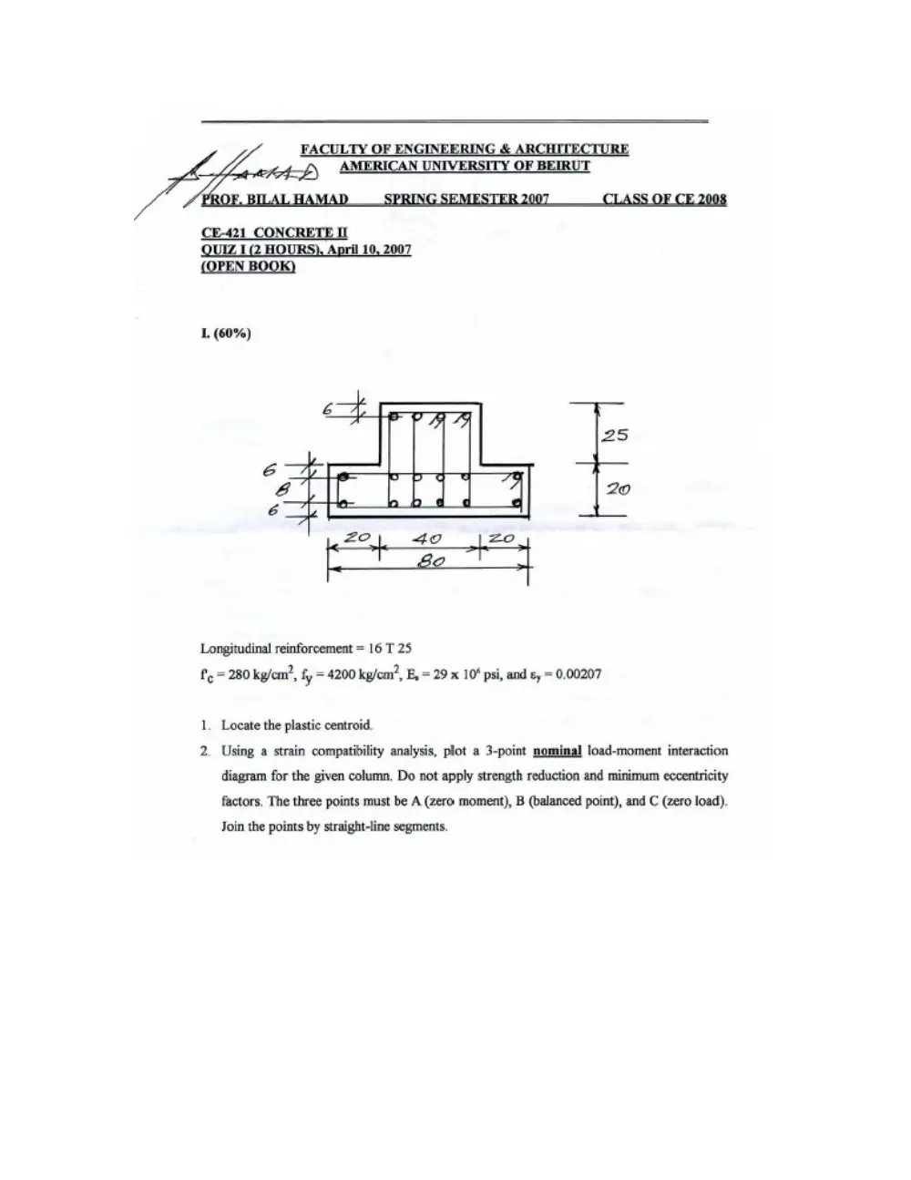
1. (60%)
&
25
e
4 20
é
| =2.4 40 -=? |
Longitudinal reinforcement = 16 T 25
Pf, = 280 kg/em’, fy = 4200 kp/em®, E,= 29 x 10* psi, and ¢y = 0.00207
1. Locate the plastic centroid.
2. Using a strain compatibility analysis, plot a 3-point nominal load-moment interaction
diagram for the given column. Do not apply strength reduction and minimum eccentricity
factors. The three points must be A (zero moment), B (balanced point), and C (zero load).
Join the points by straight-line segments.
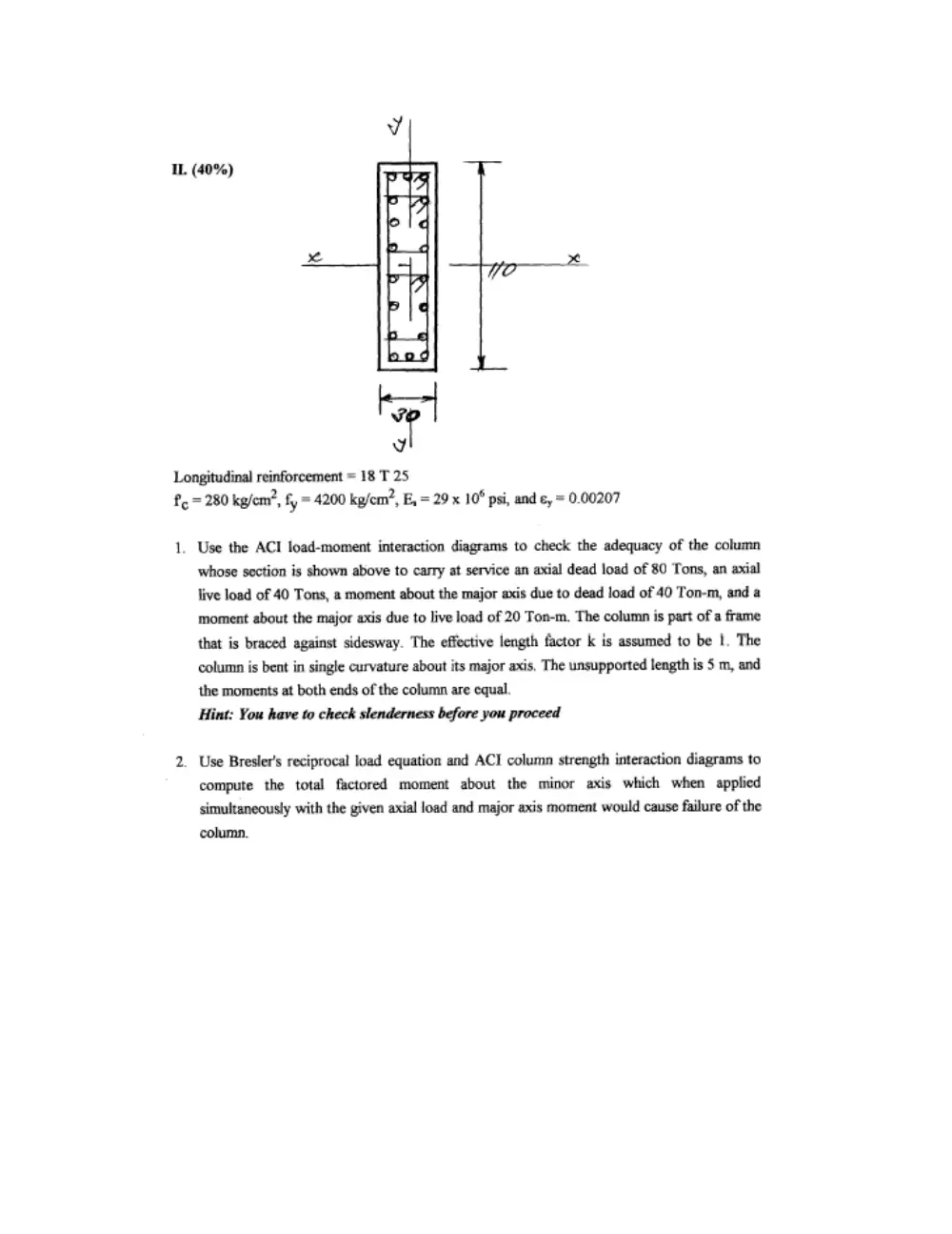
IL. (40%) “fk
jt
F
v7
Longitudinal reinforcement = 18 T 25
f= 280 kg/em’, f, = 4200 kg/cm’, E, = 29 x 10° psi, and e, = 0.00207
1.
Use the ACI load-moment interaction diagrams to check the adequacy of the column
whose section is shown above to carry at service an axial dead load of 80 Tons, an axial
live load of 40 Tons, a moment about the major axis due to dead load of 40 Ton-m, and a
moment about the major axis due to live load of 20 Ton-m. The column is part of a frame
that is braced against sidesway. The effective length factor k is assumed to be |. The
column is bent in single curvature about its major axis, The unsupported length is 5 m, and
the moments at both ends of the column are equal.
Hint: You have to check slenderness before you proceed
Use Bresler's reciprocal load equation and ACT column strength interaction diagrams to
compute the total factored moment about the minor axis which when applied
simultaneously with the given axial load and major axis moment would cause failure of the
column.