
CIVE 440 Notes Instructor Notes, Fall 2012
American University of Beirut · Hydraulics and Laboratory · 118 pages






Showing the first 10 of 118 pages. Download the PDF to see all of it.
Show the text of this notes
Hydraulics & Laboratory
September 2012
Printing History: Sep. 2005; Oct. 2006; Oct. 2009; Feb. 2010; Nov. 2011; Sep. 2012
Hydraulics & Laboratory
Syllabus
Syllabus
Semester:
Fall 2012
Course No:
CIVE 440
Course Title:
Hydraulics & Laboratory
Prerequisites:
CIVE 340 Fluid Mechanics
Class Schedule:
Tu. & Th. 12:30–13:50; Tu. & Th. 14:00–15:20 or On-Call-Basis
Classroom:
Bechtel Rm. 545
Instructor:
Habib Basha
Office:
Bechtel Rm. 535
Hours:
Tu. & Th.: 11:30–12:30 & 15:30–16:30 or by appointment
Topics
Flow in Conduits; Flow in Open-Channels; Flow Measurements; Laboratory Experiments.
Textbook
Crowe, C. T., Elger, D. F., and Roberson, J. A., Engineering Fluid Mechanics, 9th ed.,
chap. 10, 13, & 15, John Wiley & Sons, New York, 2010.
Course Description
Hydraulics deals with the application of fluid mechanics in the analysis and design of
hydraulic structures and water resources systems. The course is important in that it
provides the technical background in the design of water resources projects. The primary
applications are in the analysis of flow in water distribution systems and the design of
canals and related structures for irrigation projects. Another important application is in
measurements of discharge in conduits and in channels. The course is divided in two
main parts covering pipe flow and open-channel flow. Laboratory experiments dealing
with flow measurements and pipe friction are also conducted.
Course Learning Outcomes
Students will know the fundamental hydraulic concepts.
Students will have the ability to solve pipe-flow problems.
Students will have the ability to compute water-surface profiles in open-channels.
Students will have the ability to design basic hydraulic structures.
Students will have the ability to measure discharge in water systems.
Students will have had a hands-on experience of hydraulics in the laboratory.
Students will be skilled in the use of major technical software.
Students will have basic technical writing skills.
Hydraulics & Laboratory
Syllabus
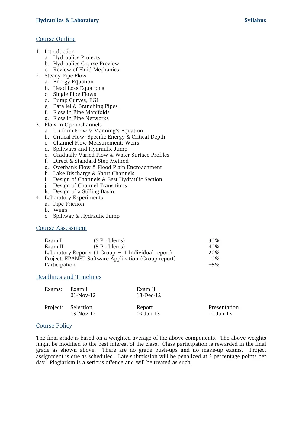
Course Outline
1. Introduction
a. Hydraulics Projects
b. Hydraulics Course Preview
c. Review of Fluid Mechanics
2. Steady Pipe Flow
a. Energy Equation
b. Head Loss Equations
c. Single Pipe Flows
d. Pump Curves, EGL
e. Parallel & Branching Pipes
f. Flow in Pipe Manifolds
g. Flow in Pipe Networks
3. Flow in Open-Channels
a. Uniform Flow & Manning’s Equation
b. Critical Flow: Specific Energy & Critical Depth
c. Channel Flow Measurement: Weirs
d. Spillways and Hydraulic Jump
e. Gradually Varied Flow & Water Surface Profiles
f. Direct & Standard Step Method
g. Overbank Flow & Flood Plain Encroachment
h. Lake Discharge & Short Channels
i. Design of Channels & Best Hydraulic Section
j. Design of Channel Transitions
k. Design of a Stilling Basin
4. Laboratory Experiments
a. Pipe Friction
b. Weirs
c. Spillway & Hydraulic Jump
Course Assessment
Exam I
(5 Problems)
30%
Exam II
(5 Problems)
40%
Laboratory Reports (1 Group + 1 Individual report)
20%
Project: EPANET Software Application (Group report)
10%
Participation
5%
Deadlines and Timelines
Exams:
Exam I
Exam II
01-Nov-12
13-Dec-12
Project: Selection
Report
Presentation
13-Nov-12
09-Jan-13
10-Jan-13
Course Policy
The final grade is based on a weighted average of the above components. The above weights
might be modified to the best interest of the class. Class participation is rewarded in the final
grade as shown above. There are no grade push-ups and no make-up exams. Project
assignment is due as scheduled. Late submission will be penalized at 5 percentage points per
day. Plagiarism is a serious offence and will be treated as such.
Hydraulics & Laboratory
Syllabus
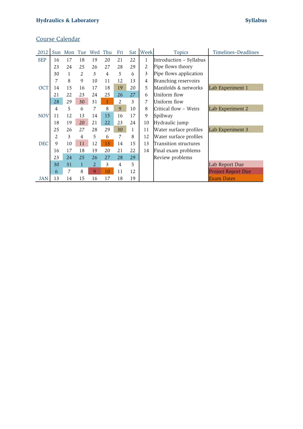
Course Calendar
2012 Sun Mon Tue Wed Thu Fri
Sat Week
Topics
Timelines–Deadlines
SEP
16
17
18
19
20
21
22
1
Introduction – Syllabus
23
24
25
26
27
28
29
2
Pipe flows theory
30
1
2
3
4
5
6
3
Pipe flows application
7
8
9
10
11
12
13
4
Branching reservoirs
OCT 14
15
16
17
18
19
20
5
Manifolds & networks
Lab Experiment 1
21
22
23
24
25
26
27
6
Uniform flow
28
29
30
31
1
2
3
7
Uniform flow
4
5
6
7
8
9
10
8
Critical flow – Weirs
Lab Experiment 2
NOV 11
12
13
14
15
16
17
9
Spillway
18
19
20
21
22
23
24
10 Hydraulic jump
25
26
27
28
29
30
1
11 Water surface profiles
Lab Experiment 3
2
3
4
5
6
7
8
12 Water surface profiles
DEC
9
10
11
12
13
14
15
13 Transition structures
16
17
18
19
20
21
22
14 Final exam problems
23
24
25
26
27
28
29
Review problems
30
31
1
2
3
4
5
Lab Report Due
6
7
8
9
10
11
12
Project Report Due
JAN 13
14
15
16
17
18
19
Exam Dates
Hydraulics & Laboratory
Table of Contents
Table of Contents
Hydraulics & Laboratory ..................................................................................................... i
Syllabus ............................................................................................................................ iii
Table of Contents ............................................................................................................. vii
1. Introduction .................................................................................................................. 1
1.1 Water Networks ....................................................................................................... 1
1.2 Irrigation System ...................................................................................................... 2
2. Steady Pipe Flows ......................................................................................................... 3
2.1 Continuity Equation ................................................................................................. 3
2.2 Energy Equation ....................................................................................................... 3
2.3 Laminar and Turbulent Flow .................................................................................... 4
2.4 Head Loss Equations ................................................................................................ 4
2.4.1
Pipe Friction Losses ........................................................................................ 4
2.4.2
Pipe Fitting Losses .......................................................................................... 5
2.5 Power, EGL and HGL ............................................................................................... 5
2.6 Solution of Pipe-Flow Problems ................................................................................ 5
2.7 Conduit Systems .................................................................................................... 11
3. Flow in Open-Channels ................................................................................................ 21
3.1 Uniform Flow ......................................................................................................... 21
3.1.1
Manning’s Equation ...................................................................................... 21
3.1.2
Compound Channel ...................................................................................... 22
3.1.3
Best Hydraulic Section................................................................................... 22
3.1.4
Flood Plain Encroachment ............................................................................. 22
3.1.5
Design of Erodible Channels .......................................................................... 22
3.2 Critical Flow .......................................................................................................... 22
3.3 Energy Equation ..................................................................................................... 23
3.4 Weirs..................................................................................................................... 24
3.4.1
Broad-crested weirs ....................................................................................... 24
3.4.2
Sharp-crested weirs ....................................................................................... 24
3.5 Hydraulic Jump ...................................................................................................... 25
3.6 Gradually Varied Flow ............................................................................................ 25
3.6.1
Direct Step Method ....................................................................................... 26
3.6.2
Standard Step Method ................................................................................... 26
3.7 Flood Plain Delineation .......................................................................................... 26
3.8 Design of Channel Transitions ................................................................................ 27
Appendix ......................................................................................................................... 39
Homework Problems 2006 .............................................................................................. 107
Homework Problems 2008 .............................................................................................. 118
Homework Problems 2009 .............................................................................................. 129
Homework Problems 2010S ............................................................................................. 140
Homework Problems 2010F ............................................................................................. 146
Homework Problems 2011 .............................................................................................. 152
Homework Problems 2011F ............................................................................................. 158
Experiments ................................................................................................................... 165
Formulae Sheet I ................................................................................................................ 1
Formulae Sheet II ............................................................................................................... 2
1
1. Introduction
Hydraulic engineering deals with the analysis and design of hydraulic structures and water
resources systems. The primary applications are in the analysis of flow in water distribution
systems and the design of canals and related structures for irrigation projects. Another
important application is in measurements of discharge in conduits and in channels.
1.1 Water Networks
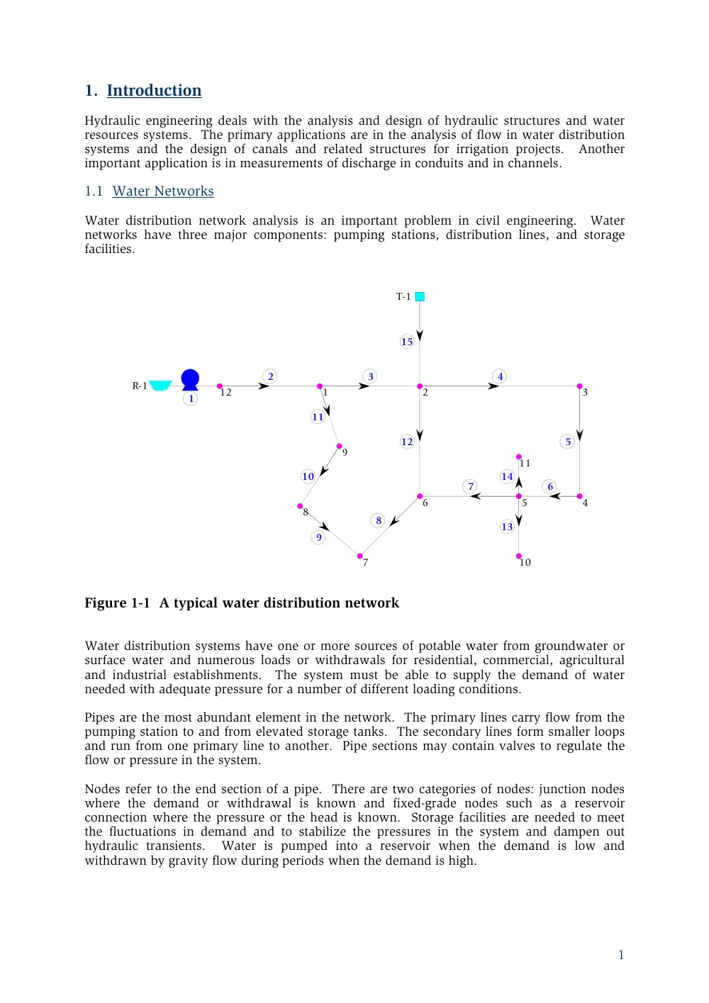
Water distribution network analysis is an important problem in civil engineering. Water
networks have three major components: pumping stations, distribution lines, and storage
facilities.
1
2
3
4
5
6
7
8
9
10
11
12
13
14
15
1
2
3
4
5
6
7
8
9
10
11
12
R-1
T-1
Figure 1-1 A typical water distribution network
Water distribution systems have one or more sources of potable water from groundwater or
surface water and numerous loads or withdrawals for residential, commercial, agricultural
and industrial establishments. The system must be able to supply the demand of water
needed with adequate pressure for a number of different loading conditions.
Pipes are the most abundant element in the network. The primary lines carry flow from the
pumping station to and from elevated storage tanks. The secondary lines form smaller loops
and run from one primary line to another. Pipe sections may contain valves to regulate the
flow or pressure in the system.
Nodes refer to the end section of a pipe. There are two categories of nodes: junction nodes
where the demand or withdrawal is known and fixed-grade nodes such as a reservoir
connection where the pressure or the head is known. Storage facilities are needed to meet
the fluctuations in demand and to stabilize the pressures in the system and dampen out
hydraulic transients. Water is pumped into a reservoir when the demand is low and
withdrawn by gravity flow during periods when the demand is high.
Introduction
2
1.2 Irrigation System
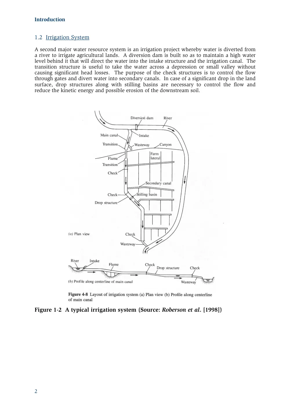
A second major water resource system is an irrigation project whereby water is diverted from
a river to irrigate agricultural lands. A diversion dam is built so as to maintain a high water
level behind it that will direct the water into the intake structure and the irrigation canal. The
transition structure is useful to take the water across a depression or small valley without
causing significant head losses. The purpose of the check structures is to control the flow
through gates and divert water into secondary canals. In case of a significant drop in the land
surface, drop structures along with stilling basins are necessary to control the flow and
reduce the kinetic energy and possible erosion of the downstream soil.
Figure 1-2 A typical irrigation system (Source: Roberson et al. [1998])
3
2. Steady Pipe Flows
Flow in conduits arises in many fields of engineering. Water distribution systems are one
prime application of the theory of conduit flows. The basic principles governing closed
conduit flows are: conservation of mass, conservation of energy, and conservation of
momentum. The continuity and energy equations are used to design a pipe system, while
the momentum equation is employed to determine the forces acting on bends for a given
discharge.
2.1 Continuity Equation
The continuity equation is expressed by
dS
Q
Q
dt
in
out
(2.1)
where
in
Q and
Qout
are the flow rates entering and exiting the system, and S is the volume of
water stored in the system. For steady flow, eq. (2.1) simplifies to
in
out
Q
Q
or
A V
A
V
in
in
out
out
(2.2)
where A is the cross-sectional area of the flow.
2.2 Energy Equation
The energy equation is given by
p
t
L
p
V
p
V
z
h
z
h
h
g
g
2
2
1
1
2
2
1
1
2
2
2
2
(2.3)
where p is the pressure head (i.e. the energy possessed by the liquid in virtue of its
pressure),
V2 2
g is the velocity head (i.e. the kinetic energy per unit weight of a flowing
liquid), z is the elevation head (potential energy),
p
h is the head supplied by the pump,
th
is the head supplied by the turbine, and
L
h is the head loss between section 1 and 2.
The correction factor in the velocity head term accounts for the assumption of a mean
velocity in (2.3) whereas the actual velocity distribution is varying from a maximum at the
centerline to zero at the boundaries
u dA
AV
3
3
1
(2.4)
Here u is the actual velocity distribution and V is the mean velocity. The parameter ranges
from 1.01 to 1.15 and is usually assumed to be unity in pipe flow computations.
The sum of the pressure head, the velocity head, and the elevation head is defined as the
hydraulic head H
p
V
H
z
g
2
2
(2.5)
Water flows from a higher head H to a lower head. Eq. (2.3) can then be expressed as
1
2
p
t
L
H
h
H
h
h
. It applies to incompressible steady flow of a real viscous fluid
flowing from an inlet section to an outlet section. If
L
h 0 , the fluid is assumed to be
inviscid, i.e. frictionless. For
p
t
L
h
h
h
0 , eq. (2.3) reduces to the Bernoulli equation.
Steady Pipe Flows
4
2.3 Laminar and Turbulent Flow
Flow of water is mostly turbulent; the flow of oil can be laminar. The flow is considered
laminar when the Reynolds number is less than 2000, and it is turbulent for Reynolds number
greater than 3000. The velocity profile in laminar flows is parabolic while the velocity
distribution in turbulent flows is of the form of a power law formula.
2.4 Head Loss Equations
2.4.1 Pipe Friction Losses
In laminar flows, the head loss is proportional to V. The mathematical equations become
easier to solve since they are linear. On the other hand, the head loss in turbulent flows is
proportional to
n
V . The governing equations are therefore nonlinear and more difficult to
solve. Dimensional analysis and experimental investigations are used to come up with the
head loss equation.
For laminar flow in pipes, the friction equation can be derived from the shear stress
distribution and the parabolic velocity distribution. It is expressed by
f
LV
h
D
2
32
(2.6)
For turbulent flows, the head loss in a pipe is given by
L
L V
h
f D
g
2
2
(2.7)
The friction factor f can be found from the Moody diagram or from the following equation
valid for
sk
D
5
2
10
2.10
and for
R
8
e
4000
10
s
e
k
D
f
R
f
1
2.51
2log 3.7
(2.8)
An alternate equation, which expresses the friction factor f in an explicit fashion, is given by
s
e
f
k
D
R
2
10
0.9
0.25
5.74
log
3.7
(2.9)
For noncircular pipes, the friction equation (2.7) becomes
L
h
f L V
h
R
g
2
4
2
(2.10)
where the hydraulic radius
h
R is defined as
h
A
R
P
(2.11)
Here A is the cross-sectional area of the flow and P is the wetted perimeter. For a circular
pipe flowing full,
Rh
D
4 . The hydraulic radius concept is substituted for D in non-
circular cross sections and is used extensively in open channel flows and free surface flows.
Power, EGL and HGL
5
2.4.2 Pipe Fitting Losses
Besides the friction loss in the pipe, there are also minor losses in pipe fittings, bends, valves,
entrances and exits. All minor losses are expressed in terms of
m
V
h
k
g
2
2
(2.12)
where k is the loss coefficient (for entrance losses, sudden contraction and expansion, pipe
fittings) given in figures and tables in textbooks. For submerged exit loss, k 1.
2.5 Power, EGL and HGL
The power in Watts is expressed as
P
QH
(2.13)
where H is the head. The power of a jet is for H
V
g
2 2 , the power lost in fluid friction is
for
L
H
h
, and the power of a machine is for
m
H
h
.
The hydraulic grade line (HGL) is the sum of the pressure and elevation head
p
z , and
the energy grade line (EGL) is the plot of the hydraulic head H (2.5). The EGL decreases at a
rate of head loss. The HGL and EGL are useful for spotting regions of low pressures without
the need for calculating the pressure at fine discrete intervals. If the hydraulic grade line
between two points fall below the pipe system, then that region has a low pressure.
2.6 Solution of Pipe-Flow Problems
There are basically three types of problems:
1. Determine the head loss, given the flow rate, kind and size of pipe.
2. Determine the flow rate, given the head, kind and size of pipe
3. Determine the size of pipe, given the head, flow rate, and kind of pipe.
The solution of pipe flow problems consists of writing the energy equation between any two
points for which the pressure and/or velocity are known. If there are two unknowns, one
must use the continuity equation also. The solution of some problems might involve a trial
and error procedure to find the velocity or flow rate. Remember that all relevant loss terms
must be included.
Steady Pipe Flows
6
Example 2.1: Minimum Pressure
Calculate the discharge in the pipe and determine the points of maximum and minimum
pressure in the system. Assume Kb 0.2, 1.22 x10
-5 ft
2/s and 62.4 lb/ft
3.
Solution
Expressing the energy equation between point 1 at the reservoir and point 2 at the free jet,
one obtains
t
m
P
V
P
V
L
V
z
h
z
f
k
g
g
D
g
2
2
2
1
1
2
2
2
1
2
2
2
2
Therefore,
V
f
g
12
100
100
64
1
0.5
0.2
1
2
Assuming f 0.028, one obtains V 22.7 ft/s and Re 1.9 x 10
6 and the new value of f is f
0.028. No further iteration is needed. The flow rate is then Q 17.58 ft/s.
The point of minimum pressure is at the entrance of the pipe or at the exit, i.e. zero. The
pressure at the entrance is
eP
g
22.7 2
100
95
1
0.5
2
Hence. Pe 7, i.e. Pe 3 psig is the minimum pressure.
The maximum pressure is just before the bend
Pm
g
22.7 2
72
100
44
1
0.5
0.028 1
2
Hence, Pm 27.9 (62.4) 1740 lb/ft
2 is the maximum pressure.
Solution of Pipe-Flow Problems
7
Example 2.2: Loss Coefficient
Compute the loss coefficient Kv of the partially-closed valve that reduces the discharge to
50% of the flow with the valve wide open. The equivalent sand-grain roughness of steel ks is
0.046 mm and the kinematic viscosity is 1.31 x 10
-6 m
2/s
Solution
Expressing the energy equation between the two reservoirs, one obtain
V
f
g
2
14
2
0.5
2 0.9
.2
1
0.1 2
Assuming f 0.018, one gets V 2.55 m/s. Iterating again, one obtains f 0.0188 and the
velocity becomes V 2.53 m/s. The flow rate is then Q 0.02 m
3/s.
For one-half the discharge, Q 0.01 m/s, the corresponding velocity is V 1.27 m/s. The
corresponding f 0.02. Hence
vk
g
2
14
1.27
2
0.5
2 0.9
1
.02 0.1
2
Solving for Kv, one gets Kv 18.2.
Steady Pipe Flows
8
Example 2.3: Turbine Problem
Water drains from a pressurized tank through a pipe system as shown in the Figure.
Compute the flow rate if the head of the turbine is equal to 116 m. The length of the pipe is
200 m. The fluid properties are 9.8 kN/m
3 and
1.12 10 6
m
2/s.
Solution
Expressing the energy equation between point 1 inside the tank and point 2 at the free jet,
one obtains
t
m
P
V
P
V
L
V
z
h
z
f
k
g
g
D
g
2
2
2
1
1
2
2
2
1
2
2
2
2
Therefore,
V
f
g
12
50
200
200
116
1
0.5
5
2
9.81
0.1
2
Here
V
V
Q
2
1
2
4
0.1 . Assuming f 0.03 , one obtains V 5.05 m/s. The Reynolds
number is then
e
5
R
4.5x10 and the new value of f is f 0.0354 . Further iteration yields
V 4.69m/s and f 0.0355. The flow rate is then Q
VA
0.0368m
3/s.
Solution of Pipe-Flow Problems
9
Example 2.4: Pump Curve
Calculate the discharge of water in the following system
Solution
Expressing the energy equation between the lower reservoir and the upper reservoir, one
obtains
p
V
h
g
12
1000
0
0
10
0
0
20
0.1
0.020
1
10 12
2
Now V
Q A
Q
1
0.545. Plotting this equation on the pump curve yields Q 2950gpm.
Steady Pipe Flows
10
Example 2.5: Pipe Sizing
Determine the pipe diameter needed for water (
6
1.14 x10 m
2/s) to flow from reservoir A
to reservoir B through a cast-iron pipe (ks0.25 mm) of length 20 m at a rate of Q 0.002
m
3/s. The system contains a sharp-edged entrance (K0.5) and six threaded 90
o elbows
(K1.5).
Solution
Expressing the energy equation between reservoir A and reservoir B, one obtains
V
f D
g
2
20
0
0
2
0
0
0
0.5
6 1.5
1 2
The solution proceeds by trial and error. One assumes D, solves for V using the continuity
equation and determines f from the Moody’s diagram or
s
e
f
k
D
2
0.9
0.25
5.74
log 3.7
R
The results for various trial runs are tabulated below
D
A
V
Re
f
EB
(cm)
(m
2)
(m/s)
(m)
2
3.14
6.37
111690
0.0416
101.5
5
0.002 1.0186
44675
0.0327
1.089
4.5
0.0016 1.2575
49639
0.0334
1.802
4.4
0.0015 1.3153
50767
0.0336
2.007
Conduit Systems
11
2.7 Conduit Systems
Flow in a series of pipes is the simplest pipe system. Other applications include flow in
parallel pipes, flow in branching pipes, flow in a pipe manifold, and flow in pipe networks.
For flow in pipes in parallel, the head loss is the same. The problem is to determine the
division of flow in each pipe, given the total flow rate. Similarly, the problem of branching
pipes is to determine the discharge in each pipe that is connected to a reservoir with a given
head.
Manifolds are pipes that branch into other pipes. They can be of the combining flow type or
the dividing flow type. An example of a dividing flow type is a diffuser for disposal of
sewage. The distribution of the flow can also be accomplished by ports cut in the manifold.
The discharge through each port is different as the head in the pipe changes along the length
of the manifold because of friction and momentum change.
Problem 2.1: Parallel Pipes
The pipes shown in the system are all concrete. Compute the head loss from A to B and the
flow rates in the pipe system given that the total flow rate is 25 cfs.
Steady Pipe Flows
12
Example 2.6: Branching Pipes
Compute the flow rates and the elevation of the third reservoir given that the pipes are
galvanized iron with
sk 0.0005ft and
5
1.06
10
ft
2/s.
N.B.: the flow rate value shown in pipe 1 is incorrect.
Solution
The piezometric head at point J is 112 ft.
Expressing the energy equation between reservoir 1 and point J, one obtains for f 0.020
V
g
12
1400
120
112
1
0.020 0.5
2
Hence V
1
3 ft/s and Q
1
0.6 cfs.
Expressing the energy equation between reservoir 2 and point J, one obtains for f 0.020
V
g
22
1800
124
112
1
0.020 8 12
2
Hence V
2
3.7 ft/s and Q
1
1.3cfs.
From continuity, the flow rate in pipe 3 is 1.9 cfs and the velocity is then 3.5 ft/s.
Expressing the energy equation between point J and reservoir 3, one obtains for f 0.020
z
g
2
3
3.5
2400
112
1
0.020
101.2
10 12
2
ft
The above values can be further corrected by updating the values of the friction coefficient
using the Moody’s diagram: f
2
0.019 and f
3
0.018 .
Conduit Systems
13
Example 2.7: Pipe Manifold System
Compute the flow rates in a pipe manifold system and determine the water surface elevation
in the upstream reservoir if the discharge rate at the last port in the dead end pipe is 2 cfs.
The diameter of the manifold pipe is 12" and the diameter of the ports is 4". There are 5
discharge openings that are 10' spaced apart. The manifold is discharging into a pond at a
depth of 10' and the distance from the reservoir to the first opening is 500'. Assume orifice
flow in the ports with CD 0.675 and use a constant f 0.02.
Solution
The head at each port is obtained from the energy equation
i
i
i
i
i
i
L V
H
H
f D
g
2
1
2
where
s
e
k
f
D
R
2
10
0.9
1
5.74
4 log
3.7
The flow discharge through each port is given by
i
i
i
i
q
K a
g H
H
0
2
where the flow coefficient K is
i
i
i
V
K
g H
H
2
1
0
0.675 1
2
The flow rates in the manifold system is obtained from the continuity equation at each port
i
i
i
Q
Q
q
1
The solution in tabular form is as follows:
Port or
q
Q
V
K
Re
f
hl
H
Segment
(cfs)
(cfs)
(fps)
10
3
(ft)
(ft)
5
2
0.6750
27.9008
4
1.9955
2
2.5465
0.6731
181.9
0.02
0.0201
27.9209
3
1.9831
3.9955
5.0872
0.6674
363.4
0.02
0.0804
28.0013
2
1.9651
5.9786
7.6122
0.6581
543.7
0.02
0.1800
28.1812
1
1.9439
7.9437
10.1142
0.6454
722.4
0.02
0.3177
28.4989
Rsv
9.8876
12.5893
899.2
0.02
24.6102
53.1091
Therefore, the water surface elevation in the reservoir should be 53 ft.
Steady Pipe Flows
14
Example 2.8: Network – 8 Pipes
Write down the system of equations for the given network and tabular data expressing all
coefficients in numerical form. Determine also the head supplied by the pump.
1
2
3
4
5
6
7
1
2
3
4
5
6
7
8
The hydraulic data are:
Junction
1
2
3
4
5
6
7
Elevation (m)
250 260 265 265 270 280
220
Demand (l/min)
0
0
150
50
0
100 RSV
Pipe
1
2
3
4
5
6
7
8
Diameter (cm)
20
20
20
15
15
15
20
15
Length (m)
250
300
600
450
500
300
500
600
The pump curve is defined by the shutoff head of 200 m and the following curve points: (300
l/min, 180 m) and (600 l/min, 150 m). Use f 0.02 for all pipes.
Solution
There are 9 unknown pipe flow rates. The system of equation is then made of 6 continuity
equations at the junctions and 3 energy equations around the 3 loops.
The continuity equations are
J-1:
Qp
Q
Q
1
8
0
J-2: Q
Q
Q
1
7
2
0
J-3: Q
Q
Q
2
5
3
0.15
J-4: Q
Q
3
4
0.05
J-5: Q
Q
Q
6
5
4
0
J-6: Q
Q
Q
8
7
6
0.1
Loop 126:
x
x
x
k Q
k Q
k Q
1
1
7
7
8
8
0
Loop 2356:
x
x
x
x
k Q
k Q
k Q
k Q
2
2
5
5
6
6
7
7
0
Loop 345:
x
x
x
k Q
k Q
k Q
3
3
4
4
5
5
0
where
fL
k
g
D
2
5
8
Pipe
1
2
3
4
5
6
7
8
k (min
2/m
5)
0.3586 0.4303
0.861
2.720
3.023
1.814
0.7172
3.627
k (s
2/m
5)
1291
1549
3099
9793
10881
6529
2582
13057
The pump must supply a flow of 300 l/min; hence, the head supplied is 180 m.
21
3. Flow in Open-Channels
The study of open-channel flows is essential to the computation of water surface profiles to
define the levels of flood inundation. It is also important to the design of canals and related
structures for irrigation projects.
Open-channel flows are classified as uniform and non-uniform flows. Uniform flows assume
that the velocity along the streamline is constant, i.e.
0
v
x
. Hence, the depth is uniform
across the length of the channel. This situation may occur in channels of constant cross-
section and slope (prismatic channels). In case of uniform flow, the flow depth is called the
normal depth and is designated by
n
y . The normal depth can be calculated using the Chezy
equation or the more common Manning’s equation.
Non-uniform flows are much more common than uniform flows. They are also two types of
flow regimes in non-uniform flows: sub-critical flow (tranquil flow) and super-critical flow
(rapid flow). In non-uniform flows, the flow is further classified into two categories based on
the length over which the velocity and depth changes. For changes in y and V over short
distances, the flow is classified as rapidly-varied flow, while for changes in y and V over a
long stretch of the channel, the flow is referred to as gradually-varied flow. In rapidly-varied
flow, the bottom friction is usually neglected because of the short distance, while in
gradually-varied flows the friction is a significant component of the energy equation. Note
that all the above flow classifications correspond to steady flows, i.e.
0
v
t
. Unsteady
uniform channel flow is beyond the scope of this chapter while the unsteady non-uniform
flow is the most complicated open-channel flow and is reserved for advanced courses.
The primary engineering application of flow in open-channels is the calculation of the flow
depth y along the channel or river. In uniform flows, the depth is constant and is calculated
once. In non-uniform flows, the depth is varyi