
CIVE 530 Homework 3 Solution, Spring 2012
American University of Beirut · Foundation Engineering · 8 pages · with solution
More CIVE 530 files
Show the text of this homework
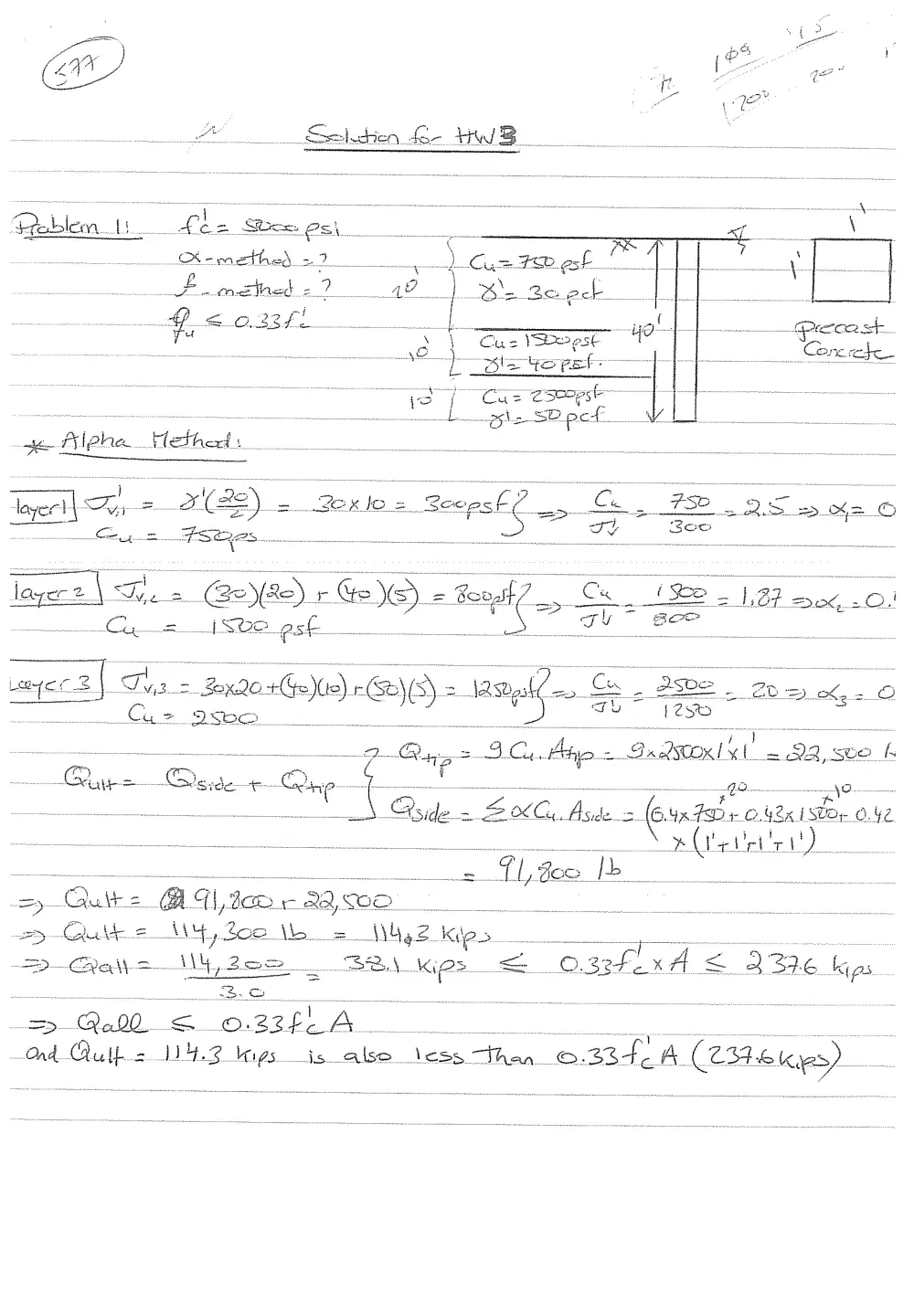
ee 9B — 3, Ais « 7 a 9 aston = 24, GO Lh
renee cerns ene {eo — male a
xO, Abide = am (eux dabe ©, ASa i Or. oO. Ne
_ i Beer)
—- “Outre, Bt q \, 302 + re xo, 0D. ce vec os
By Cauatte =AN aw 302. \bo... ANG, 2. kilo ae sen os
=>. Cae |r M42 ae 32, \ Kies <= O.32Fe KF f < a) 37.6 Kips
=> Aclh os O.22f A. .
Ord Quills 42 keys is also tess than ©.33424. (2eBetes)
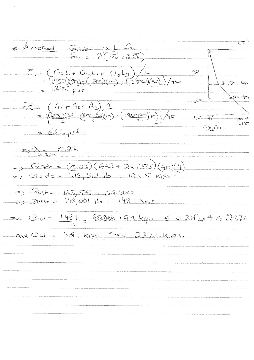
if. _ mathe ~ Aside oor el Ley
Laws ACT. 22 Se)
~CGs a Ca, cla, Cals te a
= Tasn}on)3( SDL OLS fs ae
ae IBIS sf ten
The (Arr fer As) A
= (8 + (Gee ie\( 2). ea ie Spor septa) ny) \ Ve
Z- ~ na
=> Catia 4a Faee% uqa hope. < omflsAt < Qe26
Cable, mo as ene
a Qua edge ——— a ao ate gr a | £ _
To etna ann _ ¥
Cais, = ok i. A
Tp. Kh a. -
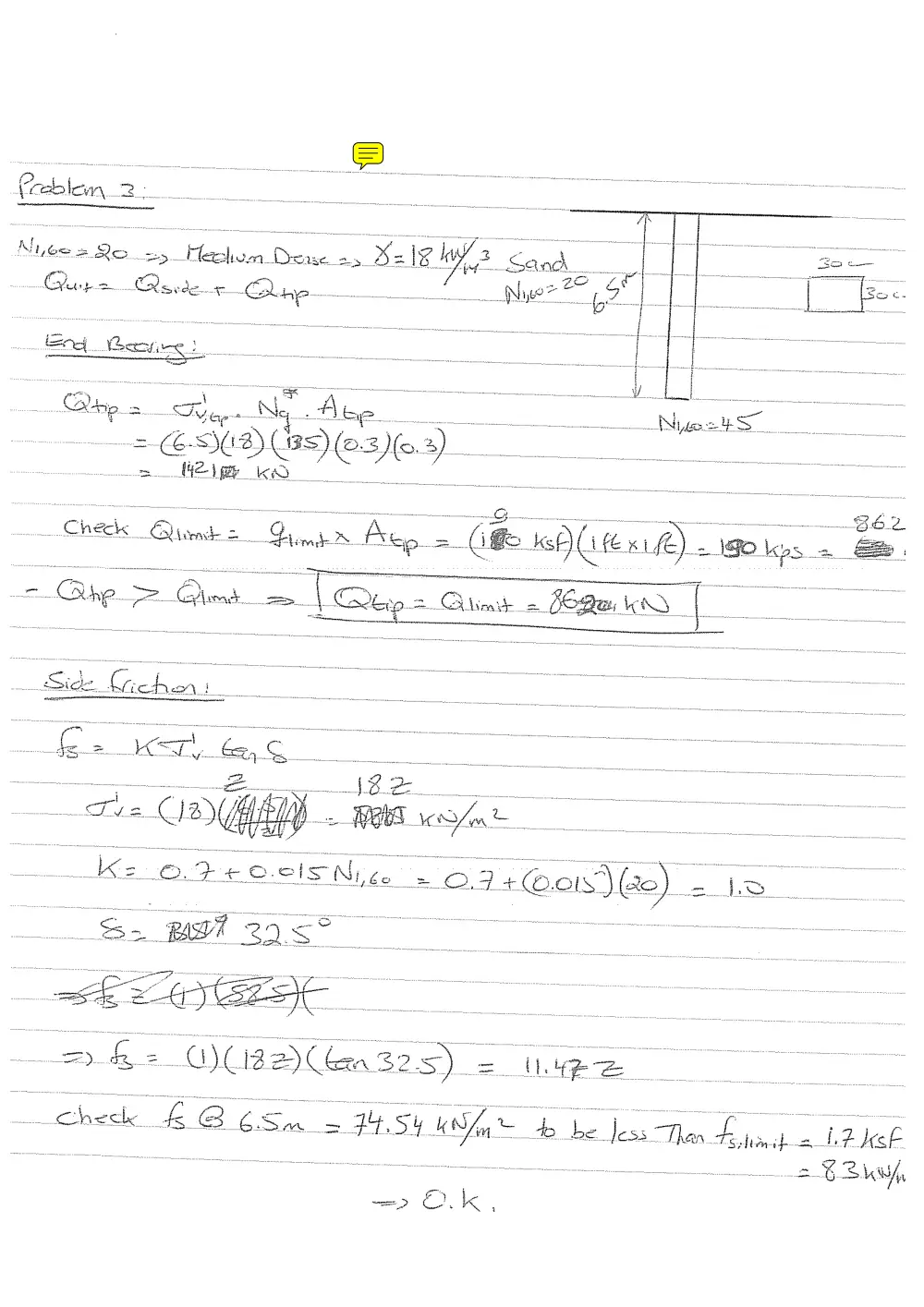
Mae Ney fe tn Niece S stanton
f on
Ls Cé- <2) ENCSI ay tei -
HER KO i
. : = ; _ a aed st unatecirt tt stent i ign e
mek. — oS
eck Odom = = — Hn mike 2 n be gp = (if. sf) ad (exif) . 2 I8O\os =. Se.
: check | k a 6S = T4.54 uf L b x : Jess Than - f hitn 7 af iP heb
st _— = %2 Zw,
SL
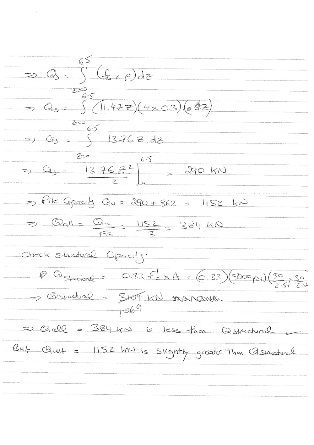
> Ose) Giteanoaleda)
6 7 _. - —
=) Gis x 4 ISG cao Az
ee a
> Gye 1297625) 2 ao kW
: sn Ro, BD enon i en
=> Pile Gpaahy. @a2 Bo+ 262 = Use Ld -
ED. Dott = & a Se 254 LER / /
Check SAO Cape cite i i
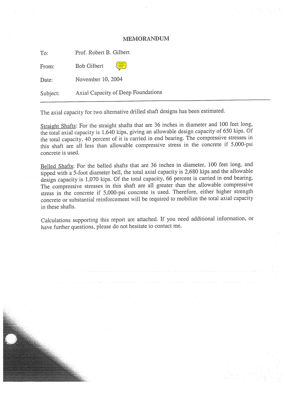
MEMORANDUM
To: Prof. Robert B. Gilbert
From: Bob Gilbert S
Date: November 10, 2004
Subject: Axial Capacity of Deep Foundations
The axial capacity for two alternative drilled shaft designs has been estimated.
Straight Shafts: For the straight shafts that are 36 inches in diameter and 100 feet long,
the total axial capacity is 1,640 kips, giving an allowable design capacity of 650 kips. Of
the total capacity, 40 percent of it is carried in end bearing. The compressive stresses in
this shaft are all less than allowable compressive stress in the concrete if 5,000-psi
concrete is used.
Belled Shafts: For the belled shafts that are 36 inches in diameter, 100 feet long, and
tipped with a 5-foot diameter bell, the total axial capacity is 2,680 kips and the allowable
design capacity is 1,070 kips. Of the total capacity, 66 percent is carried in end bearing.
The compressive stresses in this shaft are all greater than the allowable compressive
stress in the concrete if 5,000-psi concrete is used. Therefore, either higher strength
concrete or substantial reinforcement will be required to mobilize the total axial capacity
in these shafts.
Calculations supporting this report are attached. If you need additional information, or
have further questions, please do not hesitate to contact me.
&
;
2
“k
€
eae
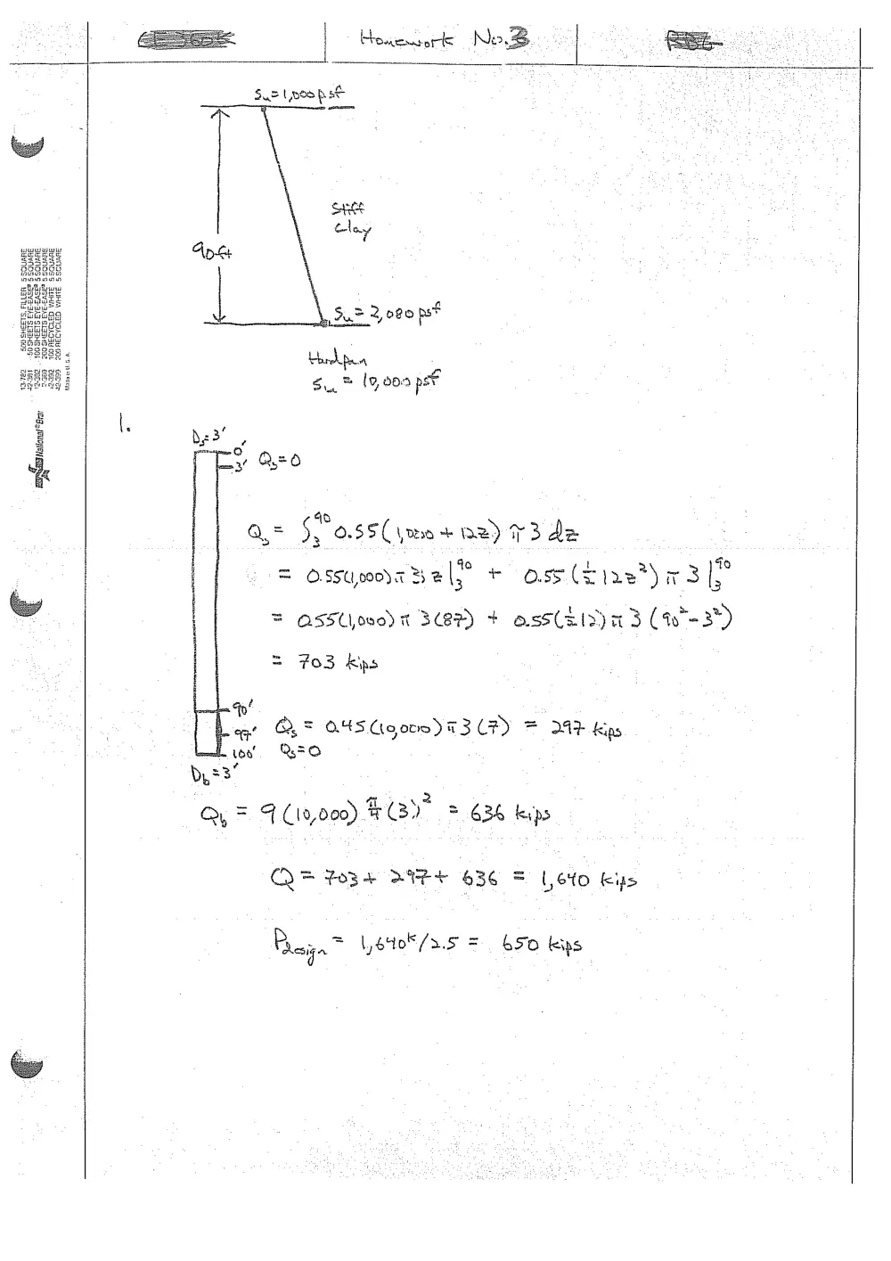
a= $3 0.55( m0 + oz) 73 de
ossupooda Bel} + oss (fire) a3|P
I
= ASSUoeo) x 3A + oss(hinn3 (a*-3)
= 703 kps
og! OQ, = O45 Coors) 73 UF) = “242 kins
it 2
Q, = F (10,000) C32 = G34 kvps
CQQ> FoR+ BIF+ 636 = Loto Kus
Raga \,6408/3.5 = 50 kis
Homework No |
sapeastona Brar
ey
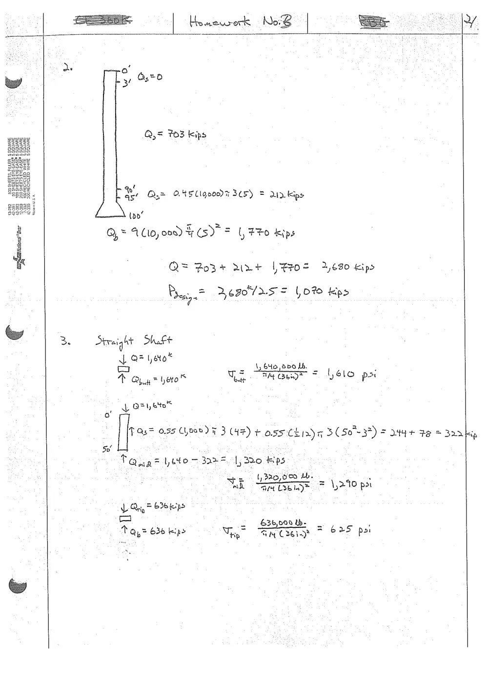
Q,= 703 Kips
cf
| &, Qs= ONSLlyc00% 305) = Up Kips
tao’
Q = A Cto, oos) ty (sy = (, #%0 kips
Q= Poss r+ | Feo= 2,680 Kips
Phen %690°/ 2.5 = L070 kps
3. Straight Shaft
xf Q* eto* - 4
co = So Sbo Lb. = .
Poygcyuo’ GE ORME = SLO ps
a QE, bo
a!
_ TOs= 055 Chooe) F 3 (47) y¢ O55 CEIn) AH 3 (50-37) = 244+ Fe = 320
50” :
Tag = yeto ~ 3a>=. |, B20 Hips
= 1 22G, CO Me .
Nak GM Leeiag™ = \y>10 par
1 Qn, * 3b fips
oa : 636,000 Ub. .
t Qy > 635 ipo ra = m Ose > 625 posi
sips
tu
Ue ces work No. & |
E
he
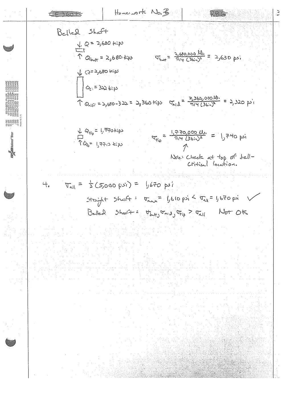
Bethe She
aL. Q ® 2630 teips
tr
VP Qh F 2,680 kyo
wt QE A,6FO eps
Qe. = 30D. ks po
T Oso =>,p20-322% 2 3E0 Ripe Tea ATSC
L &.,7 1,770 kips
oO
| TQu= 22 Epo
4 Tar = FCSoa0 ps) =
2,480,085 hb.
- 2S .
That = Ty (3e* a 2,630 ps:
2 Bob, 000 hb.
faa hetiste aataneten 1 ‘
2 = 2,320 pot
{
270,000 LL. .
a a ad \,#4o psi
Shp TM CBG inD*
‘a
Nestet Cheeta act top ot bell-
Critical location.
670 psi
Stott Shalt? T= Golo pst Ty= betopi VO
0
Betle®R — Sha +
hats Teed y ip 7 Thy
Not OF