
EECE 210 Homework 10 with Solution, Fall 2013
American University of Beirut · Electric Circuits · 5 pages · with solution

More EECE 210 files
Show the text of this homework
Homework 10
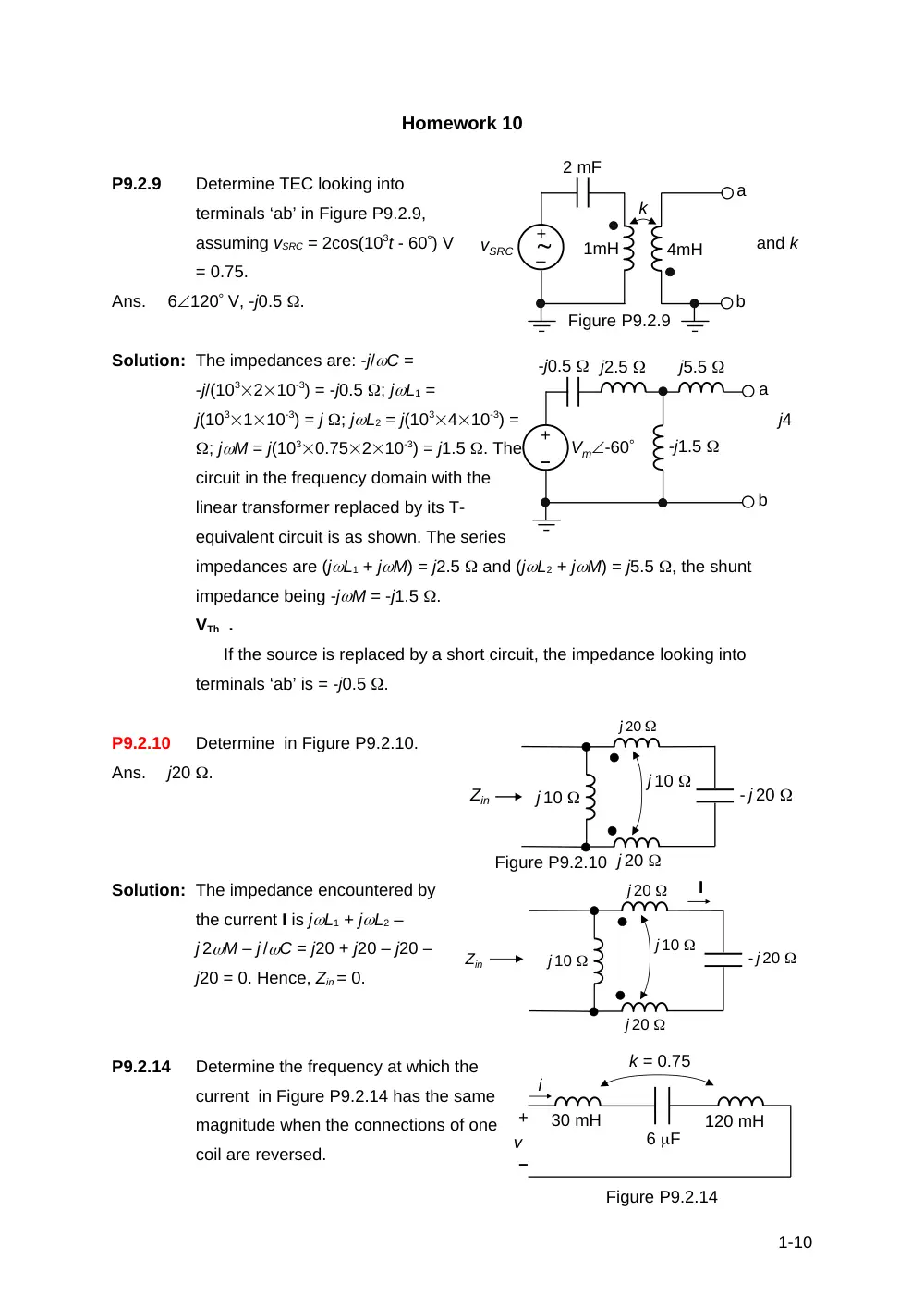
P9.2.9
Determine TEC looking into
terminals ‘ab’ in Figure P9.2.9,
assuming vSRC = 2cos(103t - 60) V
and k
= 0.75.
Ans.
6120 V, -j0.5 .
Solution: The impedances are: -j/C =
-j/(103210-3) = -j0.5 ; jL1 =
j(103110-3) = j ; jL2 = j(103410-3) =
j4
; jM = j(1030.75210-3) = j1.5 . The
circuit in the frequency domain with the
linear transformer replaced by its T-
equivalent circuit is as shown. The series
impedances are (jL1 + jM) = j2.5 and (jL2 + jM) = j5.5 , the shunt
impedance being -jM = -j1.5 .
VTh .
If the source is replaced by a short circuit, the impedance looking into
terminals ‘ab’ is = -j0.5 .
P9.2.10
Determine in Figure P9.2.10.
Ans.
j20 .
Solution: The impedance encountered by
the current I is jL1 + jL2 –
j 2M – j /C = j20 + j20 – j20 –
j20 = 0. Hence, Zin = 0.
P9.2.14
Determine the frequency at which the
current in Figure P9.2.14 has the same
magnitude when the connections of one
coil are reversed.
1-10
vSRC
k
1mH
4mH
2 mF
a
b
Figure P9.2.9
–
+
–
+
Vm-60
-j0.5
a
b
j2.5
j5.5
-j1.5
j 20
j 10
j 20
j 10
- j 20
Figure P9.2.10
Zin
j 20
j 10
j 20
j 10
- j 20
Zin
I
30 mH
120 mH
6 F
k = 0.75
+
–
v
i
Figure P9.2.14
Solution: M 0.75 45 mH. Since the current magnitude remains the same when one coil
is reversed, the impedance reverses sign. Thus: j(30 + 120 + 90) – -j(30 +
120 - 90) + , or 300 . 2 ; krad/s.
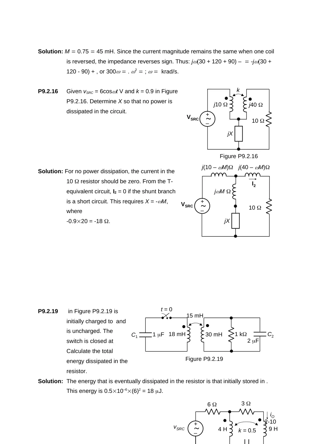
P9.2.16
Given vSRC = 6cost V and k = 0.9 in Figure
P9.2.16. Determine X so that no power is
dissipated in the circuit.
Solution: For no power dissipation, the current in the
10 resistor should be zero. From the T-
equivalent circuit, I2 = 0 if the shunt branch
is a short circuit. This requires X = -M,
where
-0.920 = -18 .
P9.2.19
in Figure P9.2.19 is
initially charged to and
is uncharged. The
switch is closed at
Calculate the total
energy dissipated in the
resistor.
Solution: The energy that is eventually dissipated in the resistor is that initially stored in .
This energy is 0.510–6(6)2 = 18 J.
2-10
k
j10
10
VSRC
Figure P9.2.16
j40
jX
–
+
j(10 – M)
10
VSRC
jM
jX
–
+
j(40 – M)
I2
15 mH
30 mH
18 mH
1 k
1 F
2 F
C1
t = 0
C2
Figure P9.2.19
6
3
k = 0.5
9 H
iO
4 H
vSRC
–
+
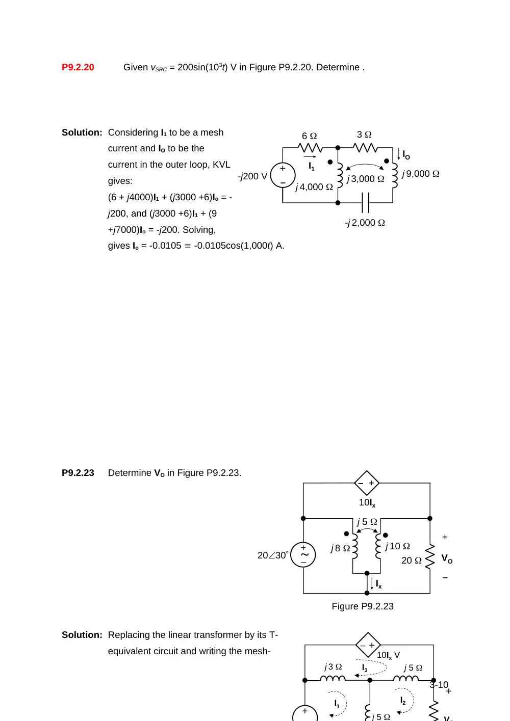
P9.2.20
Given vSRC = 200sin(103t) V in Figure P9.2.20. Determine .
Solution: Considering I1 to be a mesh
current and IO to be the
current in the outer loop, KVL
gives:
(6 + j4000)I1 + (j3000 +6)Io = -
j200, and (j3000 +6)I1 + (9
+j7000)Io = -j200. Solving,
gives Io = -0.0105 -0.0105cos(1,000t) A.
P9.2.23
Determine VO in Figure P9.2.23.
Solution: Replacing the linear transformer by its T-
equivalent circuit and writing the mesh-
3-10
6
–
+
3
IO
j 4,000
-j200 V
j 9,000
-j 2,000
j 3,000
I1
j 5
j 8
j 10
20
10Ix
Ix
2030
– +
+
–
VO
Figure P9.2.23
–
+
j 5
j 3
10Ix V
+
– +
+
V
j 5
I3
I1
I2
current equations:
j8I1 – j5I2 – j3I3 2030,
-j5I1 + (20 + j10)I2 – j5I3 0,
-j3I1 – j5I2 + j8I3 10(I1 – I2),
or, -(10 + j3)I1 + (10 – j5)I2 + j8I3 0.
Solving, I2 0.897 – j0.777 A; hence, VO = 20I2 = 17.94 – j15.53 V.
P9.2.24
Given V in Figure P9.2.24.
Determine .
Solution: j500210–3 = j ; j500810–3
= j4 ; mH; j5003.210–3 =
j1.6 ;
4-10
10 F
10
k = 0.8
5
8 mH
2 mH
iO
vSRC
Figure P9.2.24
–
+
10
5
–
+
IO
j 2.4
-j 200
500
j 1.6
-j 0.6
I1
I2
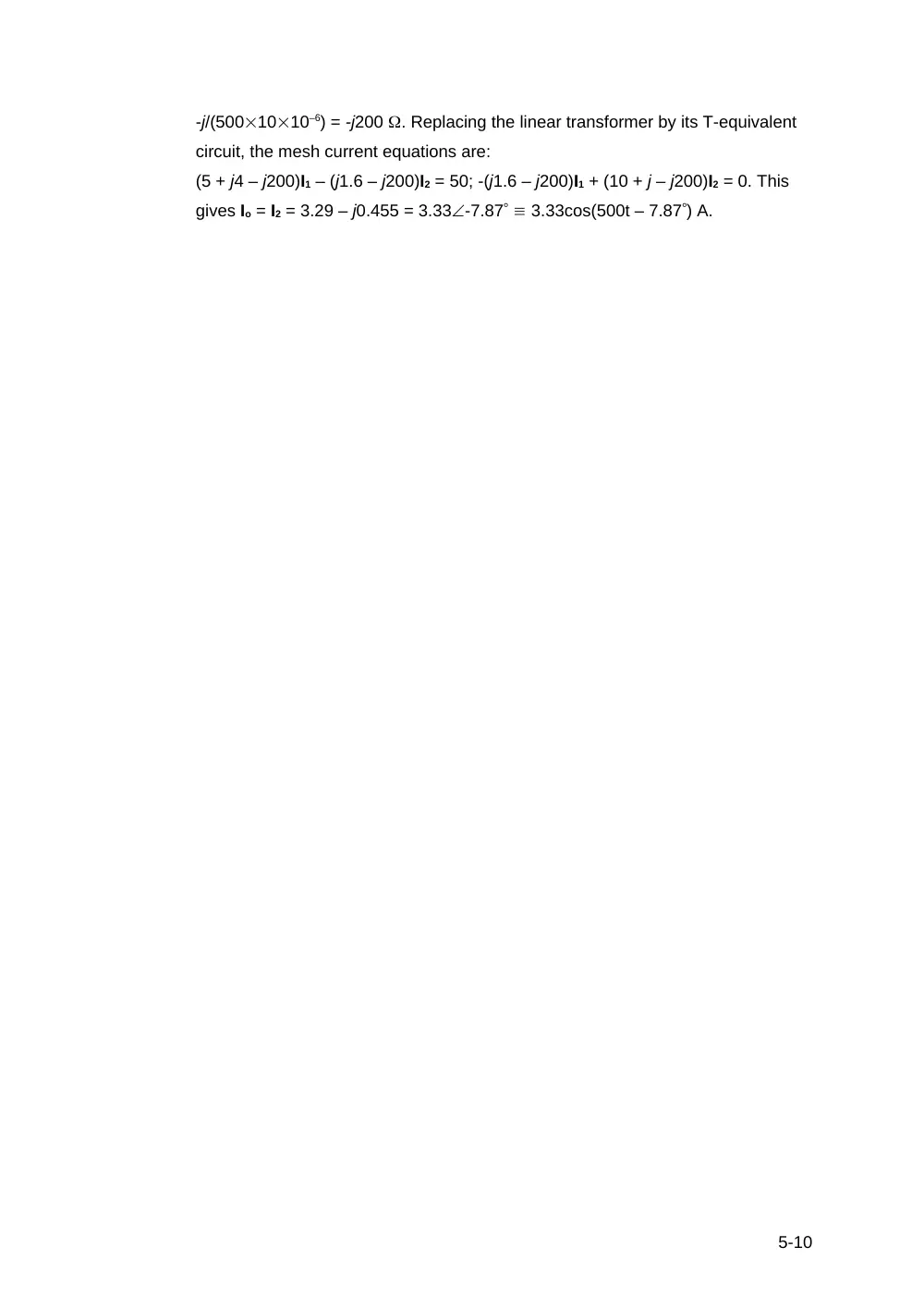
-j/(5001010–6) = -j200 . Replacing the linear transformer by its T-equivalent
circuit, the mesh current equations are:
(5 + j4 – j200)I1 – (j1.6 – j200)I2 = 50; -(j1.6 – j200)I1 + (10 + j – j200)I2 = 0. This
gives Io = I2 = 3.29 – j0.455 = 3.33-7.87 3.33cos(500t – 7.87) A.
5-10