
EECE 210 Homework 11 with Solution, Fall 2014
American University of Beirut · Electric Circuits · 5 pages · with solution
More EECE 210 files
Show the text of this homework
1:2
1200 V
8
1:4
–
+
20
8
20
+
–
VO
I
VO/20
VO/20 – I
+
–
VO – 20I
4I
+
–
(32I + VO/4
VO/4)
+
–
8I
(16I +
VO/8)
+
–
VO/20 – 9I
+ 2VO/5 – 72I
–
Homework 11
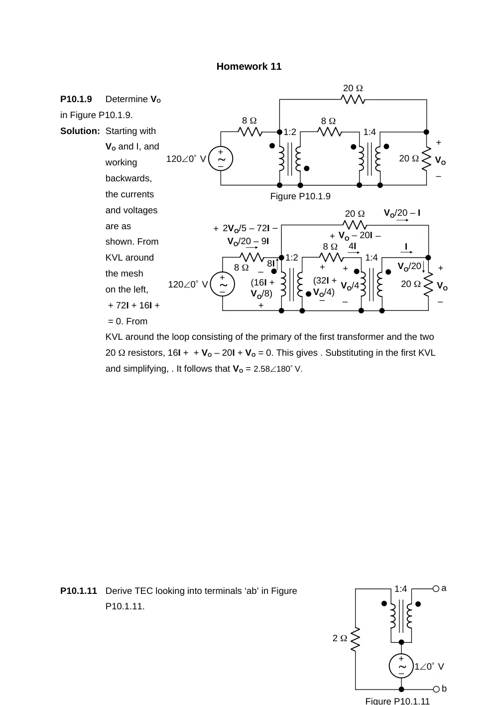
P10.1.9
Determine VO
in Figure P10.1.9.
Solution: Starting with
VO and I, and
working
backwards,
the currents
and voltages
are as
shown. From
KVL around
the mesh
on the left,
+ 72I + 16I +
= 0. From
KVL around the loop consisting of the primary of the first transformer and the two
20 resistors, 16I + + VO – 20I + VO = 0. This gives . Substituting in the first KVL
and simplifying, . It follows that VO = 2.58180 V.
P10.1.11
Derive TEC looking into terminals ‘ab’ in Figure
P10.1.11.
1:2
1200 V
Figure P10.1.9
8
1:4
–
+
20
8
20
+
–
VO
1:4
2
Figure P10.1.11
10 V
a
b
–
+
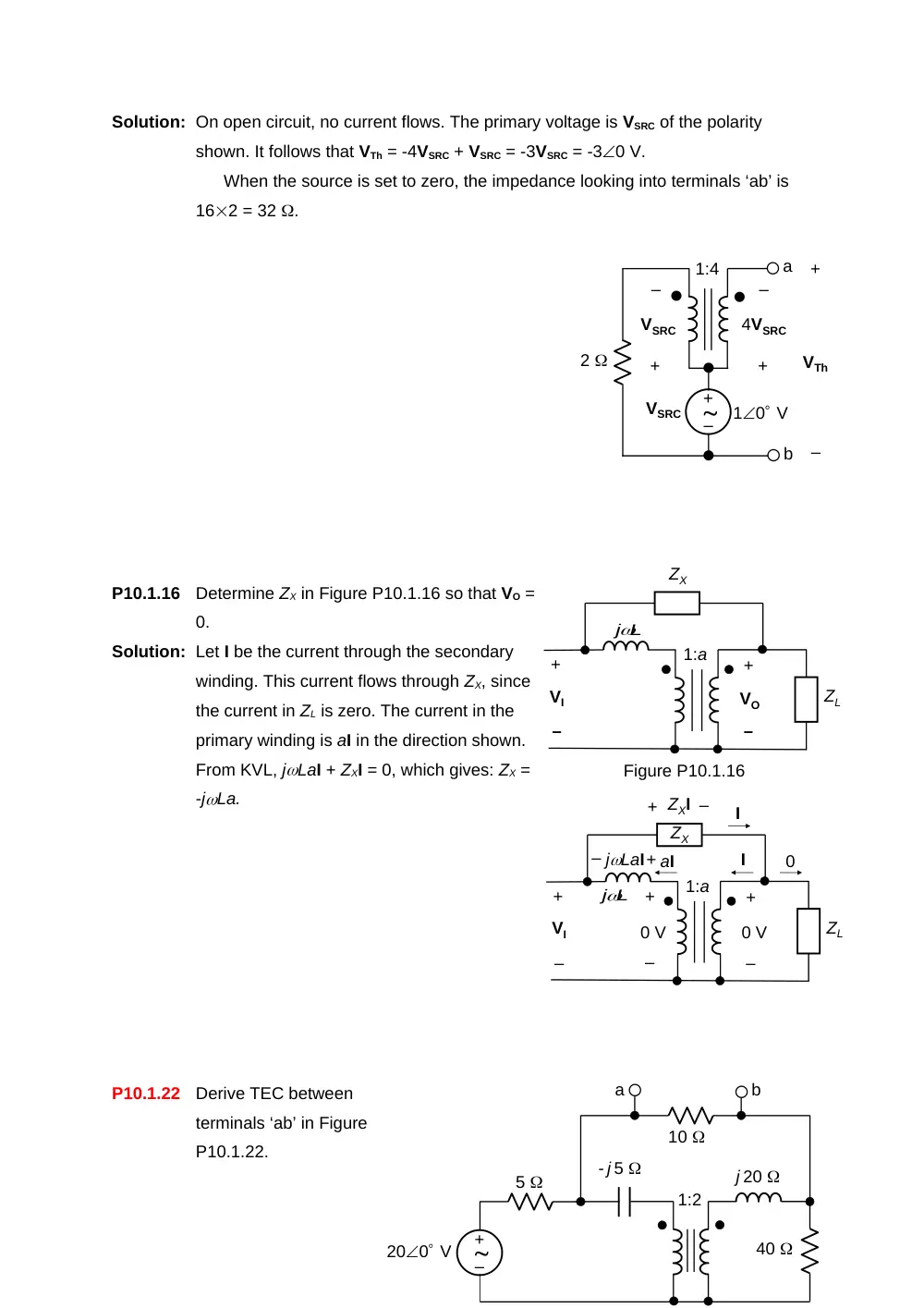
Solution: On open circuit, no current flows. The primary voltage is VSRC of the polarity
shown. It follows that VTh = -4VSRC + VSRC = -3VSRC = -30 V.
When the source is set to zero, the impedance looking into terminals ‘ab’ is
162 = 32 .
P10.1.16
Determine ZX in Figure P10.1.16 so that VO =
0.
Solution: Let I be the current through the secondary
winding. This current flows through ZX, since
the current in ZL is zero. The current in the
primary winding is aI in the direction shown.
From KVL, jLaI + ZXI = 0, which gives: ZX =
-jLa.
P10.1.22
Derive TEC between
terminals ‘ab’ in Figure
P10.1.22.
1:4
2
10 V
a
b
–
+
VSRC
+
–
4VSRC
+
–
VSRC
+
–
VTh
+
–
VO
ZL
+
–
VI
ZX
L
j
1:a
Figure P10.1.16
+
–
0 V
+
–
VI
ZX
L
j
1:a
+
–
0 V
I
aI
I
+
jLaI
ZL
0
–
+
–
ZXI
200 V
5
- j 5
1:2
j 20
40
10
b
a
–
+
200 V
5
- j 5
1:2
j 20
40
b
a
–
+
+
–
V1
+
–
2V1
I
2I
2I + Isc
Isc
I + Isc
40(I + Isc)
+
–
40(I + Isc)
+
–
Isc
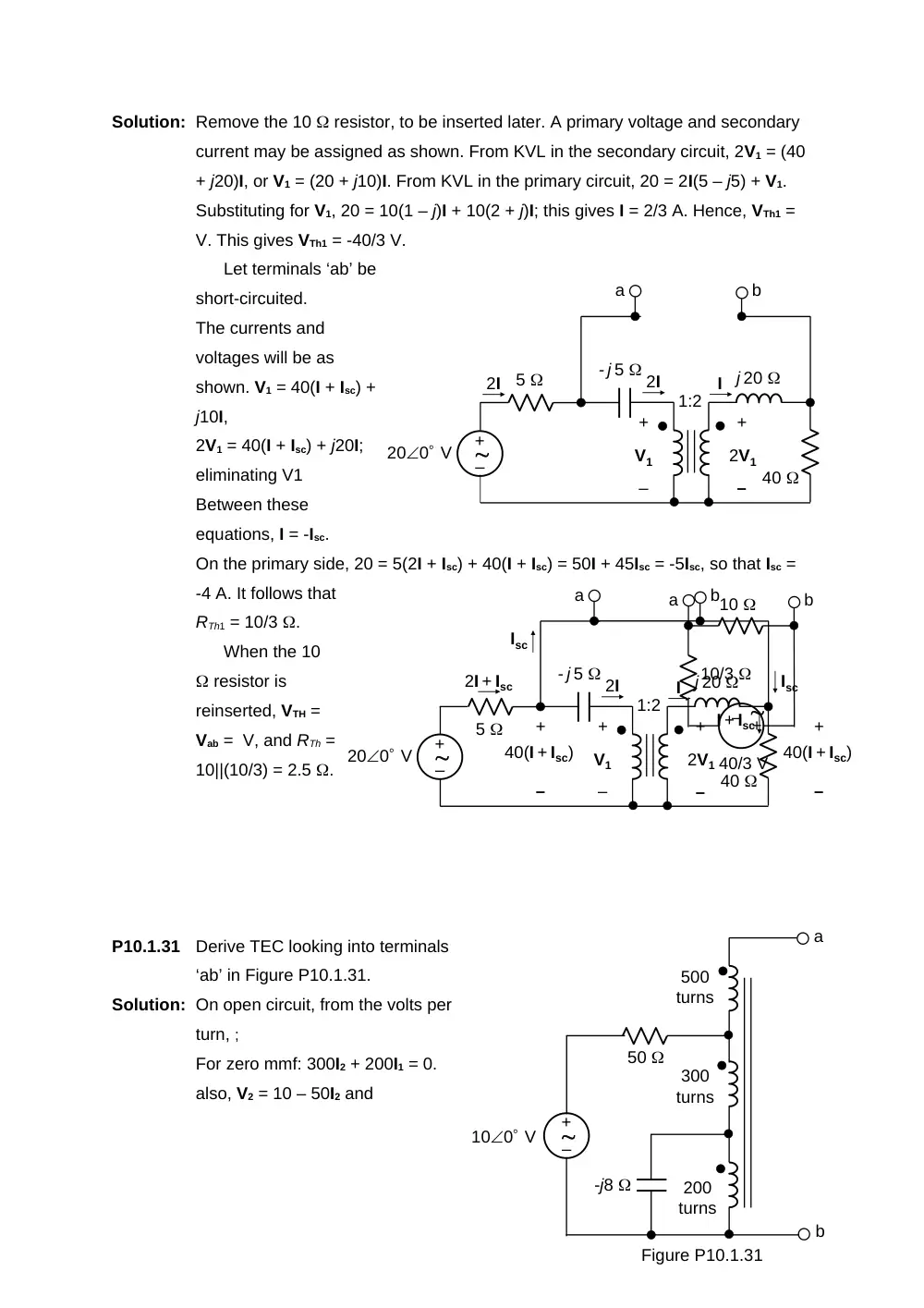
Solution: Remove the 10 resistor, to be inserted later. A primary voltage and secondary
current may be assigned as shown. From KVL in the secondary circuit, 2V1 = (40
+ j20)I, or V1 = (20 + j10)I. From KVL in the primary circuit, 20 = 2I(5 – j5) + V1.
Substituting for V1, 20 = 10(1 – j)I + 10(2 + j)I; this gives I = 2/3 A. Hence, VTh1 =
V. This gives VTh1 = -40/3 V.
Let terminals ‘ab’ be
short-circuited.
The currents and
voltages will be as
shown. V1 = 40(I + Isc) +
j10I,
2V1 = 40(I + Isc) + j20I;
eliminating V1
Between these
equations, I = -Isc.
On the primary side, 20 = 5(2I + Isc) + 40(I + Isc) = 50I + 45Isc = -5Isc, so that Isc =
-4 A. It follows that
RTh1 = 10/3 .
When the 10
resistor is
reinserted, VTH =
Vab = V, and RTh =
10||(10/3) = 2.5 .
P10.1.31
Derive TEC looking into terminals
‘ab’ in Figure P10.1.31.
Solution: On open circuit, from the volts per
turn, ;
For zero mmf: 300I2 + 200I1 = 0.
also, V2 = 10 – 50I2 and
200 V
5
- j 5
1:2
j 20
40
b
a
–
+
+
–
V1
+
–
2V1
I
2I
2I
b
a
–
+
40/3 V
10/3
10
500
turns
300
turns
Figure P10.1.31
100 V
200
turns
-j8
a
b
50
–
+
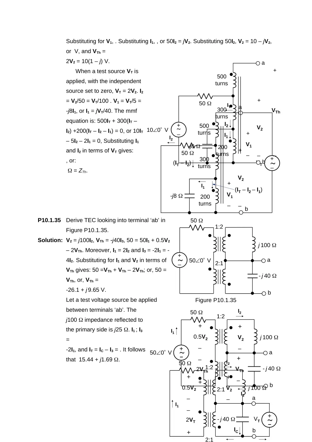
Substituting for V1, . Substituting I1, , or 50I2 = jV2. Substituting 50I2, V2 = 10 – jV2,
or V, and VTh =
2V2 = 10(1 – j) V.
When a test source VT is
applied, with the independent
source set to zero, VT = 2V2. I2
= V2/50 = VT/100 . V1 = VT/5 =
-j8I1, or I1 = jVT/40. The mmf
equation is: 500IT + 300(IT –
I2) +200(IT – I2 – I1) = 0, or 10IT
– 5I2 – 2I1 = 0, Substituting I1
and I2 in terms of VT gives:
, or:
= ZTh.
P10.1.35
Derive TEC looking into terminal ‘ab’ in
Figure P10.1.35.
Solution: V2 = j100I2, VTh = j40I3, 50 = 50I1 + 0.5V2
– 2VTh. Moreover, I1 = 2I2 and I3 = -2I1 = -
4I2. Substituting for I1 and V2 in terms of
VTh gives: 50 =VTh + VTh – 2VTh; or, 50 =
VTh, or, VTh =
-26.1 + j 9.65 V.
Let a test voltage source be applied
between terminals ‘ab’. The
j100 impedance reflected to
the primary side is j25 . I1 ; I3
=
-2I1, and IT = IC – I3 = . It follows
that 15.44 + j1.69 .
500
turns
300
turns
200
turns
-j8
a
b
50
–
+
IT
I2
I1
+
–
V2
+
–
V1
(IT – I2)
(IT – I2 – I1)
VT
500 V
50
j 100
- j 40
1:2
2:1
a
b
Figure P10.1.35
–
+
–
+
500 V
50
j 100
- j 40
1:2
2:1
a
b
+
–
0.5V2
+
–
V2
+
–
VTh
+
–
2VTh
I2
I1
I3
50
j 100
- j 40
1:2
2:1
a
b
+
–
0.5V2
+
–
V2
+
–
2VT
I2
–
+
VT
I1
IC
500
turns
300
turns
100 V
200
turns
-j8
a
b
50
–
+
+
–
V2
+
–
VTh
+
–
V1
I1
I2
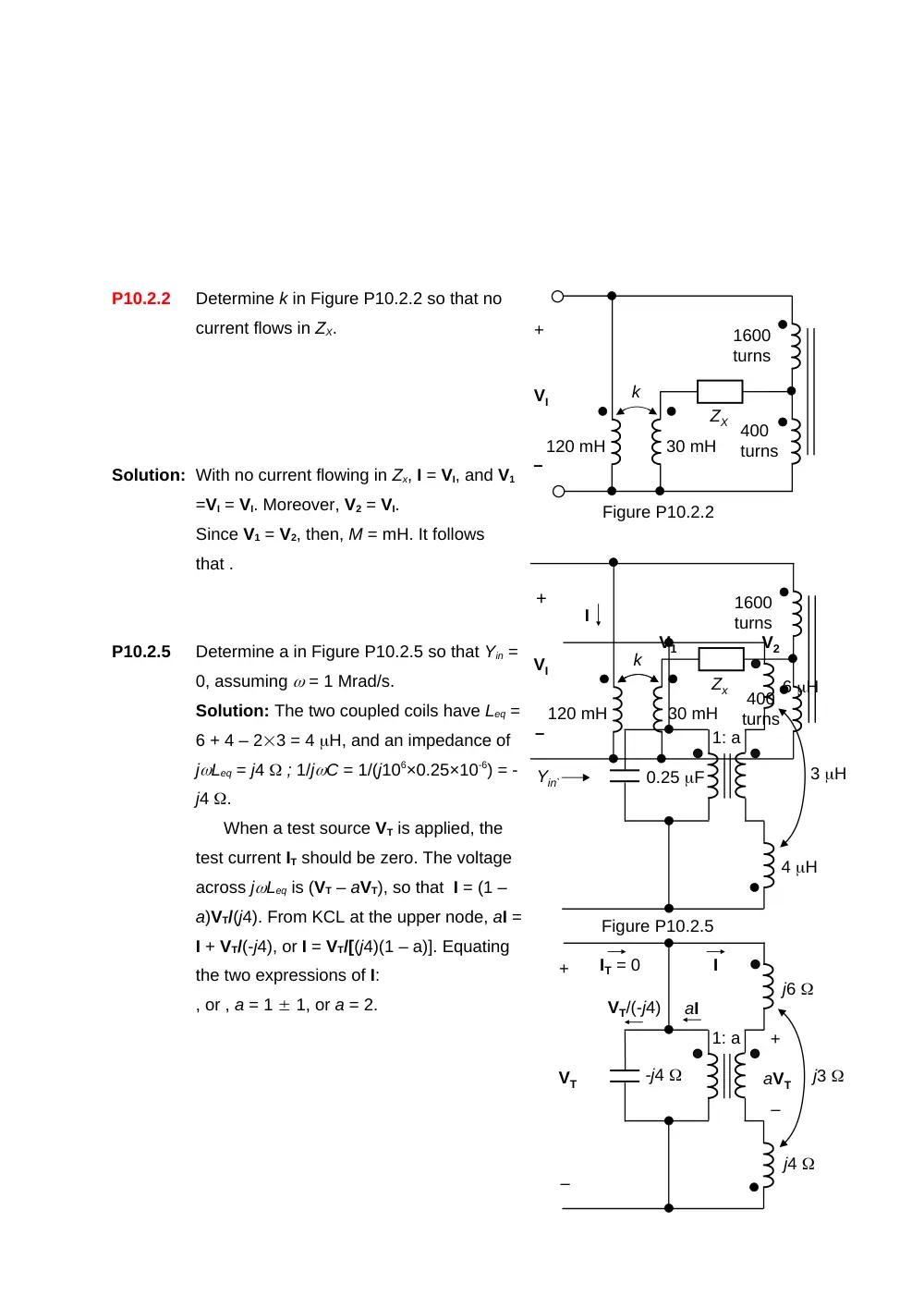
P10.2.2
Determine k in Figure P10.2.2 so that no
current flows in ZX.
Solution: With no current flowing in Zx, I = VI, and V1
=VI = VI. Moreover, V2 = VI.
Since V1 = V2, then, M = mH. It follows
that .
P10.2.5
Determine a in Figure P10.2.5 so that Yin =
0, assuming = 1 Mrad/s.
Solution: The two coupled coils have Leq =
6 + 4 – 23 = 4 H, and an impedance of
jLeq = j4 ; 1/jC = 1/(j106×0.25×10-6) = -
j4 .
When a test source VT is applied, the
test current IT should be zero. The voltage
across jLeq is (VT – aVT), so that I = (1 –
a)VT/(j4). From KCL at the upper node, aI =
I + VT/(-j4), or I = VT/[(j4)(1 – a)]. Equating
the two expressions of I:
, or , a = 1 1, or a = 2.
Zx
120 mH
30 mH
k
1600
turns
400
turns
+
–
VI
I
V1
V2
ZX
VI
120 mH
30 mH
k
1600
turns
400
turns
+
–
Figure P10.2.2
6 H
1: a
Yin`
Figure P10.2.5
0.25 F
3 H
4 H
j6
1: a
–
+
VT
j3
j4
–
+
aVT
I
aI
IT = 0
-j4
VT/(-j4)