
EECE 210 Homework 12 with Solution, Fall 2014
American University of Beirut · Electric Circuits · 3 pages · with solution
More EECE 210 files
Show the text of this homework
+
–
30 V
8 k
ic
+
–
75 V
160 k
40 k
Va
Homework12
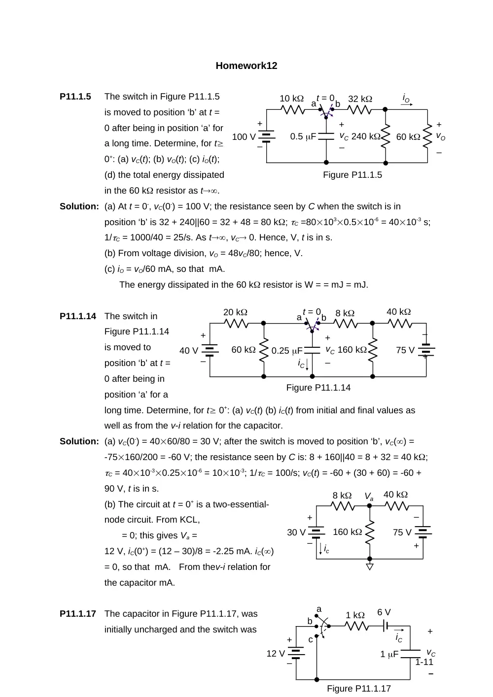
P11.1.5
The switch in Figure P11.1.5
is moved to position ‘b’ at t =
0 after being in position ‘a’ for
a long time. Determine, for t
0+: (a) vC(t); (b) vO(t); (c) iO(t);
(d) the total energy dissipated
in the 60 k resistor as t.
Solution: (a) At t = 0-, vC(0-) = 100 V; the resistance seen by C when the switch is in
position ‘b’ is 32 + 240||60 = 32 + 48 = 80 k; C =801030.510-6 = 4010-3 s;
1/C = 1000/40 = 25/s. As t, vC 0. Hence, V, t is in s.
(b) From voltage division, vO = 48vC/80; hence, V.
(c) iO = vO/60 mA, so that mA.
The energy dissipated in the 60 k resistor is W = = mJ = mJ.
P11.1.14
The switch in
Figure P11.1.14
is moved to
position ‘b’ at t =
0 after being in
position ‘a’ for a
long time. Determine, for t 0+: (a) vC(t) (b) iC(t) from initial and final values as
well as from the v-i relation for the capacitor.
Solution: (a) vC(0-) = 4060/80 = 30 V; after the switch is moved to position ‘b’, vC() =
-75160/200 = -60 V; the resistance seen by C is: 8 + 160||40 = 8 + 32 = 40 k;
C = 4010-30.2510-6 = 1010-3; 1/C = 100/s; vC(t) = -60 + (30 + 60) = -60 +
90 V, t is in s.
(b) The circuit at t = 0+ is a two-essential-
node circuit. From KCL,
= 0; this gives Va =
12 V, iC(0+) = (12 – 30)/8 = -2.25 mA. iC()
= 0, so that mA. From thev-i relation for
the capacitor mA.
P11.1.17
The capacitor in Figure P11.1.17, was
initially uncharged and the switch was
1-11
60 k
+
–
100 V
0.5 F
240 k
32 k
10 k a
b
+
–
+
–
vC
vO
iO
Figure P11.1.5
t = 0
60 k
+
–
40 V
0.25 F
8 k
20 k
a
b
+
–
vC
iC
Figure P11.1.14
+
–
75 V
160 k
40 k
t = 0
+
1 k
1 F
vC
12 V
6 V
a
b
c
iC
–
Figure P11.1.17
+
–
in position ‘a’. At the switch is moved to position ‘b’. Determine for t ≥ 0+: (a) vC(t);
(b) iC(t); (c) the energy delivered by the 12 V battery as t (d) the energy
absorbed by the 6 V battery as t; (e) the energy dissipated in the resistor as
t; verify this by integrating the power dissipated by iC from t = 0+ to t; (f) If
after a long time, t′ = 0, the switch is moved to position c, determinevC(t) andiC(t)
for t′ 0+, the energy delivered by the 6 V battery, the energy gained or lost by
the capacitor, and the energy dissipated in the resistor.
Solution: (a) vC(0-) = 0;. vC() = 6 V. = 11 = 1 ms. Hence, vC = V, tis in ms;
(b) iC(0+) = (12 – 6)/1 = 6 mA; iC() = 0; mA.
(c) Energy delivered by the 12 V battery is = = 72 J as t.
(d) Energy absorbed by the 6V battery is =36J as t.
(e) As t, net energy delivered by the two batteries is 36 J. Energy stored in
capacitor is (1/2)10-636 = 18 J.Energy dissipated in the resistor = 36 – 18
= 18 J= 18 J.
(f) For t 0, initial value of vC is 6 V, final value is -6 V, being the same.
Hence, V; initial value of iC is -12/1 mA, final value is zero;. As , energy
delivered by the battery is = 72 J; net energy lost by the capacitor is 18 – 18
= 0, energy dissipated in the resistor is J.
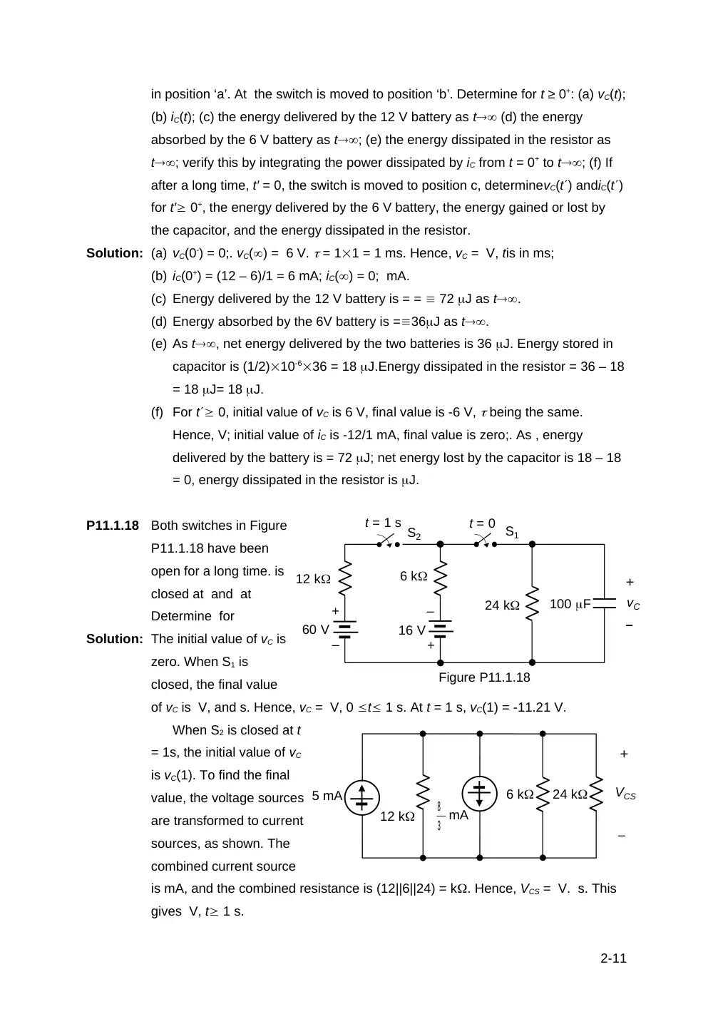
P11.1.18
Both switches in Figure
P11.1.18 have been
open for a long time. is
closed at and at
Determine for
Solution: The initial value of vC is
zero. When S1 is
closed, the final value
of vC is V, and s. Hence, vC = V, 0 t 1 s. At t = 1 s, vC(1) = -11.21 V.
When S2 is closed at t
= 1s, the initial value of vC
is vC(1). To find the final
value, the voltage sources
are transformed to current
sources, as shown. The
combined current source
is mA, and the combined resistance is (12||6||24) = k. Hence, VCS = V. s. This
gives V, t 1 s.
2-11
6 k
24 k
+
–
VCS
mA
5 mA
12 k
3
8
12 k
60 V
6 k
16 V
t = 1 s S2
t = 0 S1
24 k
100 F
+
–
vC
Figure P11.1.18
+
–
+
–
10 mA
30 k
5 k
20 nF
10 k
2 k
a
S1
b
+
–
vC
S2
Figure P11.1.19
t = 0
t = 50 s
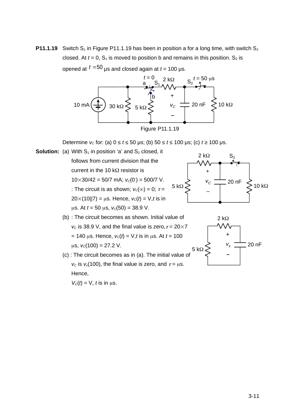
P11.1.19
Switch S1 in Figure P11.1.19 has been in position a for a long time, with switch S2
closed. At t = 0, S1 is moved to position b and remains in this position. S2 is
opened at
μs and closed again at t = 100 μs.
Determine vC for: (a) 0 ≤ t ≤ 50 μs; (b) 50 ≤ t ≤ 100 μs; (c) t ≥ 100 μs.
Solution: (a) With S1 in position ‘a’ and S2 closed, it
follows from current division that the
current in the 10 k resistor is
1030/42 = 50/7 mA; vC(0-) = 500/7 V.
: The circuit is as shown; vC() = 0; =
20(10||7) = s. Hence, vC(t) = V,t is in
s. At t = 50 s, vC(50) = 38.9 V.
(b) : The circuit becomes as shown. Initial value of
vC is 38.9 V, and the final value is zero, = 207
= 140 s. Hence, vC(t) = V,t is in s. At t = 100
s, vC(100) = 27.2 V.
(c) : The circuit becomes as in (a). The initial value of
vC is vx(100), the final value is zero, and = s.
Hence,
VC(t) = V, t is in s.
3-11
5 k
20 nF
2 k
+
–
vx
5 k
20 nF
10 k
2 k
+
–
vC
S2
t 50