
EECE 210 Homework 13 with Solution, Fall 2013
American University of Beirut · Electric Circuits · 4 pages · with solution
More EECE 210 files
Show the text of this homework
Homework 13
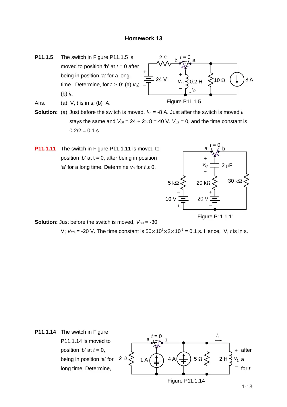
P11.1.5
The switch in Figure P11.1.5 is
moved to position ‘b’ at t = 0 after
being in position ‘a’ for a long
time. Determine, for t 0: (a) vO;
(b) iO.
Ans.
(a) V, t is in s; (b) A.
Solution: (a) Just before the switch is moved, IL0 = -8 A. Just after the switch is moved iL
stays the same and VL0 = 24 + 28 = 40 V. VLS = 0, and the time constant is
0.2/2 = 0.1 s.
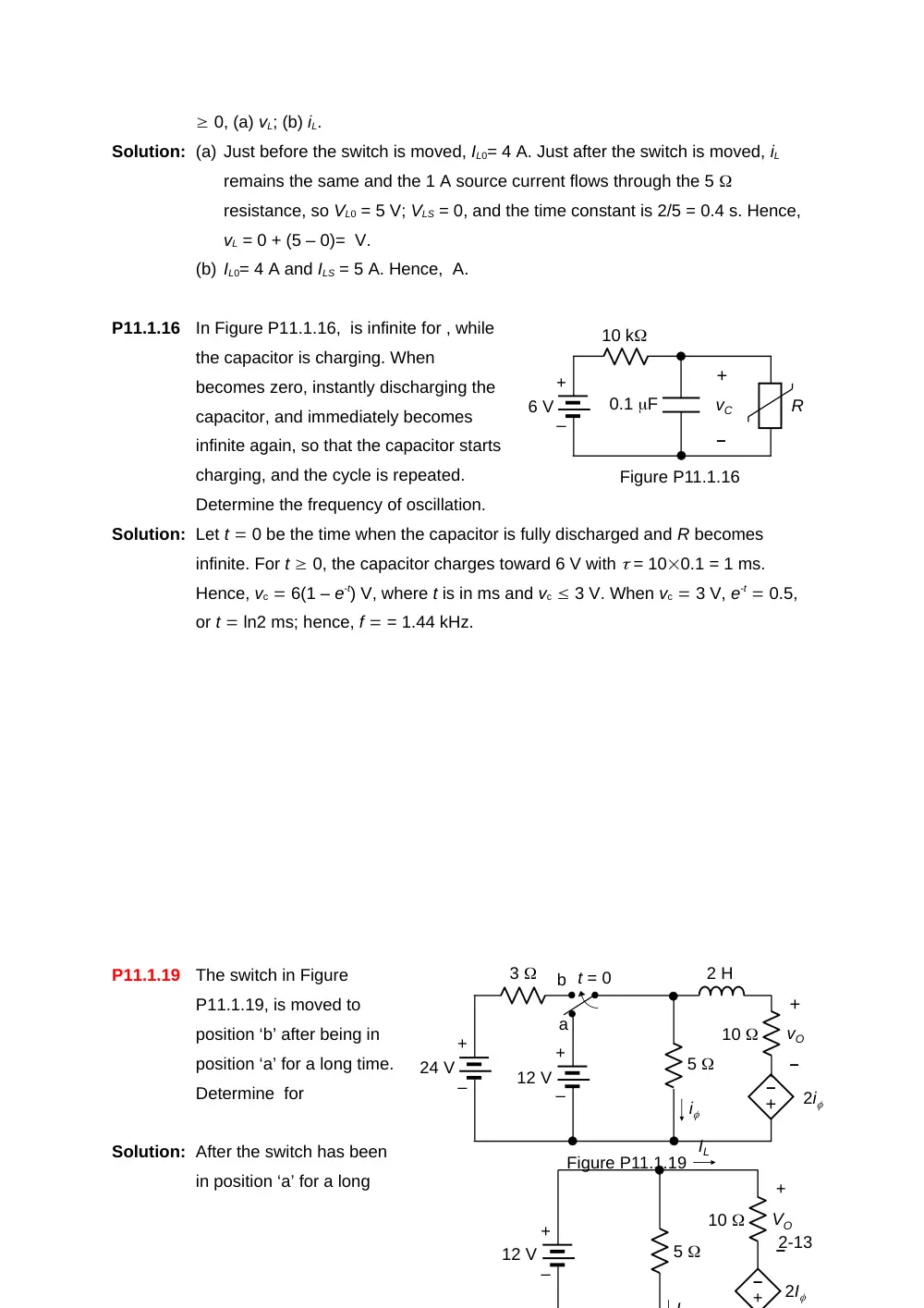
P11.1.11
The switch in Figure P11.1.11 is moved to
position ‘b’ at t = 0, after being in position
‘a’ for a long time. Determine vC for t ≥ 0.
Solution: Just before the switch is moved, VC0 = -30
V; VCS = -20 V. The time constant is 50103210-6 = 0.1 s. Hence, V, t is in s.
P11.1.14
The switch in Figure
P11.1.14 is moved to
position ‘b’ at t = 0,
after
being in position ‘a’ for
a
long time. Determine,
for t
1-13
0.2 H
+
–
10
2
+
–
vO
iO
Figure P11.1.5
24 V
t = 0
8 A
a
b
+
–
Figure P11.1.11
20 V
20 k
+
–
10 V
a t = 0
b
30 k
5 k
2 F
–
+
vC
+
–
vL
Figure P11.1.14
2
5
t = 0
1 A
iL
4 A
2 H
a
b
0, (a) vL; (b) iL.
Solution: (a) Just before the switch is moved, IL0= 4 A. Just after the switch is moved, iL
remains the same and the 1 A source current flows through the 5
resistance, so VL0 = 5 V; VLS = 0, and the time constant is 2/5 = 0.4 s. Hence,
vL = 0 + (5 – 0)= V.
(b) IL0= 4 A and ILS = 5 A. Hence, A.
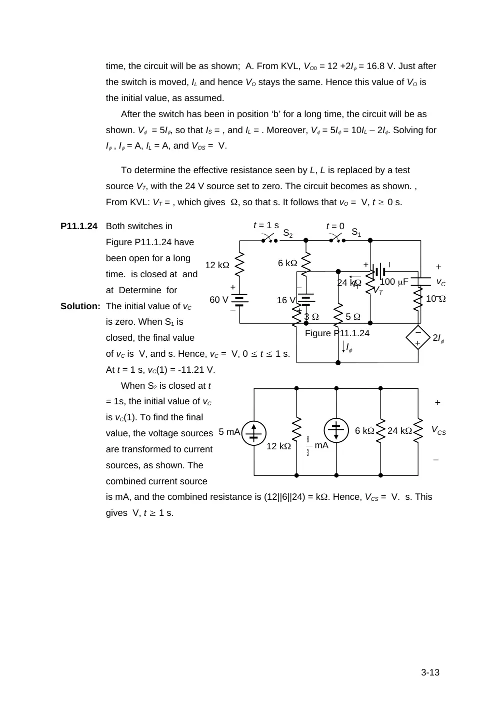
P11.1.16
In Figure P11.1.16, is infinite for , while
the capacitor is charging. When
becomes zero, instantly discharging the
capacitor, and immediately becomes
infinite again, so that the capacitor starts
charging, and the cycle is repeated.
Determine the frequency of oscillation.
Solution: Let t 0 be the time when the capacitor is fully discharged and R becomes
infinite. For t 0, the capacitor charges toward 6 V with = 100.1 = 1 ms.
Hence, vc 6(1 – e-t) V, where t is in ms and vc 3 V. When vc 3 V, e-t 0.5,
or t ln2 ms; hence, f = 1.44 kHz.
P11.1.19
The switch in Figure
P11.1.19, is moved to
position ‘b’ after being in
position ‘a’ for a long time.
Determine for
Solution: After the switch has been
in position ‘a’ for a long
2-13
10 k
0.1 F
+
–
vC
R
6 V
Figure P11.1.16
+
–
+
–
vO
3
24 V
5
10
2 H
12 V
–
+
t = 0
i
2i
a
b
Figure P11.1.19
+
–
+
–
+
–
VO
5
10
12 V
–
+
I
2I
+
–
IL
time, the circuit will be as shown; A. From KVL, VO0 = 12 +2I = 16.8 V. Just after
the switch is moved, IL and hence VO stays the same. Hence this value of VO is
the initial value, as assumed.
After the switch has been in position ‘b’ for a long time, the circuit will be as
shown. V = 5I, so that IS = , and IL = . Moreover, V = 5I = 10IL – 2I. Solving for
I , I = A, IL = A, and VOS = V.
To determine the effective resistance seen by L, L is replaced by a test
source VT, with the 24 V source set to zero. The circuit becomes as shown. ,
From KVL: VT = , which gives , so that s. It follows that vO = V, t 0 s.
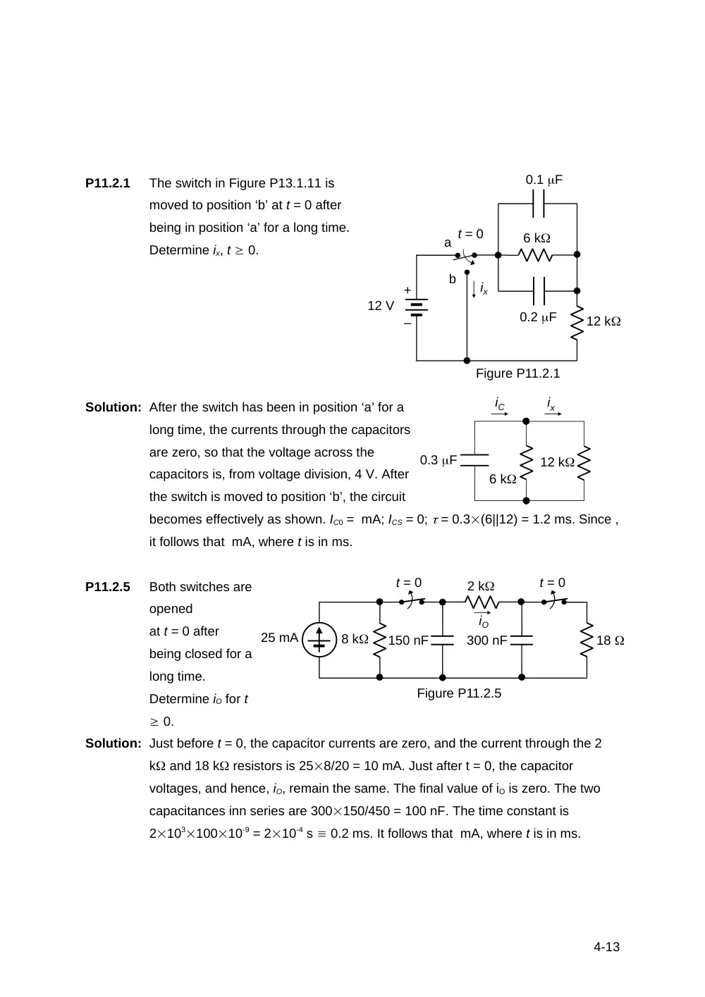
P11.1.24
Both switches in
Figure P11.1.24 have
been open for a long
time. is closed at and
at Determine for
Solution: The initial value of vC
is zero. When S1 is
closed, the final value
of vC is V, and s. Hence, vC = V, 0 t 1 s.
At t = 1 s, vC(1) = -11.21 V.
When S2 is closed at t
= 1s, the initial value of vC
is vC(1). To find the final
value, the voltage sources
are transformed to current
sources, as shown. The
combined current source
is mA, and the combined resistance is (12||6||24) = k. Hence, VCS = V. s. This
gives V, t 1 s.
3-13
5
10
–
+
2I
VT
IT
I
3
+
–
12 k
60 V
6 k
16 V
t = 1 s S2
t = 0 S1
24 k
100 F
+
–
vC
Figure P11.1.24
+
–
+
–
6 k
24 k
+
–
VCS
mA
5 mA
12 k
3
8
P11.2.1
The switch in Figure P13.1.11 is
moved to position ‘b’ at t = 0 after
being in position ‘a’ for a long time.
Determine ix, t 0.
Solution: After the switch has been in position ‘a’ for a
long time, the currents through the capacitors
are zero, so that the voltage across the
capacitors is, from voltage division, 4 V. After
the switch is moved to position ‘b’, the circuit
becomes effectively as shown. IC0 = mA; ICS = 0; = 0.3(6||12) = 1.2 ms. Since ,
it follows that mA, where t is in ms.
P11.2.5
Both switches are
opened
at t = 0 after
being closed for a
long time.
Determine iO for t
0.
Solution: Just before t = 0, the capacitor currents are zero, and the current through the 2
k and 18 k resistors is 258/20 = 10 mA. Just after t = 0, the capacitor
voltages, and hence, iO, remain the same. The final value of iO is zero. The two
capacitances inn series are 300150/450 = 100 nF. The time constant is
210310010-9 = 210-4 s 0.2 ms. It follows that mA, where t is in ms.
4-13
12 V
6 k
0.1 F
0.2 F
12 k
ix
t = 0
a
b
Figure P11.2.1
+
–
12 k
ix
6 k
0.3 F
iC
t = 0
t = 0
18
8 k
Figure P11.2.5
2 k
25 mA
300 nF
150 nF
iO