
EECE 210 Homework 14 with Solution, Fall 2014
American University of Beirut · Electric Circuits · 7 pages · with solution
More EECE 210 files
Show the text of this homework
Homework 14
P12.1.9
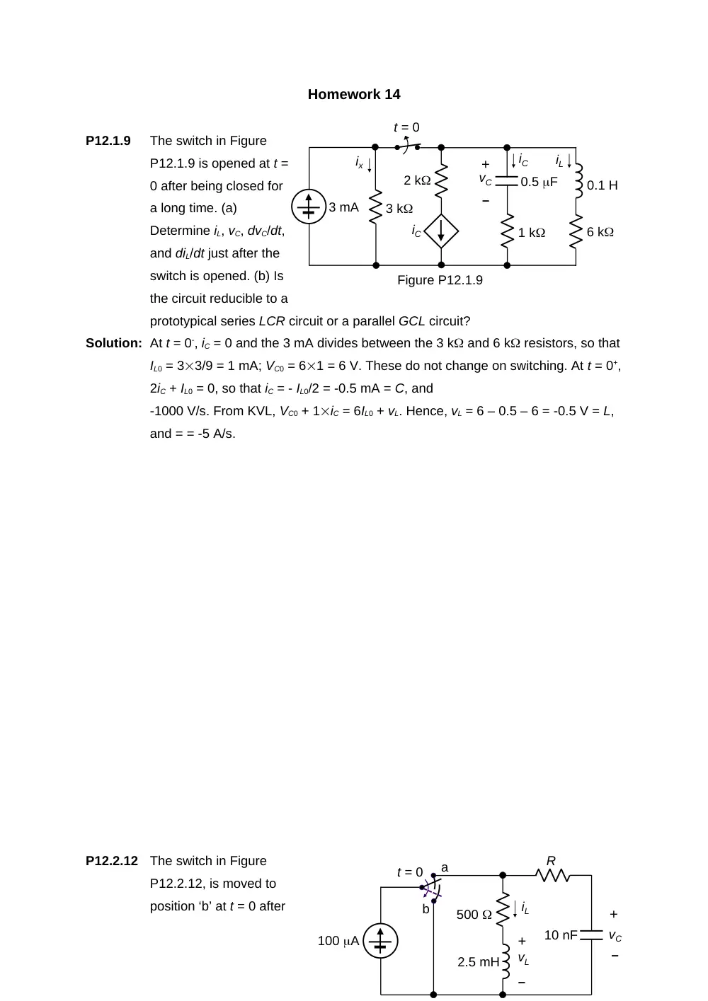
The switch in Figure
P12.1.9 is opened at t =
0 after being closed for
a long time. (a)
Determine iL, vC, dvC/dt,
and diL/dt just after the
switch is opened. (b) Is
the circuit reducible to a
prototypical series LCR circuit or a parallel GCL circuit?
Solution: At t = 0-, iC = 0 and the 3 mA divides between the 3 k and 6 k resistors, so that
IL0 = 33/9 = 1 mA; VC0 = 61 = 6 V. These do not change on switching. At t = 0+,
2iC + IL0 = 0, so that iC = - IL0/2 = -0.5 mA = C, and
-1000 V/s. From KVL, VC0 + 1iC = 6IL0 + vL. Hence, vL = 6 – 0.5 – 6 = -0.5 V = L,
and = = -5 A/s.
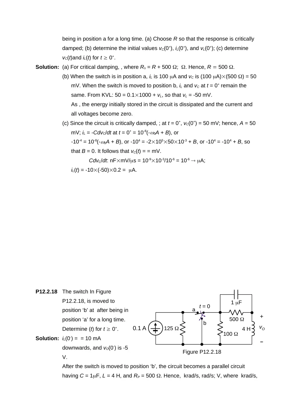
P12.2.12
The switch in Figure
P12.2.12, is moved to
position ‘b’ at t = 0 after
0.5 F
3 k
0.1 H
2 k
iC
+
–
vC
3 mA
iC
iL
ix
6 k
1 k
t = 0
Figure P12.1.9
500
t = 0
+
–
vC
100 A
10 nF
R
2.5 mH
iL
a
b
+
–
vL
500
+
–
vO
125
t = 0
a
b
4 H
100
1 F
0.1 A
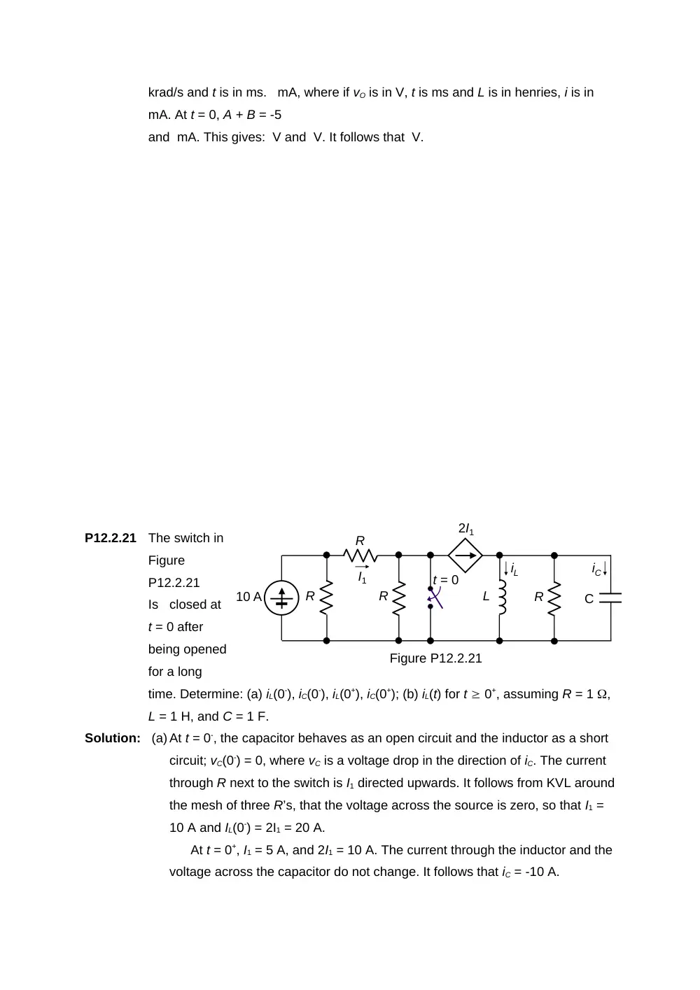
Figure P12.2.18
being in position a for a long time. (a) Choose R so that the response is critically
damped; (b) determine the initial values vC(0+), iL(0+), and vL(0+); (c) determine
vC(t)and iL(t) for t 0+.
Solution: (a) For critical damping, , where Rs = R + 500 ; . Hence, R 500 .
(b) When the switch is in position a, iL is 100 A and vC is (100 A)(500 ) = 50
mV. When the switch is moved to position b, iL and vC at t = 0+ remain the
same. From KVL: 50 = 0.11000 + vL, so that vL = -50 mV.
As , the energy initially stored in the circuit is dissipated and the current and
all voltages become zero.
(c) Since the circuit is critically damped, ; at t = 0+, vC(0+) = 50 mV; hence, A = 50
mV; iL = -CdvC/dt at t = 0+ = 10-8(-0A + B), or
-10-4 = 10-8(-0A + B), or -104 = -21055010-3 + B, or -104 = -104 + B, so
that B = 0. It follows that vC(t) = = mV.
CdvC/dt: nFmV/s = 10-910-3/10-6 = 10-6 A;
iL(t) = -10(-50)0.2 = A.
P12.2.18
The switch In Figure
P12.2.18, is moved to
position ‘b’ at after being in
position ‘a’ for a long time.
Determine (t) for t 0+.
Solution: iL(0-) = = 10 mA
downwards, and vO(0-) is -5
V.
After the switch is moved to position ‘b’, the circuit becomes a parallel circuit
having C = 1F, L = 4 H, and RP = 500 . Hence, krad/s, rad/s; V, where krad/s,
C
iL
R
R
R
R
I1
10 A
t = 0
iC
L
2I1
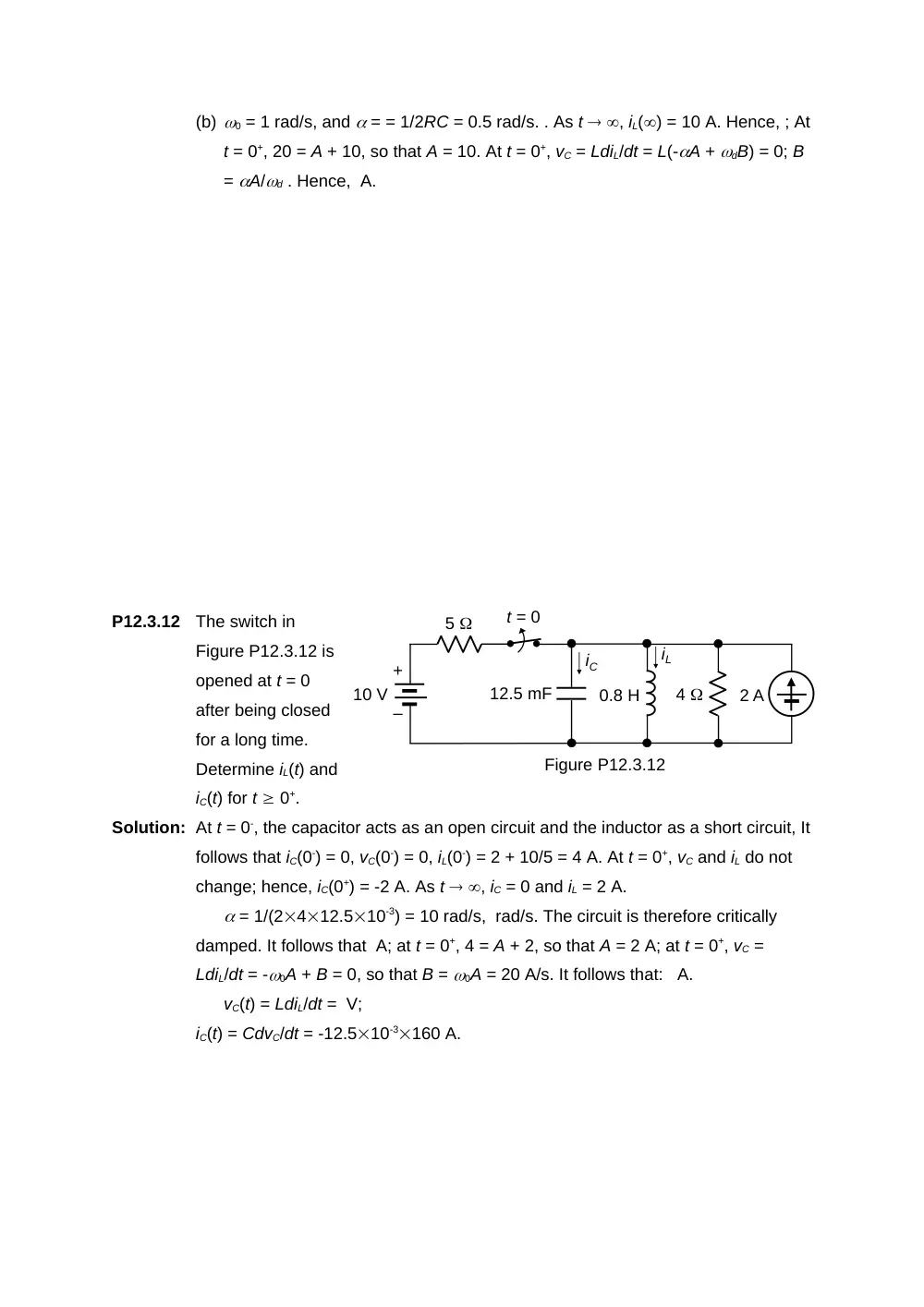
Figure P12.2.21
krad/s and t is in ms. mA, where if vO is in V, t is ms and L is in henries, i is in
mA. At t = 0, A + B = -5
and mA. This gives: V and V. It follows that V.
P12.2.21
The switch in
Figure
P12.2.21
Is closed at
t = 0 after
being opened
for a long
time. Determine: (a) iL(0-), iC(0-), iL(0+), iC(0+); (b) iL(t) for t 0+, assuming R = 1 ,
L = 1 H, and C = 1 F.
Solution: (a) At t = 0-, the capacitor behaves as an open circuit and the inductor as a short
circuit; vC(0-) = 0, where vC is a voltage drop in the direction of iC. The current
through R next to the switch is I1 directed upwards. It follows from KVL around
the mesh of three R’s, that the voltage across the source is zero, so that I1 =
10 A and IL(0-) = 2I1 = 20 A.
At t = 0+, I1 = 5 A, and 2I1 = 10 A. The current through the inductor and the
voltage across the capacitor do not change. It follows that iC = -10 A.
(b) 0 = 1 rad/s, and = = 1/2RC = 0.5 rad/s. . As t , iL() = 10 A. Hence, ; At
t = 0+, 20 = A + 10, so that A = 10. At t = 0+, vC = LdiL/dt = L(-A + dB) = 0; B
= A/d . Hence, A.
P12.3.12
The switch in
Figure P12.3.12 is
opened at t = 0
after being closed
for a long time.
Determine iL(t) and
iC(t) for t 0+.
Solution: At t = 0-, the capacitor acts as an open circuit and the inductor as a short circuit, It
follows that iC(0-) = 0, vC(0-) = 0, iL(0-) = 2 + 10/5 = 4 A. At t = 0+, vC and iL do not
change; hence, iC(0+) = -2 A. As t , iC = 0 and iL = 2 A.
= 1/(2412.510-3) = 10 rad/s, rad/s. The circuit is therefore critically
damped. It follows that A; at t = 0+, 4 = A + 2, so that A = 2 A; at t = 0+, vC =
LdiL/dt = -0A + B = 0, so that B = 0A = 20 A/s. It follows that: A.
vC(t) = LdiL/dt = V;
iC(t) = CdvC/dt = -12.510-3160 A.
iC
10 V
iL
12.5 mF
5
+
–
Figure P12.3.12
t = 0
0.8 H
4
2 A
8
10 H
Figure P12.3.16
t = 0
0.4 F
4
30 A
iL
+
–
vC
t = 0
a
b
5 A
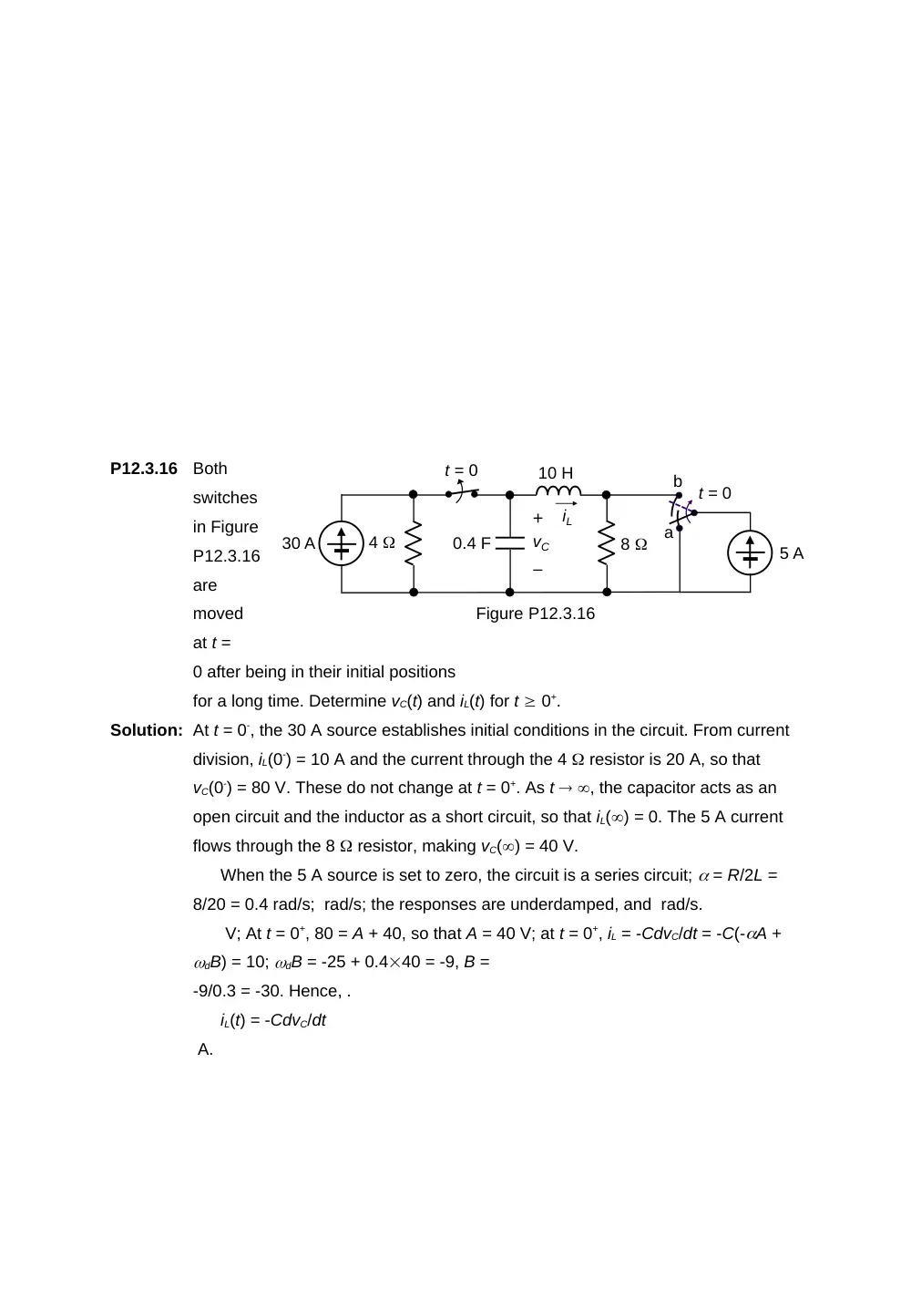
P12.3.16
Both
switches
in Figure
P12.3.16
are
moved
at t =
0 after being in their initial positions
for a long time. Determine vC(t) and iL(t) for t 0+.
Solution: At t = 0-, the 30 A source establishes initial conditions in the circuit. From current
division, iL(0-) = 10 A and the current through the 4 resistor is 20 A, so that
vC(0-) = 80 V. These do not change at t = 0+. As t , the capacitor acts as an
open circuit and the inductor as a short circuit, so that iL() = 0. The 5 A current
flows through the 8 resistor, making vC() = 40 V.
When the 5 A source is set to zero, the circuit is a series circuit; = R/2L =
8/20 = 0.4 rad/s; rad/s; the responses are underdamped, and rad/s.
V; At t = 0+, 80 = A + 40, so that A = 40 V; at t = 0+, iL = -CdvC/dt = -C(-A +
dB) = 10; dB = -25 + 0.440 = -9, B =
-9/0.3 = -30. Hence, .
iL(t) = -CdvC/dt
A.
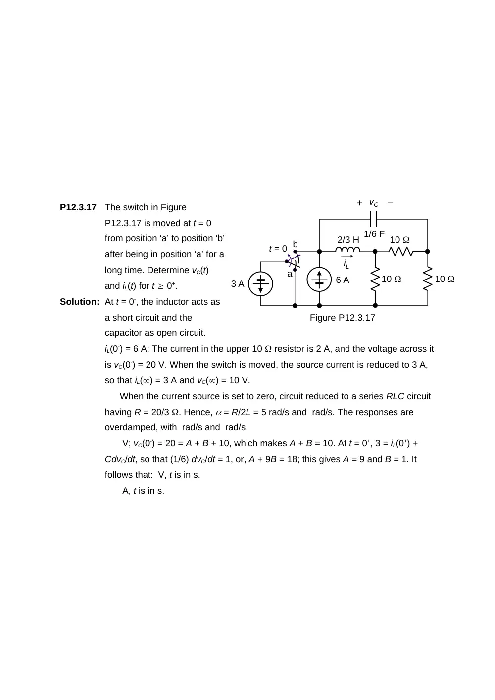
P12.3.17
The switch in Figure
P12.3.17 is moved at t = 0
from position ‘a’ to position ‘b’
after being in position ‘a’ for a
long time. Determine vC(t)
and iL(t) for t 0+.
Solution: At t = 0-, the inductor acts as
a short circuit and the
capacitor as open circuit.
iL(0-) = 6 A; The current in the upper 10 resistor is 2 A, and the voltage across it
is vC(0-) = 20 V. When the switch is moved, the source current is reduced to 3 A,
so that iL() = 3 A and vC() = 10 V.
When the current source is set to zero, circuit reduced to a series RLC circuit
having R = 20/3 . Hence, = R/2L = 5 rad/s and rad/s. The responses are
overdamped, with rad/s and rad/s.
V; vC(0-) = 20 = A + B + 10, which makes A + B = 10. At t = 0+, 3 = iL(0+) +
CdvC/dt, so that (1/6) dvC/dt = 1, or, A + 9B = 18; this gives A = 9 and B = 1. It
follows that: V, t is in s.
A, t is in s.
2/3 H
+
–
vC
Figure P12.3.17
iL
t = 0
3 A
10
a
b
6 A
1/6 F
10
10
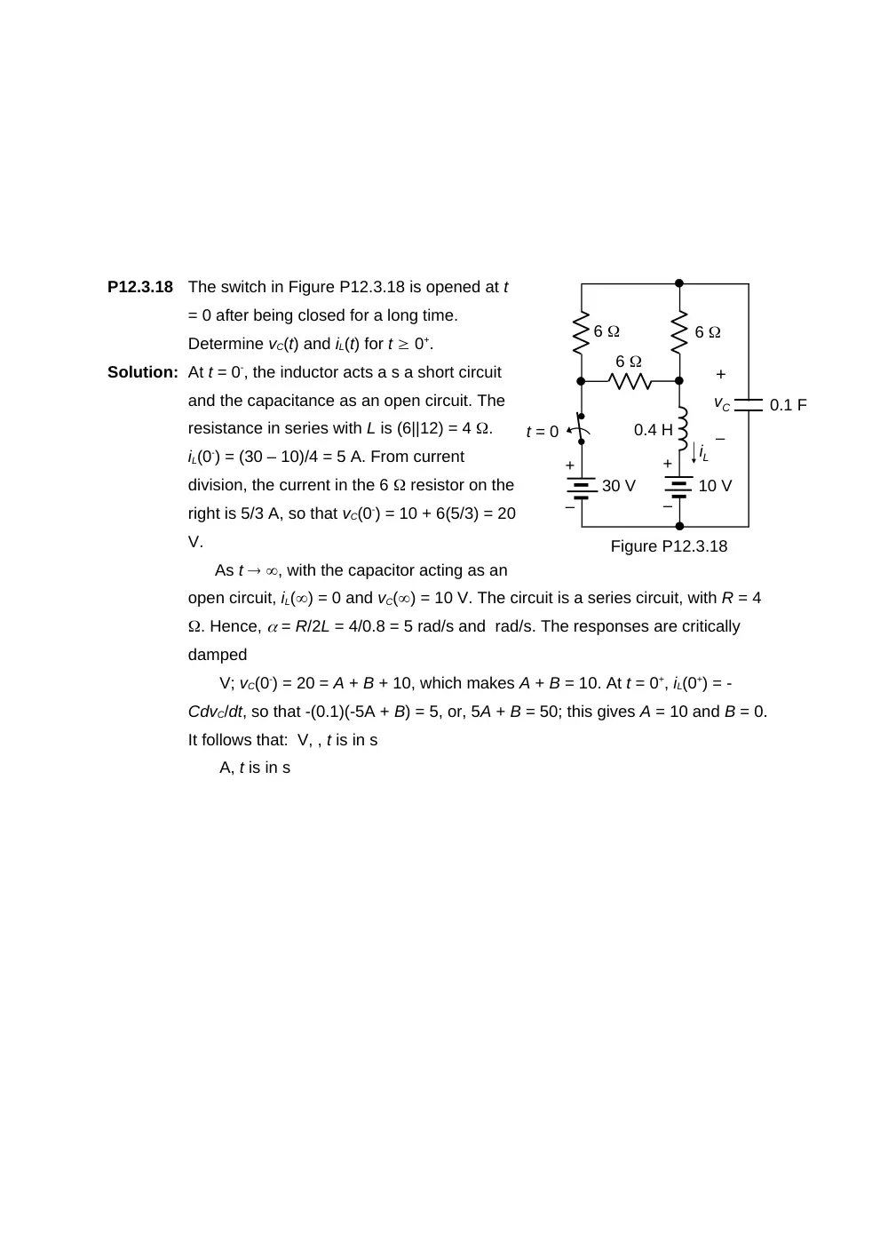
P12.3.18
The switch in Figure P12.3.18 is opened at t
= 0 after being closed for a long time.
Determine vC(t) and iL(t) for t 0+.
Solution: At t = 0-, the inductor acts a s a short circuit
and the capacitance as an open circuit. The
resistance in series with L is (6||12) = 4 .
iL(0-) = (30 – 10)/4 = 5 A. From current
division, the current in the 6 resistor on the
right is 5/3 A, so that vC(0-) = 10 + 6(5/3) = 20
V.
As t , with the capacitor acting as an
open circuit, iL() = 0 and vC() = 10 V. The circuit is a series circuit, with R = 4
. Hence, = R/2L = 4/0.8 = 5 rad/s and rad/s. The responses are critically
damped
V; vC(0-) = 20 = A + B + 10, which makes A + B = 10. At t = 0+, iL(0+) = -
CdvC/dt, so that -(0.1)(-5A + B) = 5, or, 5A + B = 50; this gives A = 10 and B = 0.
It follows that: V, , t is in s
A, t is in s
30 V
iL
0.1 F
+
–
Figure P12.3.18
0.4 H
+
–
vC
+
–
10 V
6
6
6
t = 0