
EECE 210 Homework 2, Fall 2014
American University of Beirut · Electric Circuits · 6 pages

More EECE 210 files
Show the text of this homework
Homework 2
P2.1.4
The current through a resistor is 4sin100t A when the voltage across it is
60sin100t V. Find the resistance and the average power dissipated.
Solution: ; ; W.
P2.1.5
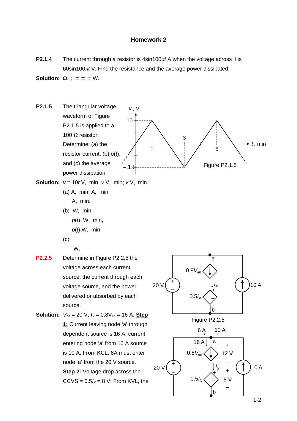
The triangular voltage
waveform of Figure
P2.1.5 is applied to a
100 resistor.
Determine: (a) the
resistor current, (b) p(t),
and (c) the average
power dissipation.
Solution: v = 10t V, min; v V, min; v V, min.
(a) A, min; A, min;
A, min.
(b) W, min,
p(t) W, min,
p(t) W, min.
(c)
W.
P2.2.5
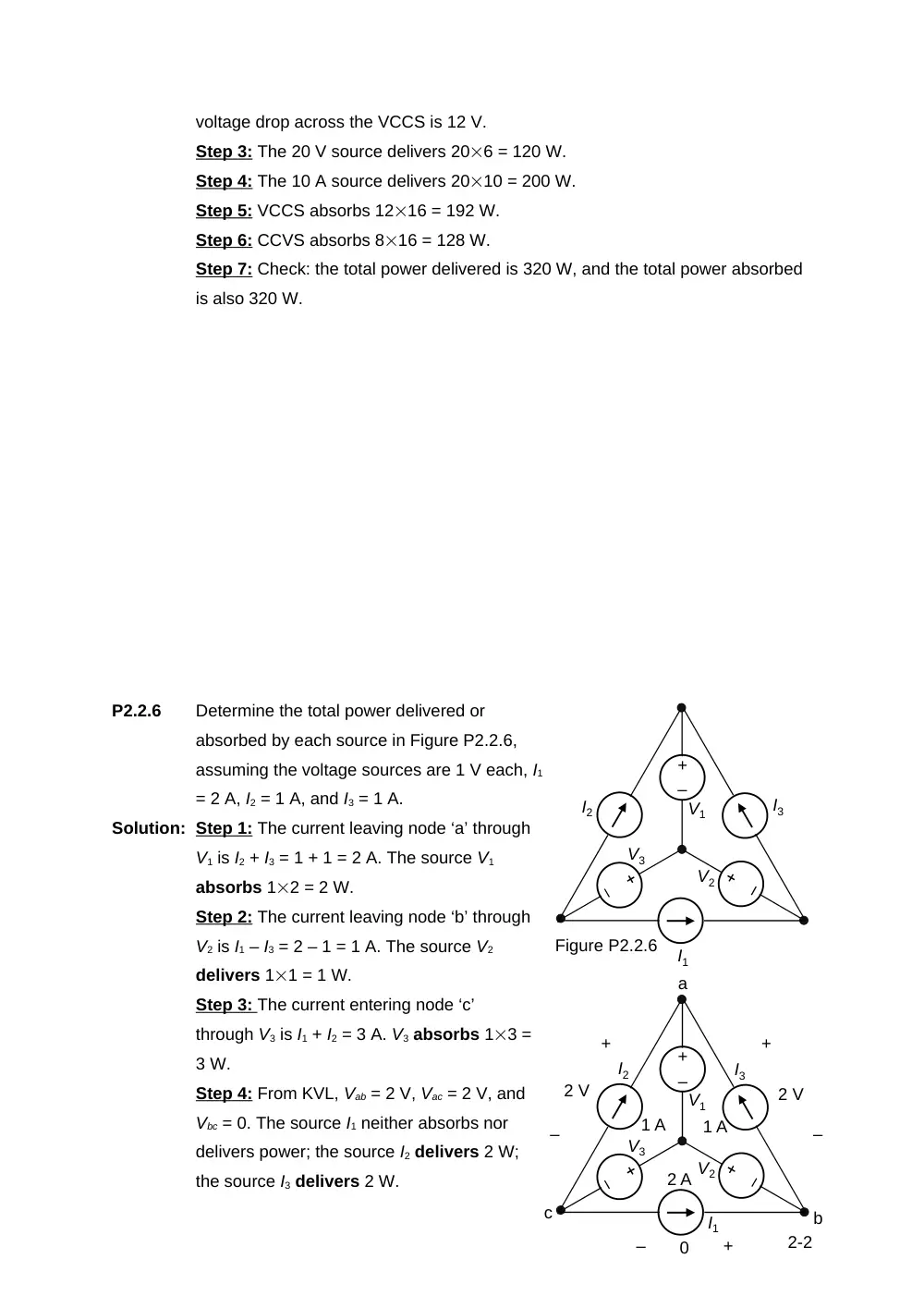
Determine in Figure P2.2.5 the
voltage across each current
source, the current through each
voltage source, and the power
delivered or absorbed by each
source.
Solution: Vab = 20 V, IX = 0.8Vab = 16 A. Step
1: Current leaving node ‘a’ through
dependent source is 16 A; current
entering node ‘a’ from 10 A source
is 10 A. From KCL, 6A must enter
node ‘a’ from the 20 V source.
Step 2: Voltage drop across the
CCVS = 0.5IX = 8 V; From KVL, the
1-2
Figure P2.1.5
1
3
5
t , min
v , V
10
10
Figure P2.2.5
–
+
–
+
10 A
0.8Vab
IX
20 V
a
b
0.5IX
–
+
–
+
10 A
0.8Vab
20 V
a
b
0.5IX
10 A
6 A
IX
16 A
–
+
–
+
12 V
8 V
voltage drop across the VCCS is 12 V.
Step 3: The 20 V source delivers 206 = 120 W.
Step 4: The 10 A source delivers 2010 = 200 W.
Step 5: VCCS absorbs 1216 = 192 W.
Step 6: CCVS absorbs 816 = 128 W.
Step 7: Check: the total power delivered is 320 W, and the total power absorbed
is also 320 W.
P2.2.6
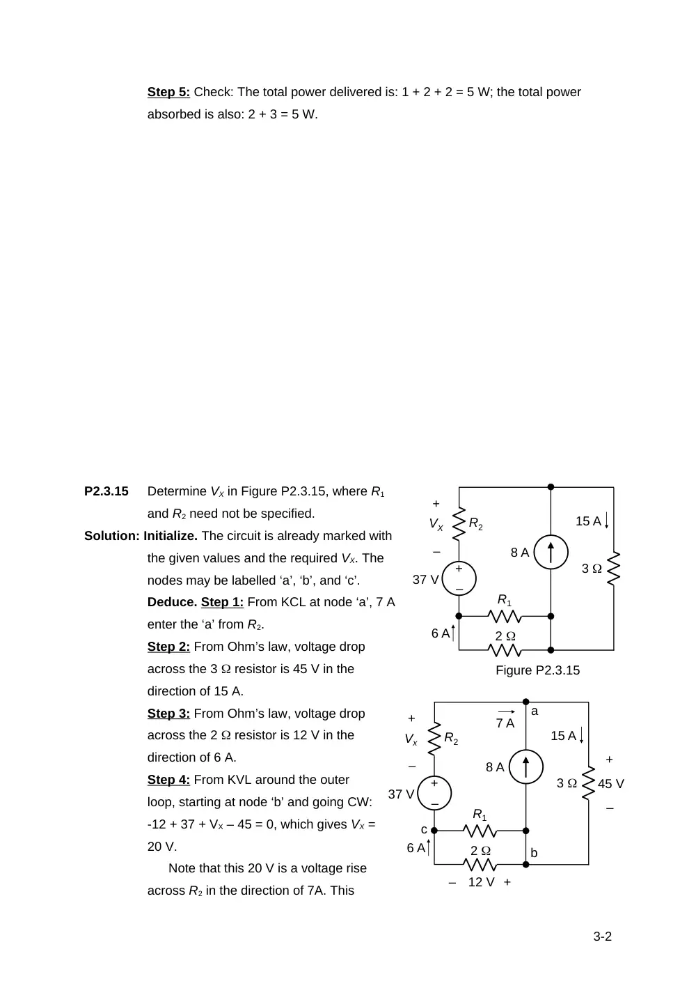
Determine the total power delivered or
absorbed by each source in Figure P2.2.6,
assuming the voltage sources are 1 V each, I1
= 2 A, I2 = 1 A, and I3 = 1 A.
Solution: Step 1: The current leaving node ‘a’ through
V1 is I2 + I3 = 1 + 1 = 2 A. The source V1
absorbs 12 = 2 W.
Step 2: The current leaving node ‘b’ through
V2 is I1 – I3 = 2 – 1 = 1 A. The source V2
delivers 11 = 1 W.
Step 3: The current entering node ‘c’
through V3 is I1 + I2 = 3 A. V3 absorbs 13 =
3 W.
Step 4: From KVL, Vab = 2 V, Vac = 2 V, and
Vbc = 0. The source I1 neither absorbs nor
delivers power; the source I2 delivers 2 W;
the source I3 delivers 2 W.
2-2
–
+
2 A
1 A
V1
V2
V3
a
b
c
1 A
–
+
2 V
–
+
2 V
+
–
0
I1
I2
I3
–
+
I1
I2
I3
V1
V2
V3
Figure P2.2.6
Step 5: Check: The total power delivered is: 1 + 2 + 2 = 5 W; the total power
absorbed is also: 2 + 3 = 5 W.
P2.3.15
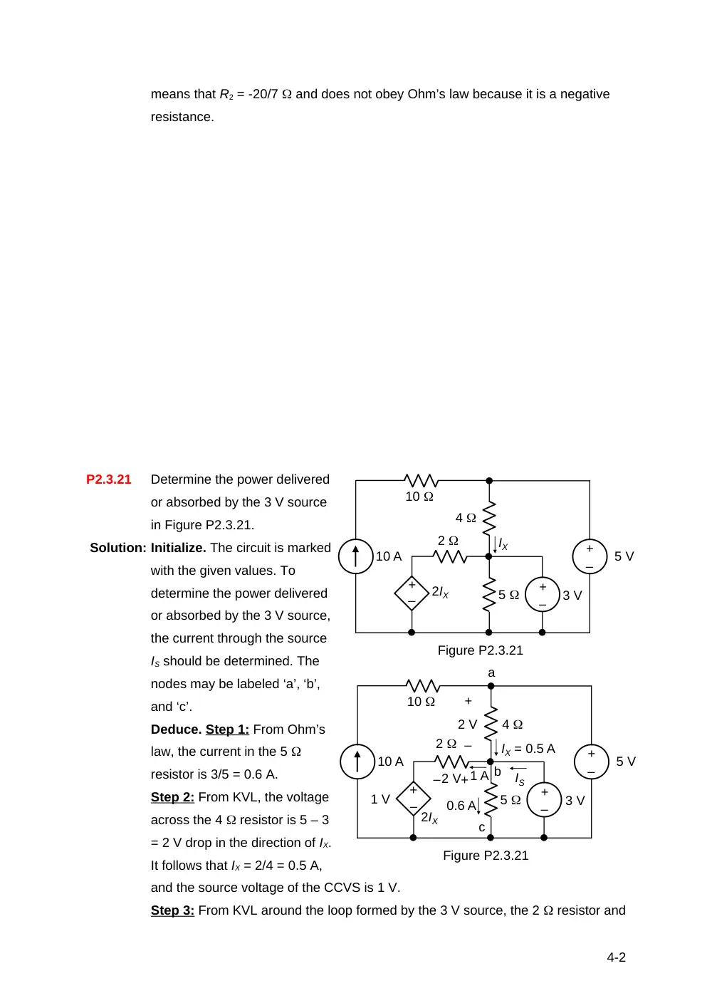
Determine VX in Figure P2.3.15, where R1
and R2 need not be specified.
Solution: Initialize. The circuit is already marked with
the given values and the required VX. The
nodes may be labelled ‘a’, ‘b’, and ‘c’.
Deduce. Step 1: From KCL at node ‘a’, 7 A
enter the ‘a’ from R2.
Step 2: From Ohm’s law, voltage drop
across the 3 resistor is 45 V in the
direction of 15 A.
Step 3: From Ohm’s law, voltage drop
across the 2 resistor is 12 V in the
direction of 6 A.
Step 4: From KVL around the outer
loop, starting at node ‘b’ and going CW:
-12 + 37 + VX – 45 = 0, which gives VX =
20 V.
Note that this 20 V is a voltage rise
across R2 in the direction of 7A. This
3-2
–
+
37 V
R2
R1
2
–
+
8 A
3
VX
15 A
6 A
Figure P2.3.15
–
+
37 V
R2
R1
2
–
+
8 A
3
Vx
15 A
6 A
7 A
a
–
+
45 V
–
+
12 V
b
c
means that R2 = -20/7 and does not obey Ohm’s law because it is a negative
resistance.
P2.3.21
Determine the power delivered
or absorbed by the 3 V source
in Figure P2.3.21.
Solution: Initialize. The circuit is marked
with the given values. To
determine the power delivered
or absorbed by the 3 V source,
the current through the source
IS should be determined. The
nodes may be labeled ‘a’, ‘b’,
and ‘c’.
Deduce. Step 1: From Ohm’s
law, the current in the 5
resistor is 3/5 = 0.6 A.
Step 2: From KVL, the voltage
across the 4 resistor is 5 – 3
= 2 V drop in the direction of IX.
It follows that IX = 2/4 = 0.5 A,
and the source voltage of the CCVS is 1 V.
Step 3: From KVL around the loop formed by the 3 V source, the 2 resistor and
4-2
10 A
2
4
10
5
–
+
5 V
–
+
–
+
3 V
IX
2IX
Figure P2.3.21
10 A
2
4
10
5
–
+
5 V
–
+
–
+
3 V
IX = 0.5 A
1 V
Figure P2.3.21
a
b
c
0.6 A
IS
1 A
–
+
2 V
2IX
–2 V+
the 2IX source, the voltage across the 2 resistor is 2 V, of the polarity shown.
From Ohm’s law, the current through this resistor is 1 A in the direction of a
voltage drop.
Step 4: From KCL at node ‘b’, 1 + 0.6 = 0.5 + IS, so that IS = 1.1 A. It follows that
the 3 V source delivers 31.1 = 3.3 W.
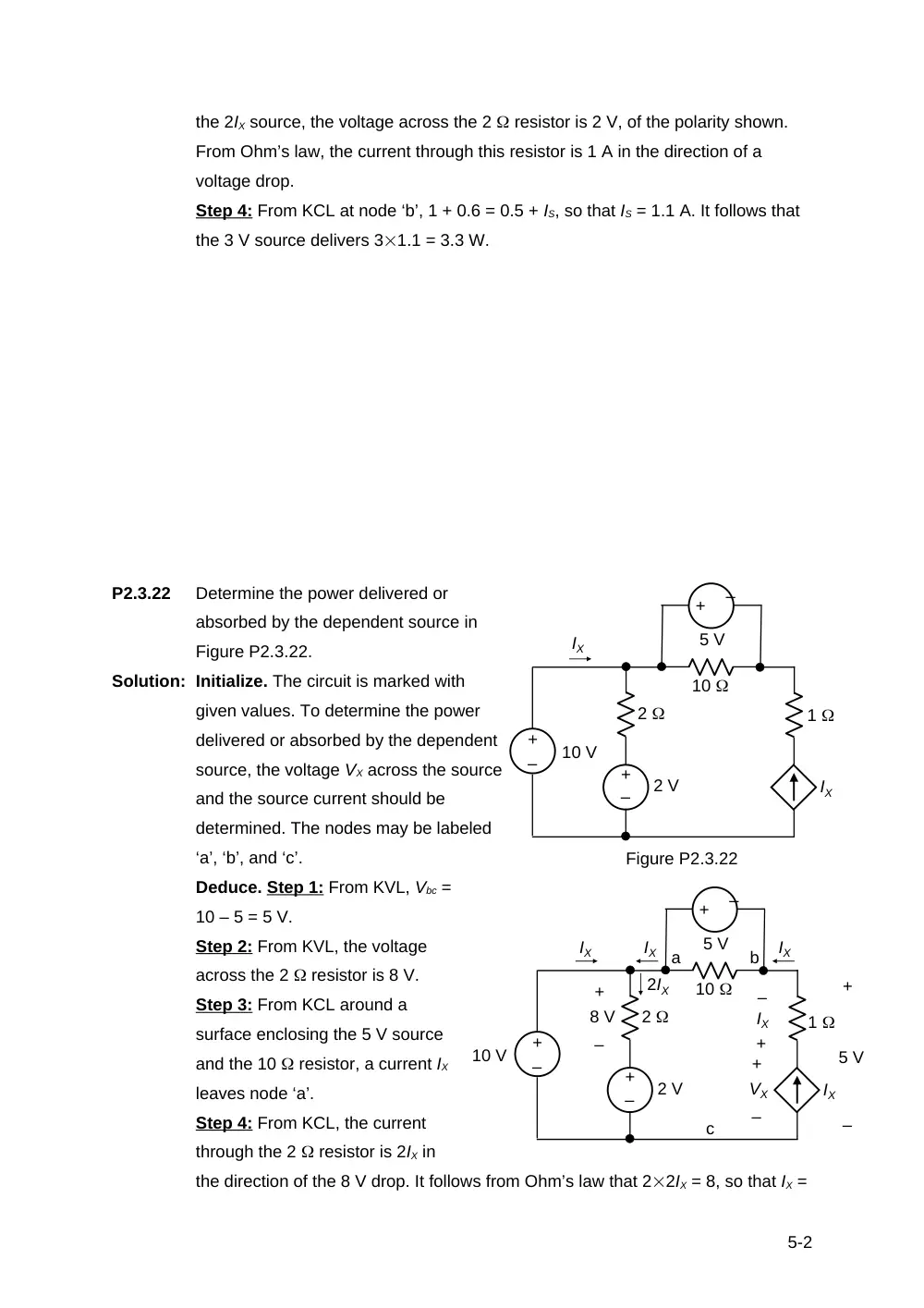
P2.3.22
Determine the power delivered or
absorbed by the dependent source in
Figure P2.3.22.
Solution: Initialize. The circuit is marked with
given values. To determine the power
delivered or absorbed by the dependent
source, the voltage VX across the source
and the source current should be
determined. The nodes may be labeled
‘a’, ‘b’, and ‘c’.
Deduce. Step 1: From KVL, Vbc =
10 – 5 = 5 V.
Step 2: From KVL, the voltage
across the 2 resistor is 8 V.
Step 3: From KCL around a
surface enclosing the 5 V source
and the 10 resistor, a current IX
leaves node ‘a’.
Step 4: From KCL, the current
through the 2 resistor is 2IX in
the direction of the 8 V drop. It follows from Ohm’s law that 22IX = 8, so that IX =
5-2
–
+
10
1
2 V
IX
IX
–
+
–
+
10 V
5 V
2
Figure P2.3.22
–
+
10
1
2 V
IX
IX
–
+
–
+
10 V
5 V
2
IX
IX
–
+
VX
a
b
2IX
–
+
8 V
–
+
5 V
IX
+
–
c
2 A.
Step 5: From KVL, Vbc = 5 = VX – IX1. Substituting IX = 2 A gives VX = 7 V. It
follows that the dependent source delivers 72 = 14 W.
P2.3.29
Determine the power delivered or
absorbed by the dependent source in
Figure P2.3.29.
Solution: Initialize. The circuit is marked with
given values. To determine the power
delivered or absorbed by the
dependent source, the voltage VX
should be determined.
Deduce. Step 1: From KCL around a
surface enclosing the dependent
source and the two batteries, the
current through the lower 10
resistor is 100 mA in the direction
shown.
Step 2: From Ohm’s law, VX = 100.1 = 1 V, so that the source current of the
dependent source is 2 A. Since the voltage across the source is 15 V, and the 2
A is in the direction of a 15 V drop across the source, the source absorbs 152 =
30 W.
6-2
+
–
+
–
10 V
5 V
2Vx
+
–
10 V
10
ISRC
10
+
– Vx
VX
2VX
Figure P2.3.29
100 mA
100 mA
+
–
10 V
10
10
+
– VX
2VX
100 mA
+
–+
–
10 V
5 V