
EECE 210 Homework 2, Fall 2015
American University of Beirut · Electric Circuits · 8 pages · Prof. Nassir Sabah


More EECE 210 files
Show the text of this homework
1-2
Homework 2
P2.1.4
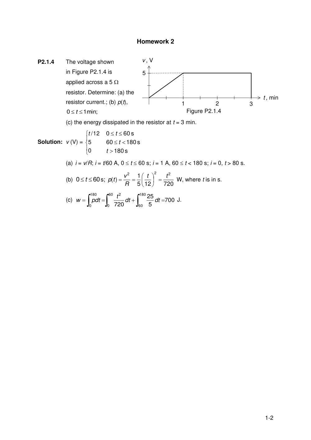
The voltage shown
in Figure P2.1.4 is
applied across a 5
resistor. Determine: (a) the
resistor current.; (b) p(t),
1min;
0
t
(c) the energy dissipated in the resistor at t = 3 min.
Solution: v (V) =
0
5
12
/t
s
180
180 s
60
60 s
0
t
t
t
(a) i = v/R; i = t/60 A, 0 t 60 s; i = 1 A, 60 t < 180 s; i = 0, t > 80 s.
(b)
60
0
t
s;
720
5 12
1
)
(
2
2
2
t
t
R
v
p t
W, where t is in s.
(c)
60
0
180
60
2
180
0
700
5
25
720
dt
dt
t
pdt
w
J.
1
3
t , min
v , V
5
2
Figure P2.1.4
2-2
P2.1.5
A voltage
t
v t
10 cos100
( )
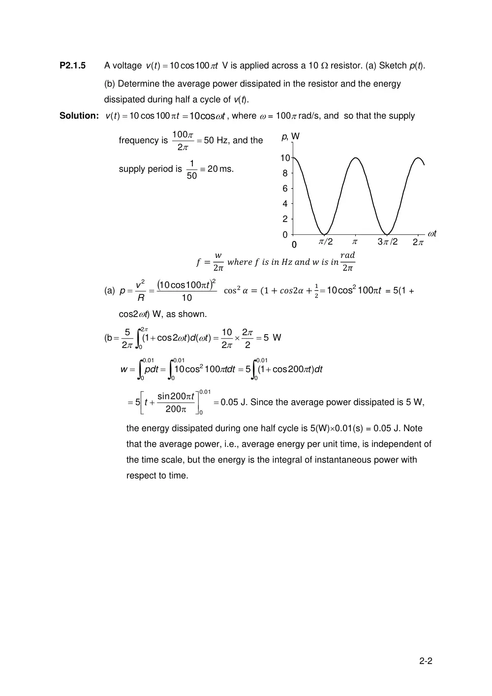
V is applied across a 10 resistor. (a) Sketch p(t).
(b) Determine the average power dissipated in the resistor and the energy
dissipated during half a cycle of v(t).
Solution:
t
v t
10 cos100
( )
10cost
, where = 100 rad/s, and so that the supply
frequency is
2
100
50 Hz, and the
supply period is
20
50
1
ms.
𝑓 = 𝑤
2𝜋 𝑤ℎ𝑒𝑟𝑒 𝑓 𝑖𝑠 𝑖𝑛 𝐻𝑧 𝑎𝑛𝑑 𝑤 𝑖𝑠 𝑖𝑛 𝑟𝑎𝑑
2𝜋
(a)
10
10cos100
2
2
t
R
v
p
cos2 𝛼 = (1 + 𝑐𝑜𝑠2𝛼 +
1
2
t
10cos 100
2
= 5(1 +
cos2t) W, as shown.
(b
5
2
2
2
10
)
) (
(1 cos2
2
5
2
0
t
t d
W
.01
0
0
2
.01
0
0
10cos 100
tdt
pdt
w
.01
0
0
)
5 (1 cos200
t dt
.01
0
0
200
sin200
5
t
t
0.05 J. Since the average power dissipated is 5 W,
the energy dissipated during one half cycle is 5(W)0.01(s) = 0.05 J. Note
that the average power, i.e., average energy per unit time, is independent of
the time scale, but the energy is the integral of instantaneous power with
respect to time.
0
2
4
6
8
10
0
p, W
/2
0
3 /2
2
t
3-2
P2.2.6
Determine in Figure P2.2.6 the voltage
across each current source, the current
through each voltage source, and the
power delivered or absorbed by
each source.
Solution: Vab = 20 V, IX = 0.8Vab = 16 A. From KCL at
node ‘a’, net current flowing away from this
node is 16 – 10 = 6 A. Hence, 6A must flow
into node ‘a’ from the 20 V source.
Voltage drop across the CCVS = 0.5Ix = 8 V;
let the voltage drop across the VCCS be VX.
From KVL the voltage drop Vab is the same
whether going through the 20 V source or
the two dependent sources. Hence
20 = VX + 8, which gives VX = 12 V.
The 20 V source delivers 206 = 120 W;
the 10 A source delivers 2010 = 200 W;
VCCS absorbs 1216 = 192 W; and CCVS
absorbs 816 = 128 W. Total power delivered = 320 W = total power absorbed.
Figure P2.2.6
–
+
10 A
0.8Vab
IX
20 V
a
b
0.5IX
+
–
10 A
6 A
16 A
–
+
–
+
12 V
8 V
Figure P2.2.6-1
–
+
10 A
0.8Vab
IX
20 V
a
b
0.5IX
+
–
4-2
P2.2.7
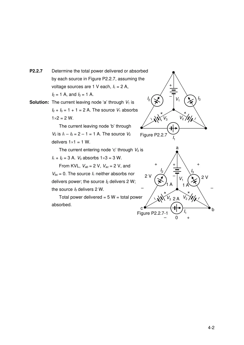
Determine the total power delivered or absorbed
by each source in Figure P2.2.7, assuming the
voltage sources are 1 V each, I1 = 2 A,
I2 = 1 A, and I3 = 1 A.
Solution: The current leaving node ‘a’ through V1 is
I2 + I3 = 1 + 1 = 2 A. The source V1 absorbs
12 = 2 W.
The current leaving node ‘b’ through
V2 is I1 – I3 = 2 – 1 = 1 A. The source V2
delivers 11 = 1 W.
The current entering node ‘c’ through V3 is
I1 + I2 = 3 A. V3 absorbs 13 = 3 W.
From KVL, Vab = 2 V, Vac = 2 V, and
Vbc = 0. The source I1 neither absorbs nor
delivers power; the source I2 delivers 2 W;
the source I3 delivers 2 W.
Total power delivered = 5 W = total power
absorbed.
I1
I2
I3
V1
V2
V3
Figure P2.2.7
+
–
2 A
1 A
a
b
c
1 A
–
+
2 V
–
+
2 V
+
–
0
I1
I2
I3
V1
V2
V3
Figure P2.2.7-1
+
–
5-2
P2.2.8
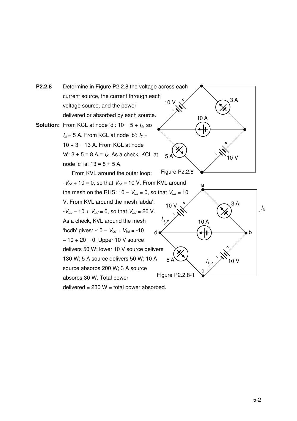
Determine in Figure P2.2.8 the voltage across each
current source, the current through each
voltage source, and the power
delivered or absorbed by each source.
Solution: From KCL at node ‘d’: 10 = 5 + I, so
I = 5 A. From KCL at node ‘b’: IY =
10 + 3 = 13 A. From KCL at node
‘a’: 3 + 5 = 8 A = IX. As a check, KCL at
node ‘c’ is: 13 = 8 + 5 A.
From KVL around the outer loop:
-Vcd + 10 = 0, so that Vcd = 10 V. From KVL around
the mesh on the RHS: 10 – Vba = 0, so that Vba = 10
V. From KVL around the mesh ‘abda’:
-Vba – 10 + Vbd = 0, so that Vbd = 20 V.
As a check, KVL around the mesh
‘bcdb’ gives: -10 – Vcd + Vbd = -10
– 10 + 20 = 0. Upper 10 V source
delivers 50 W; lower 10 V source delivers
130 W; 5 A source delivers 50 W; 10 A
source absorbs 200 W; 3 A source
absorbs 30 W. Total power
delivered = 230 W = total power absorbed.
Figure P2.2.8
3 A
10 A
5 A
10 V
10 V
a
b
c
d
I
IX
IY
Figure P2.2.8-1
3 A
10 A
5 A
10 V
10 V
6-2
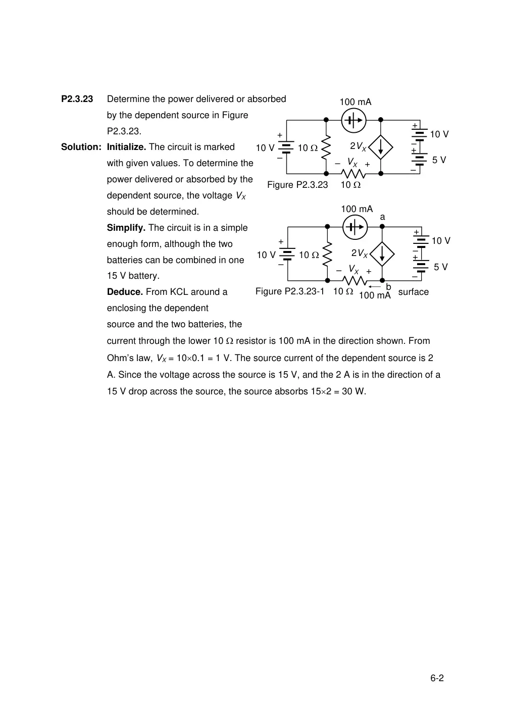
P2.3.23
Determine the power delivered or absorbed
by the dependent source in Figure
P2.3.23.
Solution: Initialize. The circuit is marked
with given values. To determine the
power delivered or absorbed by the
dependent source, the voltage VX
should be determined.
Simplify. The circuit is in a simple
enough form, although the two
batteries can be combined in one
15 V battery.
Deduce. From KCL around a
surface
enclosing the dependent
source and the two batteries, the
current through the lower 10 resistor is 100 mA in the direction shown. From
Ohm’s law, VX = 100.1 = 1 V. The source current of the dependent source is 2
A. Since the voltage across the source is 15 V, and the 2 A is in the direction of a
15 V drop across the source, the source absorbs 152 = 30 W.
Figure P2.3.23
100 mA
+
–
+
–+
–
10 V
5 V
10 V
10
10
+
– VX
2VX
100 mA
+
–
10 V
10
10
+
– VX
2VX
100 mA
a
Figure P2.3.23-1
b
+
–+
–
10 V
5 V
7-2
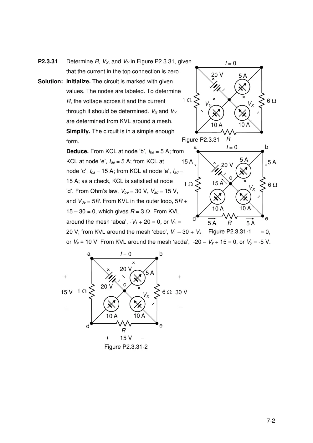
P2.3.31
Determine R, VX, and VY in Figure P2.3.31, given
that the current in the top connection is zero.
Solution: Initialize. The circuit is marked with given
values. The nodes are labeled. To determine
R, the voltage across it and the current
through it should be determined. VX and VY
are determined from KVL around a mesh.
Simplify. The circuit is in a simple enough
form.
Deduce. From KCL at node ‘b’, Ibe = 5 A; from
KCL at node ‘e’, Ide = 5 A; from KCL at
node ‘c’, Ica = 15 A; from KCL at node ‘a’, Iad =
15 A; as a check, KCL is satisfied at node
‘d’. From Ohm’s law, Vbe = 30 V, Vad = 15 V,
and Vde = 5R. From KVL in the outer loop, 5R +
15 – 30 = 0, which gives R = 3 . From KVL
around the mesh ‘abca’, -V1 + 20 = 0, or V1 =
20 V; from KVL around the mesh ‘cbec’, V1 – 30 + Vx
= 0,
or Vx = 10 V. From KVL around the mesh ‘acda’, -20 – Vy + 15 = 0, or Vy = -5 V.
a
b
c
d
e
5 A
5 A
15 A
15 A
5 A
Figure P2.3.31-1
5 A
10 A
10 A
6
1
VX
20 V
I = 0
R
5 A
10 A
10 A
6
1
VX
VY
20 V
I = 0
Figure P2.3.31
R
15 V
+
–
+
–
15 V
Figure P2.3.31-2
a
b
c
d
e
5 A
10 A
10 A
6
1
VX
20 V
I = 0
R
30 V
+
–
20 V
8-2
P2.3.32
Determine IO in Figure P2.3.32.
Solution: Initialize. The circuit is marked with
given values. The nodes are labeled.
Simplify. The circuit is in a simple
enough form.
Deduce. Vab = 2IO, so that the current in
the 2 resistor is IO. From KCL at node ‘a’,
Ida = 3IO. From KCL at node ‘b’, Ibc = 0. From
KVL around the mesh ‘abcd’, -2IO + 0 + 5 – 3IO
= 0, which gives IO = 1 A.
IO
2
1
1
1
1
IO
2IO
Figure P2.3.32
+
–
5 V
IO
2
1
1
1
1
IO
2IO
IO
IO
3IO
I = 0
Figure P2.3.32-1
+
–
5 V
a
b
c
d