
EECE 210 Homework 3, Fall 2015
American University of Beirut · Electric Circuits · 5 pages · Prof. Nassir Sabah
More EECE 210 files
Show the text of this homework
1-2
Homework 3
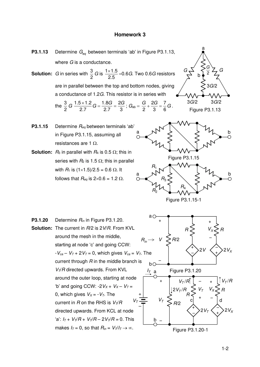
P3.1.13
Determine
Geq
between terminals ‘ab’ in Figure P3.1.13,
where G is a conductance.
Solution: G in series with 2
3 G is
.5
2
11.5
0.6G. Two 0.6G resistors
are in parallel between the top and bottom nodes, giving
a conductance of 1.2G. This resistor is in series with
the 2
3 G
3
2
2.7
.8
1
.7
2
1.2
1.5
G
G
G
; Gab
G
G
G
6
7
3
2
2
.
P3.1.15
Determine Req between terminals ‘ab’
in Figure P3.1.15, assuming all
resistances are 1 .
Solution: R3 in parallel with R4 is 0.5 ; this in
series with R2 is 1.5 ; this in parallel
with R1 is (11.5)/2.5 = 0.6 . It
follows that Req is 20.6 = 1.2 .
P3.1.20
Determine Rin in Figure P3.1.20.
Solution: The current in R/2 is 2V/R. From KVL
around the mesh in the middle,
starting at node ‘c’ and going CCW:
-Vca – VT + 2VT = 0, which gives Vca = VT. The
current through R in the middle branch is
VT/R directed upwards. From KVL
around the outer loop, starting at node
‘b’ and going CCW: -2VX + VX – VT =
0, which gives VX = -VT. The
current in R on the RHS is VT/R
directed upwards. From KCL at node
‘a’: IT + VT/R + VT/R – 2VT/R = 0. This
makes IT = 0, so that Rin = VT/IT .
a
b
G
G
2
G
Figure P3.1.13
3G/2
3G/2
3G/2
a
b
Figure P3.1.15
a
b
Figure P3.1.15-1
R1
R2
R3
R4
R/2
Figure P3.1.20
a
b
Rin
+
–
R
2V
+
–
+
–
V
VX
R
2VX
–
+
R/2
Figure P3.1.20-1
a
b
+
–
R
2VT
+
–
+
–
VT
VX
R
2VX
–
+
IT
2VT /R
+
–
VT
VT /R
VT /R
c
d
+
–
VT
2-2
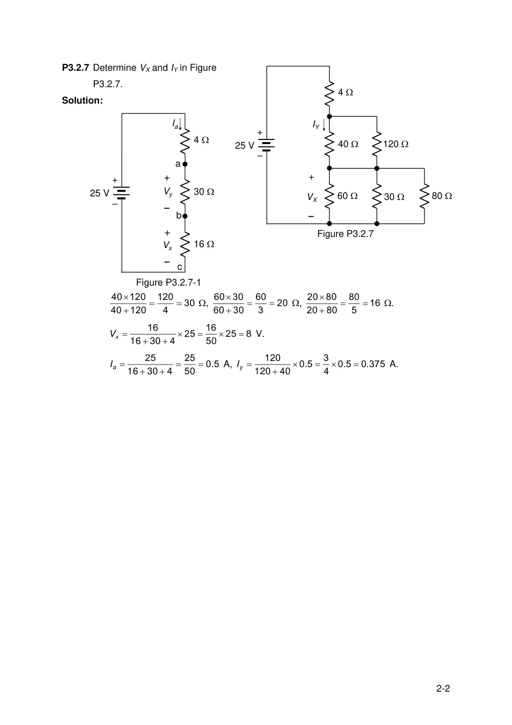
P3.2.7 Determine VX and IY in Figure
P3.2.7.
Solution:
30
4
120
120
40
40 120
,
20
3
60
30
60
30
60
,
16
5
80
80
20
80
20
.
8
25
50
16
25
4
16
30
16
Vx
V.
0 5
50
25
4
25
.
30
16
aI
A,
0 375
0 5
4
3
0 5
40
120
.
.
.
120
yI
A.
4
40
60
120
30
80
25 V
IY
+
–
VX
Figure P3.2.7
+
–
4
30
16
Vx
Vy
–
+
–
+
Ia
a
b
c
25 V
+
–
Figure P3.2.7-1
3-2
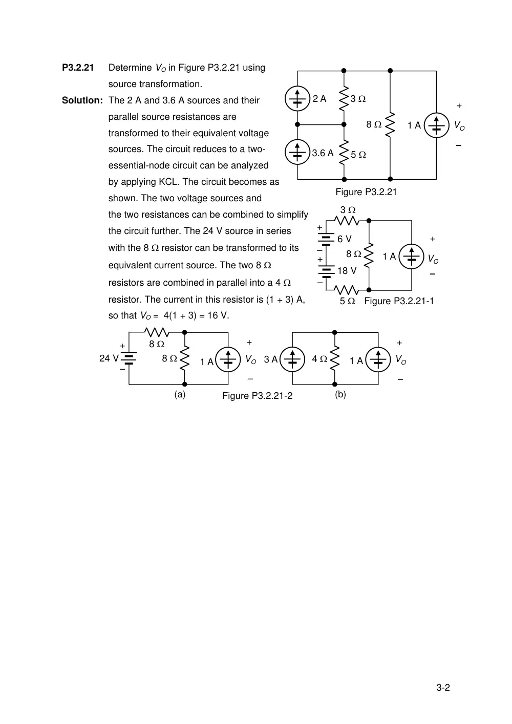
P3.2.21
Determine VO in Figure P3.2.21 using
source transformation.
Solution: The 2 A and 3.6 A sources and their
parallel source resistances are
transformed to their equivalent voltage
sources. The circuit reduces to a two-
essential-node circuit can be analyzed
by applying KCL. The circuit becomes as
shown. The two voltage sources and
the two resistances can be combined to simplify
the circuit further. The 24 V source in series
with the 8 resistor can be transformed to its
equivalent current source. The two 8
resistors are combined in parallel into a 4
resistor. The current in this resistor is (1 + 3) A,
so that VO = 4(1 + 3) = 16 V.
2 A
3.6 A
3
5
8
1 A
Figure P3.2.21
+
–
VO
18 V
+
–
+
–
6 V
1 A
+
–
VO
3
8
5
Figure P3.2.21-1
8
24 V
Figure P3.2.21-2
–
+
+
–
8
1 A
VO
–
+
4
1 A
VO
3 A
(a)
(b)
4-2
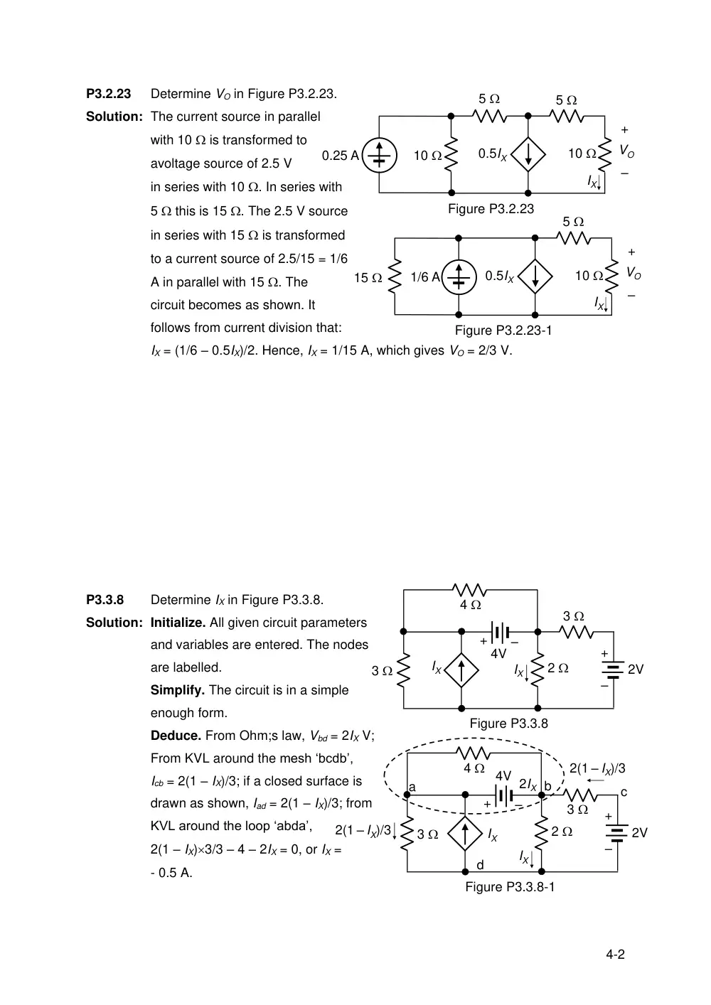
P3.2.23
Determine VO in Figure P3.2.23.
Solution: The current source in parallel
with 10 is transformed to
avoltage source of 2.5 V
in series with 10 . In series with
5 this is 15 . The 2.5 V source
in series with 15 is transformed
to a current source of 2.5/15 = 1/6
A in parallel with 15 . The
circuit becomes as shown. It
follows from current division that:
IX = (1/6 – 0.5IX)/2. Hence, IX = 1/15 A, which gives VO = 2/3 V.
P3.3.8
Determine IX in Figure P3.3.8.
Solution: Initialize. All given circuit parameters
and variables are entered. The nodes
are labelled.
Simplify. The circuit is in a simple
enough form.
Deduce. From Ohm;s law, Vbd = 2IX V;
From KVL around the mesh ‘bcdb’,
Icb = 2(1 – IX)/3; if a closed surface is
drawn as shown, Iad = 2(1 – IX)/3; from
KVL around the loop ‘abda’,
2(1 – IX)3/3 – 4 – 2IX = 0, or IX =
- 0.5 A.
15
0.5IX
IX
5
10
1/6 A
Figure P3.2.23-1
+
–
VO
5
10
0.5IX
IX
5
10
0.25 A
Figure P3.2.23
+
–
VO
IX
3
+
–
+
–
4
3
2
2V
4V
IX
Figure P3.3.8
IX
3
+
–
+
–
4
3
2
2V
4V 2IX
IX
a
b
d
2(1 – IX)/3
2(1 – IX)/3
Figure P3.3.8-1
c
5-2
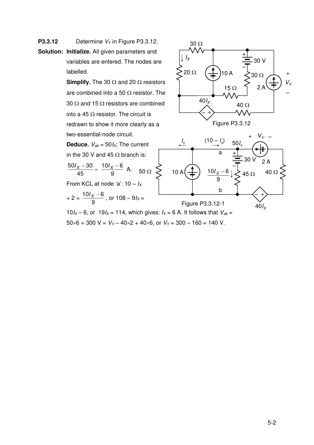
P3.3.12
Determine VY in Figure P3.3.12.
Solution: Initialize. All given parameters and
variables are entered. The nodes are
labelled.
Simplify. The 30 and 20 resistors
are combined into a 50 resistor. The
30 and 15 resistors are combined
into a 45 resistor. The circuit is
redrawn to show it more clearly as a
two-essential-node circuit.
Deduce. Vab = 50IX; The current
in the 30 V and 45 branch is:
45
30
50 X
I
9
6
10
IX
A.
From KCL at node ‘a’: 10 – IX
+ 2 =
9
6
10
IX
, or 108 – 9IX =
10IX – 6, or 19IX = 114, which gives: IX = 6 A. It follows that Vab =
506 = 300 V = VY – 402 + 406, or VY = 300 – 160 = 140 V.
+
–
10 A
30
30
20
15
30 V
–
+
Ix
40Ix
40
2 A
+
–
VY
Figure P3.3.12
IX
40IX
+
–
10 A
45
50
30 V
Ix
2 A
+
–
VY
40IX
40
–
+
(10 – Ix)
50Ix
a
b
9
6
10
X
I
Figure P3.3.12-1