
EECE 210 Homework 3 with Solution, Fall 2013
American University of Beirut · Electric Circuits · 6 pages · with solution


More EECE 210 files
Show the text of this homework
Homework 3
P3.1.2
Determine Req in
Figure P3.1.2.
Solution: On the RHS, (0.5
k||2 k) = 1/2.5 = 0.4 k; in series with 0.1 k, this becomes 0.5 k; in parallel
with 2 k, this gives again 0.4 k. On the LHS, (0.6 k||1.2 k) = 0.72/1.8 = 0.4
k; in series with 0.2 k, this becomes 0.6 k; in parallel with 0.3 k, this gives
0.18/0.9 = 0.2 k. This resistance appears in series with the0.4 k from the
RHS, giving a total of 0.6 k. Req = (1.8 k||0.6 k) = 0.45 k.
P3.1.9
Determine between terminals ab in Figure P3.1.9.
Solution: G in series with G is 0.6 G. The G resistor
connected to node b may be split into two G
resistors, each of which is in series with 0.6 G. This gives ;
Gab .
P3.1.14
Determine each of the
resistors of the equivalent delta
between terminals ‘a’, ‘b’, and
‘c in Figure P3.1.14, expressed
in S.
Solution: The inner is transformed to
three 2/3 resistors
1-3
a
b
G
G
2
G
Figure P3.1.9
3G/2
3G/2
3G/2
2
3 S
3 S
1/6 S
a
1/6 S
0.5 k
0.1 k
2 k
1.2 k
2 k
0.3 k
0.2 k
0.6 k
1.8 k
Req
a
b
Figure P3.1.2
connected in Y. To each is added 1/3 in series to give three 1 resistors
connected in Y. These are transformed to three 1/3 S resistors connected in .
Each of the resistors of the equivalent will be (1/3 + 1/6) = 1/2 S.
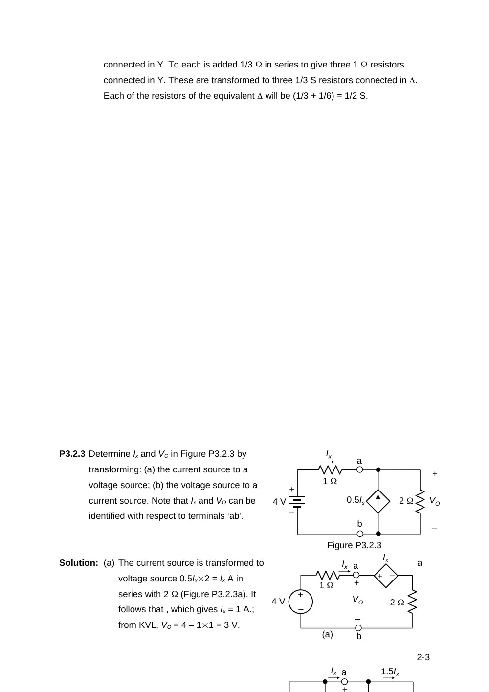
P3.2.3 Determine Ix and VO in Figure P3.2.3 by
transforming: (a) the current source to a
voltage source; (b) the voltage source to a
current source. Note that Ix and VO can be
identified with respect to terminals ‘ab’.
Solution: (a) The current source is transformed to
a
voltage source 0.5Ix2 = Ix A in
series with 2 (Figure P3.2.3a). It
follows that , which gives Ix = 1 A.;
from KVL, VO = 4 – 11 = 3 V.
2-3
–
+
Ix
Ix
2
1
4 V
–
+
VO
a
b
+ –
(a)
Ix
+
a
1.5Ix
Ix
0.5Ix
2
1
4 V
Figure P3.2.3
–
+
VO
a
b
+
–
(b) The voltage source is transformed to a current source 4/1 = 4 V in parallel
with 1 (Figure P3.2.3b). The two current sources are combined to (4 +
0.5Ix) and the two resistances to (1||2) = 2/3 . Hence, , with VO = 21.5Ix. =
3Ix. This gives Ix = 1 A and VO = 3 V, as before.
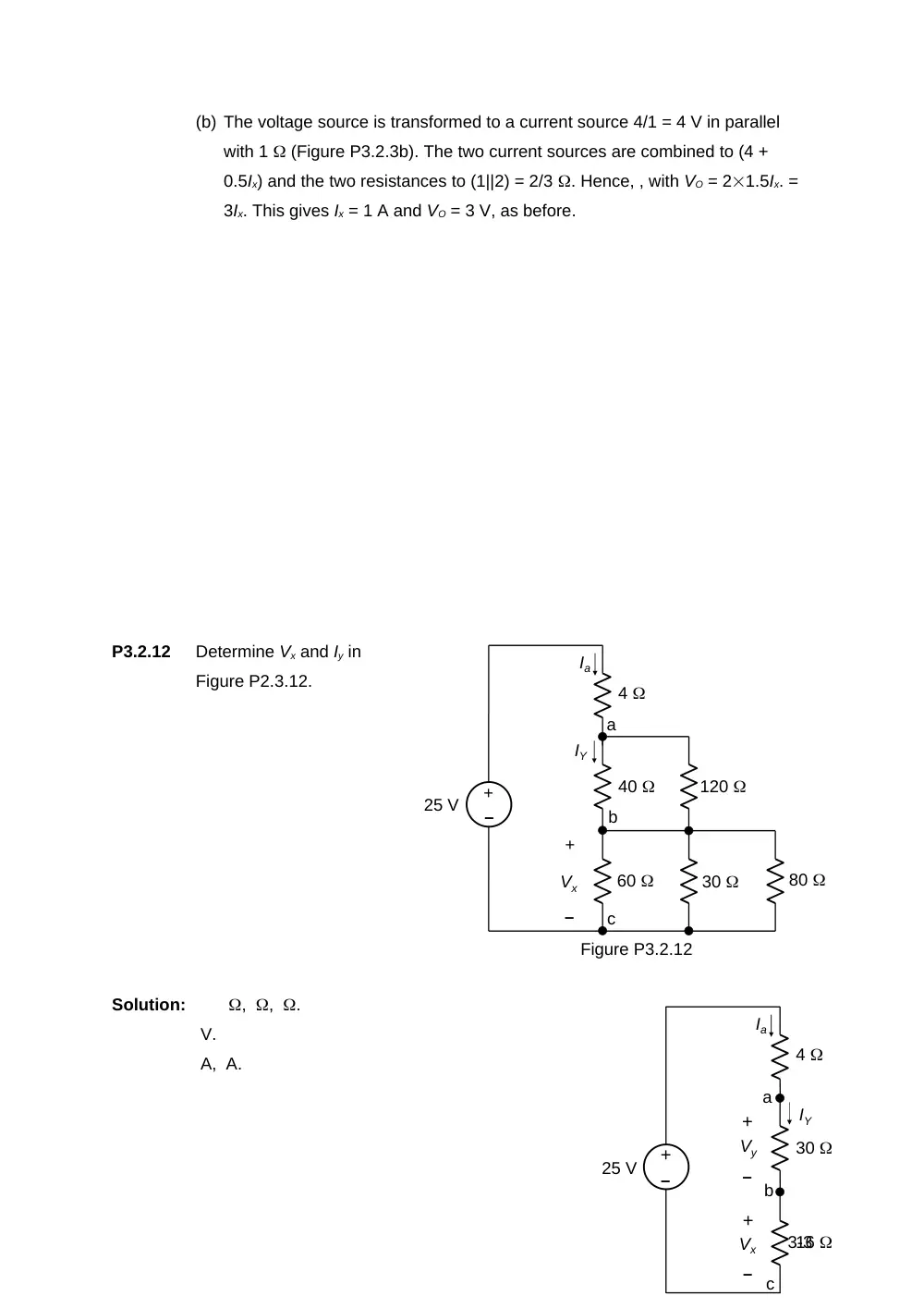
P3.2.12
Determine Vx and Iy in
Figure P2.3.12.
Solution:
, , .
V.
A, A.
3-3
4
40
60
120
30
80
–
+
25 V
IY
+
–
Vx
Figure P3.2.12
a
b
c
Ia
4
30
16
25 V
IY
Vx
Vy
–
+
–
+
–
+
Ia
a
b
c
P3.2.15
Determine IO in Figure P3.2.15
using source transformations.
Solution: The voltage of node ‘a’
with respect to the lower
reference node is 3Ix V,
and the voltage of node ‘b’
is (3Ix – 2IO) V. The 10 V
source in series with 2 is
transformed to a 5 A source in parallel with 2 . This resistance is combined with
the 3 resistance to give a resistance of 23/5 = 1.2 . The current in this
resistance is 3Ix/1.2 = 2.5 Ix. The 3Ix dependent source in series with 5 is
transformed to a 0.6 A source in parallel with 2 . This resistance is combined
with the 5 resistance to give a resistance of 25/7 = 10/7 . The current in this
resistance is 7(3Ix – 2IO)/10 = 2.1Ix – 1.4IO.
KCL at node ‘a’ gives, 2.5Ix + IO + 5 = 0, or Ix = -2 – 0.4IO. KCL at node ‘b’
gives: IO + 0.6Ix = 2.1Ix – 1.4IO, or 2.4IO = 1.5Ix, or Ix = 1.6IO. Substituting the first
equation, 1.6IO = -2 – 0.4IO, gives IO = -1 A.
4-3
+
–
10 V
2
2
3
2
–
+
5
3Ix
Ix
IO
Figure P3.2.15
5 A
2
1.2
10/7
0.6Ix
2.5Ix
IO
3Ix V
(3Ix – 2IO) V
2.1Ix – 1.4IO
a
b
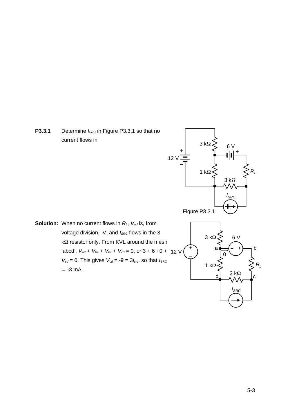
P3.3.1
Determine ISRC in Figure P3.3.1 so that no
current flows in
Solution: When no current flows in RL, Vad is, from
voltage division, V, and ISRC flows in the 3
k resistor only. From KVL around the mesh
‘abcd’, Vad + Vba + Vbc + Vcd = 0, or 3 + 6 +0 +
Vcd = 0. This gives Vcd = -9 = 3Isrc. so that ISRC
-3 mA.
5-3
3 k
RL
1 k
3 k
6 V
12 V
ISRC
Figure P3.3.1
+
–
+
–
–
+
–
+
3 k
RL
1 k
3 k
6 V
12 V
ISRC
a
b
c
d
0
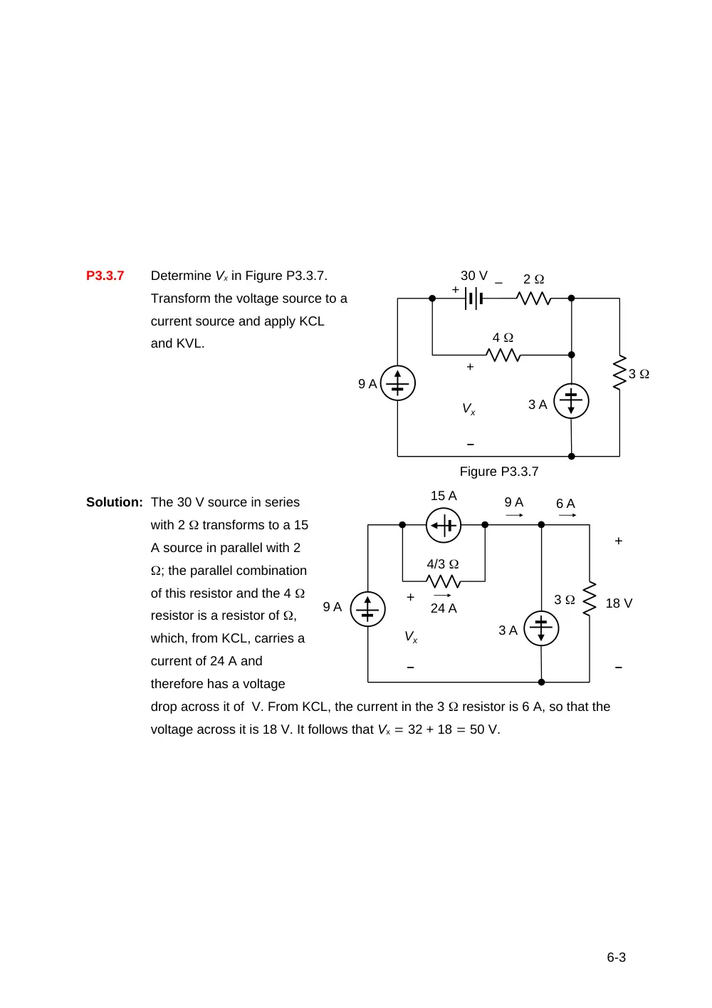
P3.3.7
Determine Vx in Figure P3.3.7.
Transform the voltage source to a
current source and apply KCL
and KVL.
Solution: The 30 V source in series
with 2 transforms to a 15
A source in parallel with 2
; the parallel combination
of this resistor and the 4
resistor is a resistor of ,
which, from KCL, carries a
current of 24 A and
therefore has a voltage
drop across it of V. From KCL, the current in the 3 resistor is 6 A, so that the
voltage across it is 18 V. It follows that Vx 32 + 18 50 V.
6-3
9 A
3 A
30 V
2
4
3
+
–
Vx
Figure P3.3.7
+
–
9 A
3 A
15 A
4/3
3
Vx
24 A
9 A
6 A
18 V
–
+
–
+