
EECE 210 Homework 3 with Solution, Fall 2014
American University of Beirut · Electric Circuits · 5 pages · with solution
More EECE 210 files
Show the text of this homework
10 k
30 mA
2 k
4 k
3 k
1.5 k
600
IO
a
b
c
Homework 3
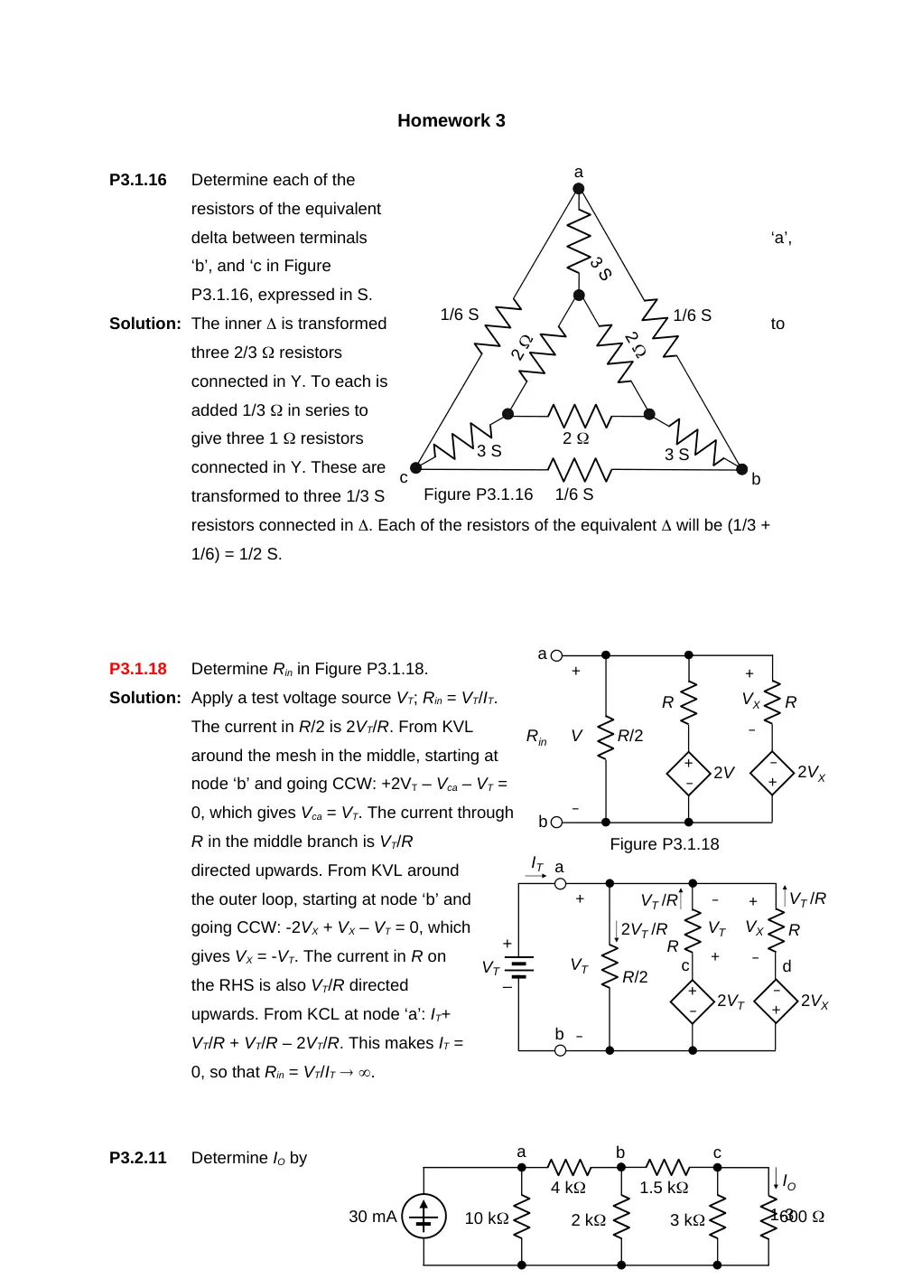
P3.1.16
Determine each of the
resistors of the equivalent
delta between terminals
‘a’,
‘b’, and ‘c in Figure
P3.1.16, expressed in S.
Solution: The inner is transformed
to
three 2/3 resistors
connected in Y. To each is
added 1/3 in series to
give three 1 resistors
connected in Y. These are
transformed to three 1/3 S
resistors connected in . Each of the resistors of the equivalent will be (1/3 +
1/6) = 1/2 S.
P3.1.18
Determine Rin in Figure P3.1.18.
Solution: Apply a test voltage source VT; Rin = VT/IT.
The current in R/2 is 2VT/R. From KVL
around the mesh in the middle, starting at
node ‘b’ and going CCW: +2VT – Vca – VT =
0, which gives Vca = VT. The current through
R in the middle branch is VT/R
directed upwards. From KVL around
the outer loop, starting at node ‘b’ and
going CCW: -2VX + VX – VT = 0, which
gives VX = -VT. The current in R on
the RHS is also VT/R directed
upwards. From KCL at node ‘a’: IT+
VT/R + VT/R – 2VT/R. This makes IT =
0, so that Rin = VT/IT .
P3.2.11
Determine IO by
1-3
2
3 S
3 S
1/6 S
a
b
c
1/6 S
1/6 S
Figure P3.1.16
R/2
Figure P3.1.18
a
b
Rin
+
–
R
2V
+
–
+
–
V
VX
R
2VX
–
+
R/2
a
b
+
–
R
2VT
+
–
+
–
VT
VX
R
2VX
–
+
IT
2VT /R
+
–
VT
VT /R
VT /R
c
d
+
–
VT
5 A
3
Ix
IO
3Ix
2
7
24
0.25IX
successive current division at nodes ‘c’, ‘b’, and then ‘a’ in Figure P3.2.11.
Solution: The resistance between nodes ‘c’ and ‘d’ is 0.6||3 = 0.5 k;
From Ohm’s law 0.5Ibc = 0.6IO so that Ibc = 1.2IO. The resistance to the right of
node ‘b’ is (1.5 + 0.5)
= 2 k. Hence, Iab =
2Ibc = 2.4IO. The
resistance to the
right of node ‘a’ is (4
+ 2||2) = 5 k, which
is one-half of 10 k.
Hence, Iab =
(2/3)30 mA = 20 mA. equating this to 2.4IO, gives IO = 20/2.4 = 200/24 = 25/3
mA.
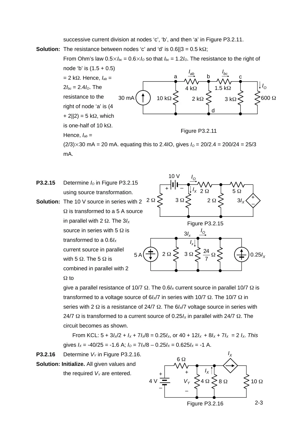
P3.2.15
Determine IO in Figure P3.2.15
using source transformation.
Solution: The 10 V source in series with 2
is transformed to a 5 A source
in parallel with 2 . The 3IX
source in series with 5 is
transformed to a 0.6IX
current source in parallel
with 5 . The 5 is
combined in parallel with 2
to
give a parallel resistance of 10/7 . The 0.6IX current source in parallel 10/7 is
transformed to a voltage source of 6IX/7 in series with 10/7 . The 10/7 in
series with 2 is a resistance of 24/7 . The 6IX/7 voltage source in series with
24/7 is transformed to a current source of 0.25IX in parallel with 24/7 . The
circuit becomes as shown.
From KCL: 5 + 3IX/2 + IX + 7IX/8 = 0.25IX, or 40 + 12IX + 8IX + 7IX = 2 IX. This
gives IX = -40/25 = -1.6 A; IO = 7IX/8 – 0.25IX = 0.625IX = -1 A.
P3.2.16
Determine VY in Figure P3.2.16.
Solution: Initialize. All given values and
the required VY are entered.
2-3
10 k
30 mA
2 k
4 k
3 k
1.5 k
600
IO
Figure P3.2.11
a
b
c
Ibc
Iab
d
+
–
10 V
2
2
3
2
–
+
5
3IX
IX
IO
Figure P3.2.15
Figure P3.2.16
VY
IXIX
+
–
VSRC
4
8
10
Ix
Ix
6
+
–
Vy
IX
IX
4 V
VY
Deduce. Step 1: From KCL the current between the 4 and 8 resistors is
zero. Step 2: This means that VY can be obtained by voltage division as: V.
P3.3.1
Determine ISRC in Figure P3.3.1
so that no current flows in
Solution: Initialize. The given values are entered, the
nodes are labelled, and zero current is
assumed to flow.
Deduce. Step 1: Because of the zero
current, the same current passes through
the 3 k and 1 k resistors. Hence, voltage
division applies, and V. Step 2: Vbc = 0,
since no current flows in RL. Step 3: From KCL at node ‘c’, ISRC flows through the
3 k resistor, so that Vcd = 3ISRC. Step4:
Applying KVL around the mesh ‘dabc’
starting at node ‘d’ and going CW: 3 + 6 + 0
– 3ISRC = 0, which gives ISRC = 3 mA.
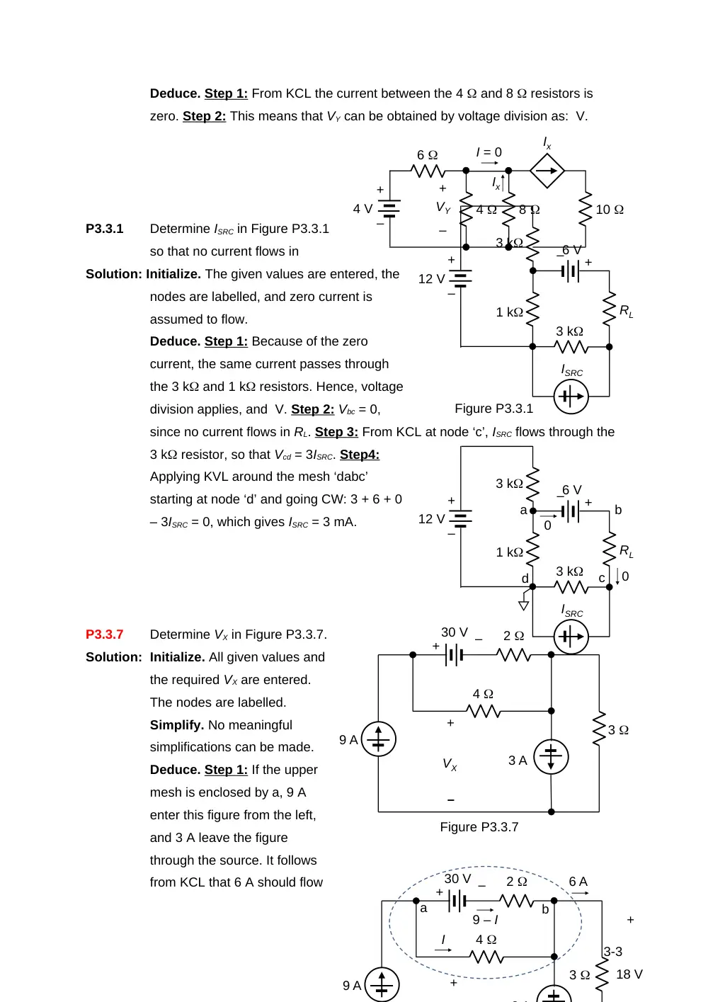
P3.3.7
Determine VX in Figure P3.3.7.
Solution: Initialize. All given values and
the required VX are entered.
The nodes are labelled.
Simplify. No meaningful
simplifications can be made.
Deduce. Step 1: If the upper
mesh is enclosed by a, 9 A
enter this figure from the left,
and 3 A leave the figure
through the source. It follows
from KCL that 6 A should flow
3-3
+
–
4
8
6
10
Ix
Ix
4 V
+
–
VY
I = 0
3 k
RL
1 k
3 k
6 V
12 V
ISRC
Figure P3.3.1
+
–
+
–
3 k
RL
1 k
3 k
6 V
12 V
ISRC
+
–
+
–
a
b
c
d
0
0
9 A
3 A
30 V
2
4
3
+
–
VX
Figure P3.3.7
+
–
9 A
3 A
30 V
2
4
3
+
+
–
6 A
+
18 V
I
9 – I
a
b
through the 3 resistor. Step 2: voltage drop across the 3 resistor is 18 V in
the direction of the 6A.
Explore. To derive VX, the voltage across the 4 resistor is needed. If an
unknown current I is assigned through this resistor, the current in the upper
branch is, from KCL at node ‘a’: (9 – I); I can then be found from KVL around the
mesh. Starting at node ‘a’ and going CW; -30 -2(9 – I) + 4I = 0. This gives I = 8 A.
It follows that VX = 48 + 18 = 50 V.
Check. The 30 V source in
series with 2 is transformed
to a 15 A source in parallel with
2 ; the parallel combination of
this resistor and the 4 resistor
is a resistor of . From KCL at
node ‘a’, the current in the 4/3
resistor is 24 A, and the Vab =
32 V. Adding this to 18 V gives
VX = 50 V, as before.
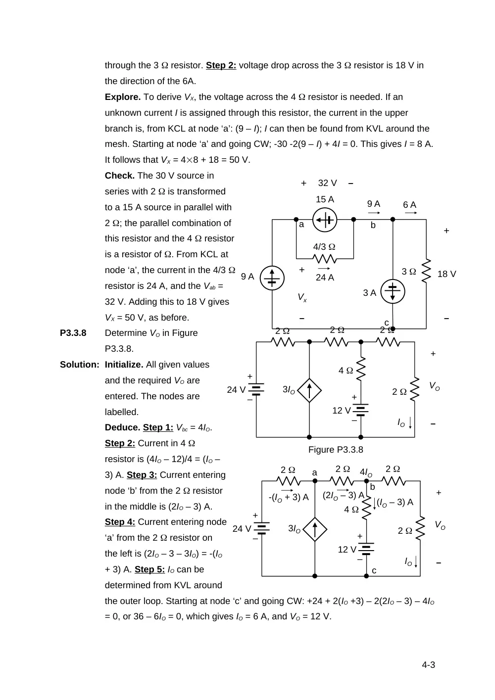
P3.3.8
Determine VO in Figure
P3.3.8.
Solution: Initialize. All given values
and the required VO are
entered. The nodes are
labelled.
Deduce. Step 1: Vbc = 4IO.
Step 2: Current in 4
resistor is (4IO – 12)/4 = (IO –
3) A. Step 3: Current entering
node ‘b’ from the 2 resistor
in the middle is (2IO – 3) A.
Step 4: Current entering node
‘a’ from the 2 resistor on
the left is (2IO – 3 – 3IO) = -(IO
+ 3) A. Step 5: IO can be
determined from KVL around
the outer loop. Starting at node ‘c’ and going CW: +24 + 2(IO +3) – 2(2IO – 3) – 4IO
= 0, or 36 – 6IO = 0, which gives IO = 6 A, and VO = 12 V.
4-3
9 A
3 A
15 A
4/3
3
Vx
24 A
9 A
6 A
32 V
18 V
–
+
–
+
–
+
a
b
c
4
2
2
2
+
–
VO
2
12 V
IO
3IO
24 V
Figure P3.3.8
+
–
+
–
4
2
2
2
+
–
VO
2
12 V
IO
3IO
24 V
+
–
+
–
a
b
c
4IO
(IO – 3) A
(2IO – 3) A
-(IO + 3) A
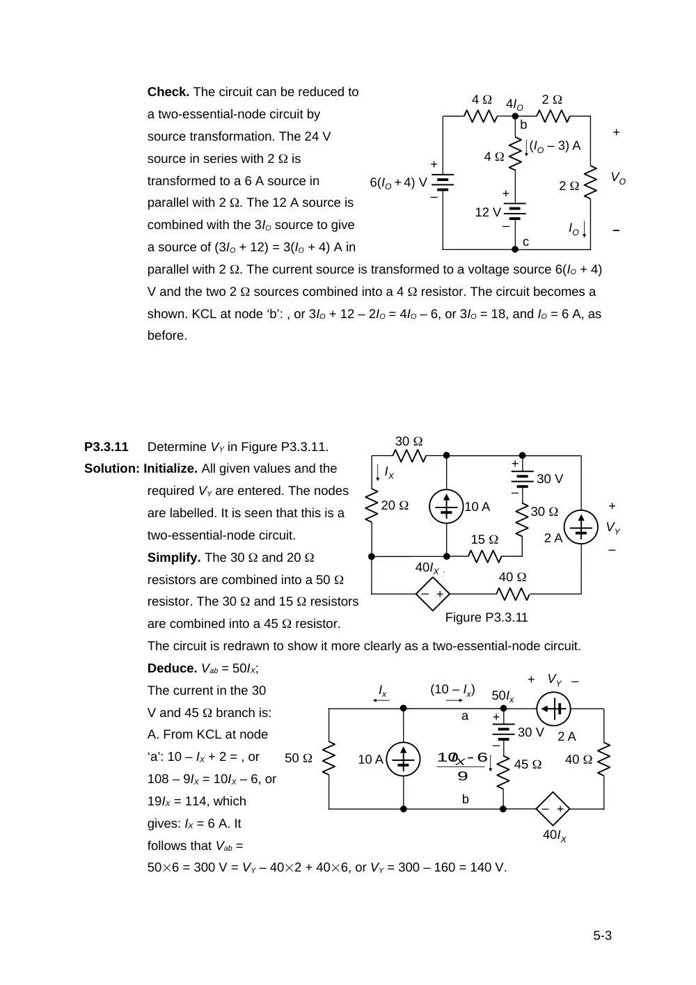
Check. The circuit can be reduced to
a two-essential-node circuit by
source transformation. The 24 V
source in series with 2 is
transformed to a 6 A source in
parallel with 2 . The 12 A source is
combined with the 3IO source to give
a source of (3IO + 12) = 3(IO + 4) A in
parallel with 2 . The current source is transformed to a voltage source 6(IO + 4)
V and the two 2 sources combined into a 4 resistor. The circuit becomes a
shown. KCL at node ‘b’: , or 3IO + 12 – 2IO = 4IO – 6, or 3IO = 18, and IO = 6 A, as
before.
P3.3.11
Determine VY in Figure P3.3.11.
Solution: Initialize. All given values and the
required VY are entered. The nodes
are labelled. It is seen that this is a
two-essential-node circuit.
Simplify. The 30 and 20
resistors are combined into a 50
resistor. The 30 and 15 resistors
are combined into a 45 resistor.
The circuit is redrawn to show it more clearly as a two-essential-node circuit.
Deduce. Vab = 50IX;
The current in the 30
V and 45 branch is:
A. From KCL at node
‘a’: 10 – IX + 2 = , or
108 – 9IX = 10IX – 6, or
19IX = 114, which
gives: IX = 6 A. It
follows that Vab =
506 = 300 V = VY – 402 + 406, or VY = 300 – 160 = 140 V.
5-3
4
2
4
+
–
VO
2
12 V
IO
6(IO + 4) V
+
–
+
–
b
c
4IO
(IO – 3) A
+
–
10 A
30
30
20
15
30 V
–
+
Ix
40Ix
40
2 A
+
–
VY
Figure P3.3.11
IX
40IX
+
–
10 A
45
50
30 V
Ix
2 A
+
–
VY
40IX
40
–
+
(10 – Ix)
50Ix
a
b
9
10 6
IX