
EECE 210 Homework 4, Fall 2015
American University of Beirut · Electric Circuits · 4 pages · Prof. Nassir Sabah

More EECE 210 files
Show the text of this homework
1-2
Figure P4.1.7
VSRC
5 A
6
24
12
8
+
–
VX
+
–
VY
ISRC
a
b
c
d
+
–
Figure P4.1.7-1
VSRC
6
24
12
8
a
b
c
d
+
–
+
– VTh
c
a, d
6
24
8
12
b
Figure P4.1.7-2
+
–
0.4VSRC V
9.6
5 A
b
c
Figure P4.1.7-3
4
120 V
+
–
a
bc
d
+
–
VX
+
–
VY
ISRC
6
Figure P4.1.7-4
Homework 4
P4.1.7
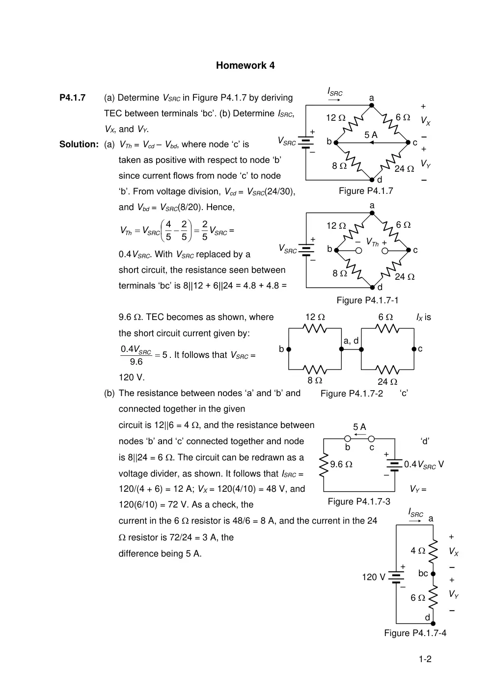
(a) Determine VSRC in Figure P4.1.7 by deriving
TEC between terminals ‘bc’. (b) Determine ISRC,
VX, and VY.
Solution: (a) VTh = Vcd – Vbd, where node ‘c’ is
taken as positive with respect to node ‘b’
since current flows from node ‘c’ to node
‘b’. From voltage division, Vcd = VSRC(24/30),
and Vbd = VSRC(8/20). Hence,
SRC
SRC
Th
V
V
V
5
2
5
2
5
4
=
0.4VSRC. With VSRC replaced by a
short circuit, the resistance seen between
terminals ‘bc’ is 8||12 + 6||24 = 4.8 + 4.8 =
9.6 . TEC becomes as shown, where
IX is
the short circuit current given by:
5
9 6
0 4
.
.
VSRC
. It follows that VSRC =
120 V.
(b) The resistance between nodes ‘a’ and ‘b’ and
‘c’
connected together in the given
circuit is 12||6 = 4 , and the resistance between
nodes ‘b’ and ‘c’ connected together and node
‘d’
is 8||24 = 6 . The circuit can be redrawn as a
voltage divider, as shown. It follows that ISRC =
120/(4 + 6) = 12 A; VX = 120(4/10) = 48 V, and
VY =
120(6/10) = 72 V. As a check, the
current in the 6 resistor is 48/6 = 8 A, and the current in the 24
resistor is 72/24 = 3 A, the
difference being 5 A.
2-2
10
5
–
+VTh
5 V
10
5 V
1 A
10
Figure P4.1.11
+
–
+
–
a
b
10
5
–
+VTh
5 V
10
5 V
1 A
10
Figure P4.1.11-1
+
–
+
–
a
b
c
d
e
+
–
12 V
1
1
P4.1.21
–
+
1
IX
2IX
a
b
+
–
12 V
1
1
P4.1.21-1
–
+
1
IX
2IX
a
b
RL
IX V
IX
0
c
1
1
P4.1.21-2
–
+
1
IX
2IX
a
b
IX V
2IX
IX
c
+
–
VT
P4.1.11
Derive TEC looking into terminals ‘ab’ in Figure
P4.1.11.
Solution: Initialize. All given values and the
required VTh are entered. The
nodes are labeled.
Simplify. The circuit is in a
Simple enough form.
Deduce. The 1 A source current
flows through the 5 resistor,
producing
a voltage drop of 5 V. The current
through the upper 10 resistor is zero, so that
the
current through the lower 10 resistor is zero, and
the voltage across this resistor is zero. From KVL starting at node ‘b and going
CW:-5 + 0 + 5 – VTh = 0, which gives VTh = 0.
To determine RTh, the sources are set to zero. The 10 resistor on the left is
short-circuited, leaving the remaining resistors in series. It follows that RTh = 25 .
P4.1.21
Connect a resistor RL between terminals ‘ab’ in
Figure P4.1.21 and show that the voltage
Vab is independent of RL. Deduce that
TEC looking into terminals ‘ab’ is an ideal
voltage source. Verify this deduction by
determining VTh and RTh looking into terminals ‘ab’.
Solution: Vcb = IX V, Vac = IX V, Iac = IX A, and
current through 12 V source is zero,
it follows that Vcb = IX V = 12 V, Vab =
2IX V = 24 V, independently of RL,
Hence, VTh = 24 V, RTh = 0.
On opencircuit Vcb = 12 V = IX so that
VTh = Vab = 24 V. If at test source is applied,
Icb through the 1 resistor on the LHS
Is IX; Iac = 2IX and Vab across the resistors
Is 3IX, which equals the source voltage 2IX.
It follows that IX = 0 so that the trst source
3-2
Figure P4.1.28
5
5
10
a
b
20 V
2IX
IX
+
–
Figure P4.1.28-1
5
5
10
a
b
20 V
2IX
IX
+
–
IX
3IX
2IX
c
d
Figure P4.1.28-2
5
5
10
a
b
2IX
IX
IT + IX
IT + 3IX
IT + 2IX
+
–
IT
VT
c
d
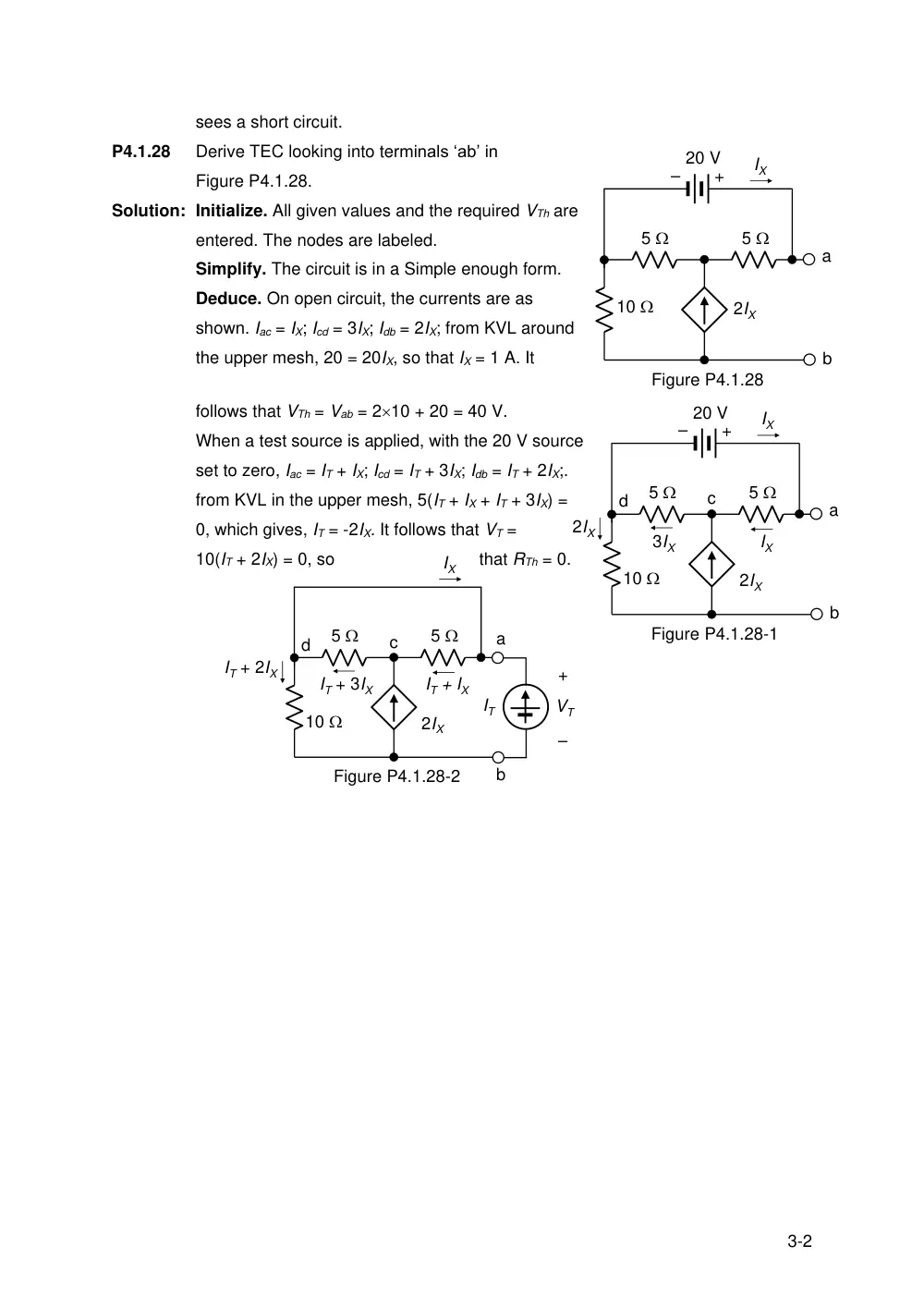
sees a short circuit.
P4.1.28
Derive TEC looking into terminals ‘ab’ in
Figure P4.1.28.
Solution: Initialize. All given values and the required VTh are
entered. The nodes are labeled.
Simplify. The circuit is in a Simple enough form.
Deduce. On open circuit, the currents are as
shown. Iac = IX; Icd = 3IX; Idb = 2IX; from KVL around
the upper mesh, 20 = 20IX, so that IX = 1 A. It
follows that VTh = Vab = 210 + 20 = 40 V.
When a test source is applied, with the 20 V source
set to zero, Iac = IT + IX; Icd = IT + 3IX; Idb = IT + 2IX;.
from KVL in the upper mesh, 5(IT + IX + IT + 3IX) =
0, which gives, IT = -2IX. It follows that VT =
10(IT + 2IX) = 0, so
that RTh = 0.
4-2
10 V
2
2
4
5IX A
4
IX
–
+
VO
a
b
c
+
–
Figure P4.1.30
10 V
2
2
4
–
+
VTh
a
b
c
+
–
Figure P4.1.30-1
d
10 V
2
2
5ISC
4
ISC
a
b
c
+
–
Figure P4.1.30-2
d
2.5 A
+
–
10 V
4
–
+
VO
Figure P4.1.30-3
-16
P4.1.30
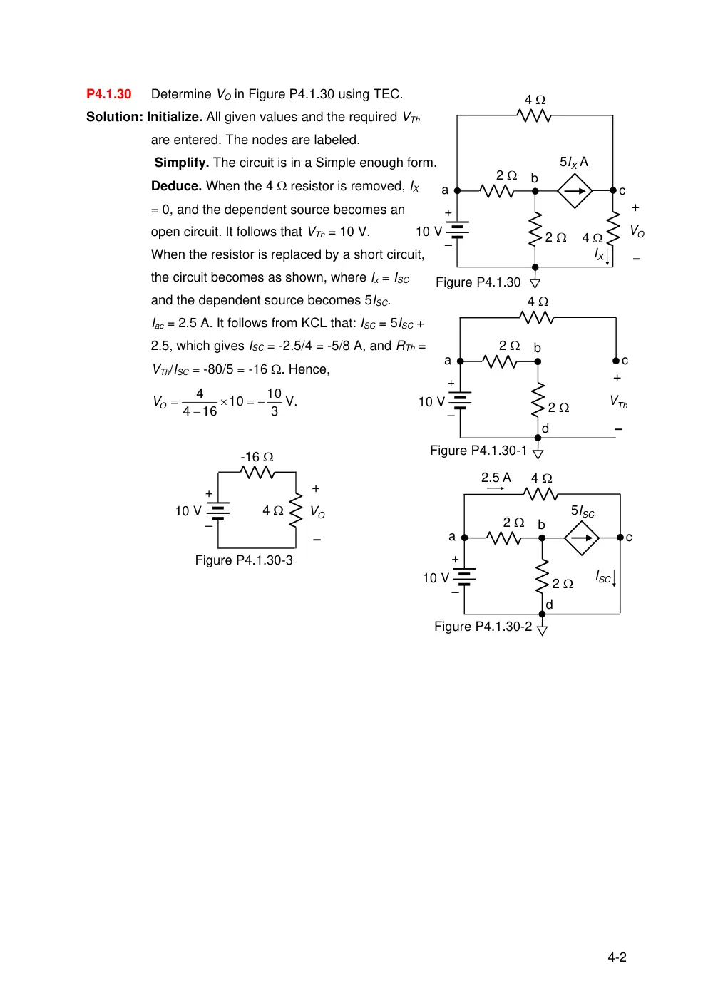
Determine VO in Figure P4.1.30 using TEC.
Solution: Initialize. All given values and the required VTh
are entered. The nodes are labeled.
Simplify. The circuit is in a Simple enough form.
Deduce. When the 4 resistor is removed, IX
= 0, and the dependent source becomes an
open circuit. It follows that VTh = 10 V.
When the resistor is replaced by a short circuit,
the circuit becomes as shown, where Ix = ISC
and the dependent source becomes 5ISC.
Iac = 2.5 A. It follows from KCL that: ISC = 5ISC +
2.5, which gives ISC = -2.5/4 = -5/8 A, and RTh =
VTh/ISC = -80/5 = -16 . Hence,
3
10
10
16
4
4
VO
V.