
EECE 210 Homework 4 with Solution, Fall 2013
American University of Beirut · Electric Circuits · 4 pages · with solution


More EECE 210 files
Show the text of this homework
Homework 4
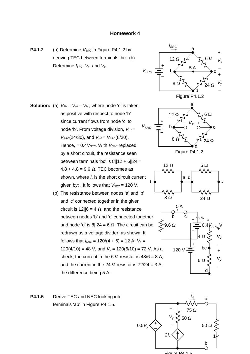
P4.1.2
(a) Determine VSRC in Figure P4.1.2 by
deriving TEC between terminals ‘bc’. (b)
Determine ISRC, Vx, and Vy.
Solution: (a) VTh = Vcd – Vbd, where node ‘c’ is taken
as positive with respect to node ‘b’
since current flows from node ‘c’ to
node ‘b’. From voltage division, Vcd =
VSRC(24/30), and Vbd = VSRC(8/20).
Hence, = 0.4VSRC. With VSRC replaced
by a short circuit, the resistance seen
between terminals ‘bc’ is 8||12 + 6||24 =
4.8 + 4.8 = 9.6 . TEC becomes as
shown, where Ix is the short circuit current
given by: . It follows that VSRC = 120 V.
(b) The resistance between nodes ‘a’ and ‘b’
and ‘c’ connected together in the given
circuit is 12||6 = 4 , and the resistance
between nodes ‘b’ and ‘c’ connected together
and node ‘d’ is 8||24 = 6 . The circuit can be
redrawn as a voltage divider, as shown. It
follows that ISRC = 120/(4 + 6) = 12 A; Vx =
120(4/10) = 48 V, and Vy = 120(6/10) = 72 V. As a
check, the current in the 6 resistor is 48/6 = 8 A,
and the current in the 24 resistor is 72/24 = 3 A,
the difference being 5 A.
P4.1.5
Derive TEC and NEC looking into
terminals ‘ab’ in Figure P4.1.5.
1-4
Figure P4.1.2
VSRC
6
24
12
8
a
b
c
d
+
–
+
– VTh
c
a, d
6
24
8
12
b
4
120 V
+
–
a
bc
d
+
–
Vx
+
–
Vy
ISRC
6
Figure P4.1.2
VSRC
5 A
6
24
12
8
+
–
Vx
+
–
Vy
ISRC
a
b
c
d
+
–
+
–
0.4VSRC V
9.6
5 A
b
c
–
+
Ix
2Ix
–
+
Vy
0.5Vy
50
a
b
Figure P4 1 5
75
50
Solution: Since there are no independent
sources in the circuit, VTh and IN are
zero. To determine RN, a test current
source IT is applied, as shown. The
CCCS becomes 2IT of reversed
polarity. Vy = -502IT =
-100IT. The CCVS becomes
0.5(-100IT) = -50IT. It follows that VT = 75IT – 50IT, so that RTh = RN = VT /IT = 75 –
50 = 25 .
P4.1.17
Determine VO in Figure P4.1.17 using
TEC.
Solution: From KVL around the mesh that
includes the 10 V source, 10 = (20
+ 10)Ix, so Ix = 1/3 A. From KVL
around the loop on the LHS, VTh =
20 + 10 – 20Ix = 30 – 20/3 = 70/3
V. With both sources set to zero,
the 80 resistor is short circuited,
so that RTh = 10||20 = 20/3 . It
follows that VO = V.
P4.2.1
Determine, according to the substitution theorem, (a) the independent voltage
source, (b) the independent current
source,
and (c) the resistance that can replace
the
dependent current source without
affecting the rest of the circuit.
Solution: From KCL, 3 = 3Ix, so Ix = 1 A. From
KVL, Vx
2-4
–
+
IT
2IT
–
+
Vy
-50IT
50
a
b
75
IT
–
+
VT
10 V
10
20
40
80
20 V
+
–
VO
+
–
+
–
Figure P4.1.17
10 V
10
20
80
20 V
a
b
+
–
+
–
Ix
+
–
VTh
Figure P4.2.1
3 A
2
+
–
2 V
Ix
2Ix
= 2 + 21 = 4 V. It follows that the 2Ix source can be replaced by: (a) an
independent voltage source of 4 V, (b) an independent current source of 2 A, or
(c) a resistance of 4/2 = 2 .
P4.2.5
Determine IO in Figure P4.2.5 by
using the substitution theorem
and by deriving TEC between
nodes ‘ab’, where NA is an
unspecified circuit having a
voltage of 15.5 V.
3-4
10 V
4 S
2 S
2 S
4 S
2 S
2 A
IO
NA
–
+
15.5 V
Figure P4.2.5
a
b
+
–
Solution: From Ohm’s law, the current in
the 2 S resistor flowing away
from node ‘a’ is 15.52 = 31 A.
From KCL, IN = 33 A. when the
independent sources are set to
zero, the input conductance GN
seen looking into terminals ‘ab’ is
2 S. NEC connected to the 4 S
conductance is as shown. It
follows that A.
4-4
2 S
4 S
33 A
b
10 V
4 S
2 S
2 S
2 S
2 A
IN
15.5 V
a
b
+
–
31 A
+
–