
EECE 210 Homework 4 with Solution, Fall 2014
American University of Beirut · Electric Circuits · 5 pages · with solution
More EECE 210 files
Show the text of this homework
60
20
a
b
30
+
–
20 V
+
–
60 V
1 A
2 A
+
–
VTh
I
c
d
+
–
60I
10
5
–
+VTh
5 V
10
5 V
1 A
10
Figure P4.1.14
+
–
+
–
a
b
10
5
–
+VTh
5 V
10
5 V
1 A
10
e
b
c
d
1 A
–
+
5 V
+
–
+
–
I = 0
I = 0
–
+
0 V
Homework 4
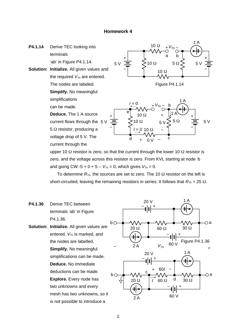
P4.1.14
Derive TEC looking into
terminals
‘ab’ in Figure P4.1.14.
Solution: Initialize. All given values and
the required VTh are entered.
The nodes are labeled.
Simplify. No meaningful
simplifications
can be made.
Deduce. The 1 A source
current flows through the
5 resistor, producing a
voltage drop of 5 V. The
current through the
upper 10 resistor is zero, so that the current through the lower 10 resistor is
zero, and the voltage across this resistor is zero. From KVL starting at node ‘b
and going CW:-5 + 0 + 5 – VTh = 0, which gives VTh = 0.
To determine RTh, the sources are set to zero. The 10 resistor on the left is
short-circuited, leaving the remaining resistors in series. It follows that RTh = 25 .
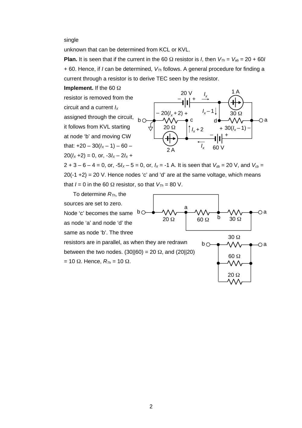
P4.1.36
Derive TEC between
terminals ‘ab’ in Figure
P4.1.36.
Solution: Initialize. All given values are
entered. VTh is marked, and
the nodes are labelled.
Simplify. No meaningful
simplifications can be made.
Deduce. No immediate
deductions can be made.
Explore. Every node has
two unknowns and every
mesh has two unknowns, so it
is not possible to introduce a
1
60
20
a
b
30
+
–
20 V
+
–
60 V Figure P4.1.36
1 A
2 A
single
unknown that can be determined from KCL or KVL.
Plan. It is seen that if the current in the 60 resistor is I, then VTh = Vab = 20 + 60I
+ 60. Hence, if I can be determined, VTh follows. A general procedure for finding a
current through a resistor is to derive TEC seen by the resistor.
Implement. If the 60
resistor is removed from the
circuit and a current IX
assigned through the circuit,
it follows from KVL starting
at node ‘b’ and moving CW
that: +20 – 30(IX – 1) – 60 –
20(IX +2) = 0, or, -3IX – 2IX +
2 + 3 – 6 – 4 = 0, or, -5IX – 5 = 0, or, IX = -1 A. It is seen that Vdb = 20 V, and Vcb =
20(-1 +2) = 20 V. Hence nodes ‘c’ and ‘d’ are at the same voltage, which means
that I = 0 in the 60 resistor, so that VTh = 80 V.
To determine RTh, the
sources are set to zero.
Node ‘c’ becomes the same
as node ‘a’ and node ‘d’ the
same as node ‘b’. The three
resistors are in parallel, as when they are redrawn
between the two nodes. (30||60) = 20 , and (20||20)
= 10 . Hence, RTh = 10 .
2
20
a
b
30
+
–
20 V
+
–
60 V
1 A
2 A
c
d
Ix
Ix
Ix – 1
+
30(Ix – 1) –
Ix + 2
+
– 20(Ix + 2)
60
20
a
b
30
a
b
b
a
30
60
20
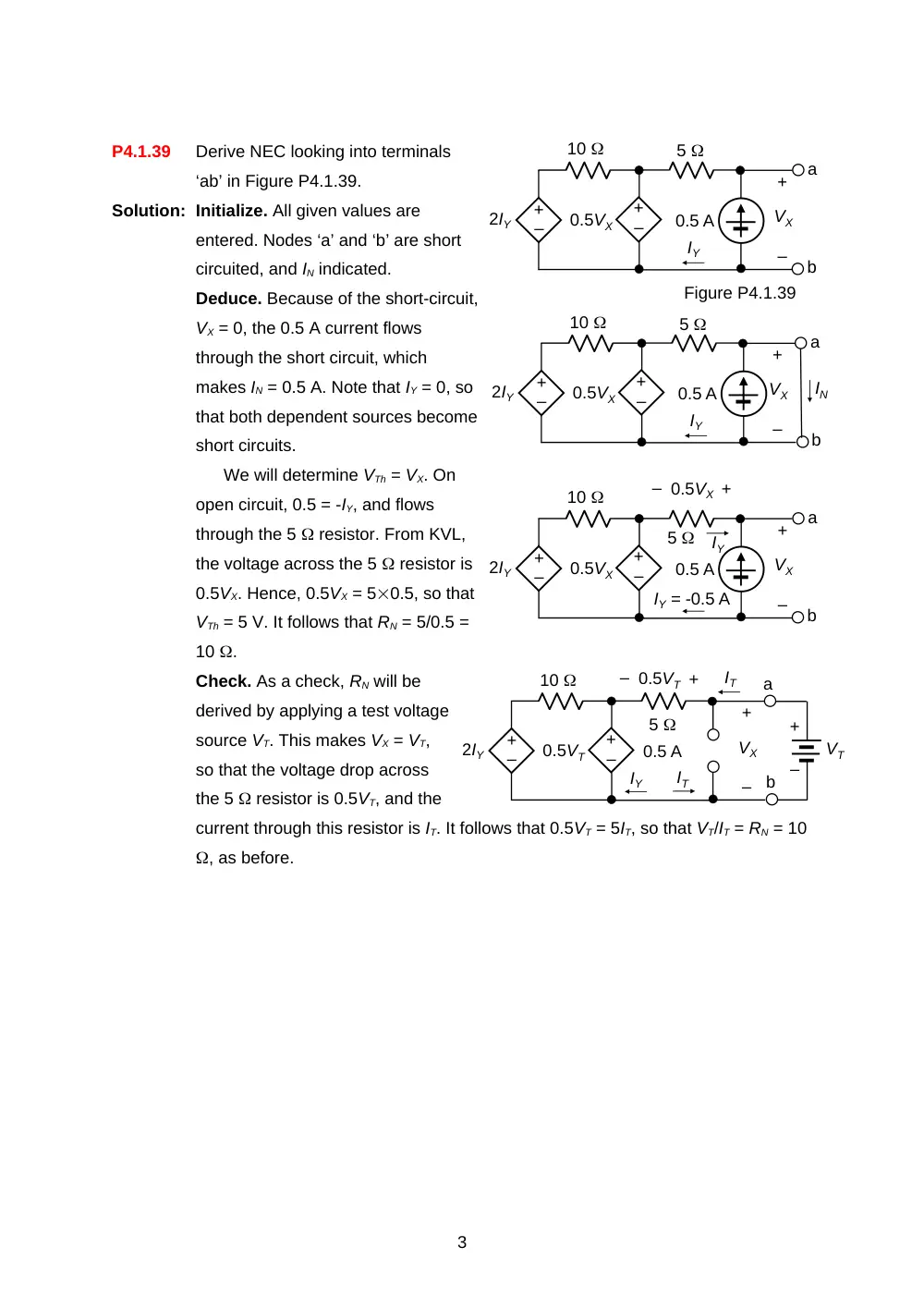
P4.1.39
Derive NEC looking into terminals
‘ab’ in Figure P4.1.39.
Solution: Initialize. All given values are
entered. Nodes ‘a’ and ‘b’ are short
circuited, and IN indicated.
Deduce. Because of the short-circuit,
VX = 0, the 0.5 A current flows
through the short circuit, which
makes IN = 0.5 A. Note that IY = 0, so
that both dependent sources become
short circuits.
We will determine VTh = VX. On
open circuit, 0.5 = -IY, and flows
through the 5 resistor. From KVL,
the voltage across the 5 resistor is
0.5VX. Hence, 0.5VX = 50.5, so that
VTh = 5 V. It follows that RN = 5/0.5 =
10 .
Check. As a check, RN will be
derived by applying a test voltage
source VT. This makes VX = VT,
so that the voltage drop across
the 5 resistor is 0.5VT, and the
current through this resistor is IT. It follows that 0.5VT = 5IT, so that VT/IT = RN = 10
, as before.
3
–
+
2IY
0.5VX
0.5 A
10
IY
–
+
VX
a
b
+
–
Figure P4.1.39
5
–
+
2IY
0.5VX
0.5 A
10
IY
–
+
VX
a
b
+
–
5
IN
–
+
2IY
0.5VX
0.5 A
10
IY = -0.5 A
–
+
VX
a
b
+
–
5
IY
+
– 0.5VX
–
+
2IY
0.5VT
0.5 A
10
IY
–
+
VX
a
b
+
–
5
+
–
IT
VT
IT
– 0.5VT +
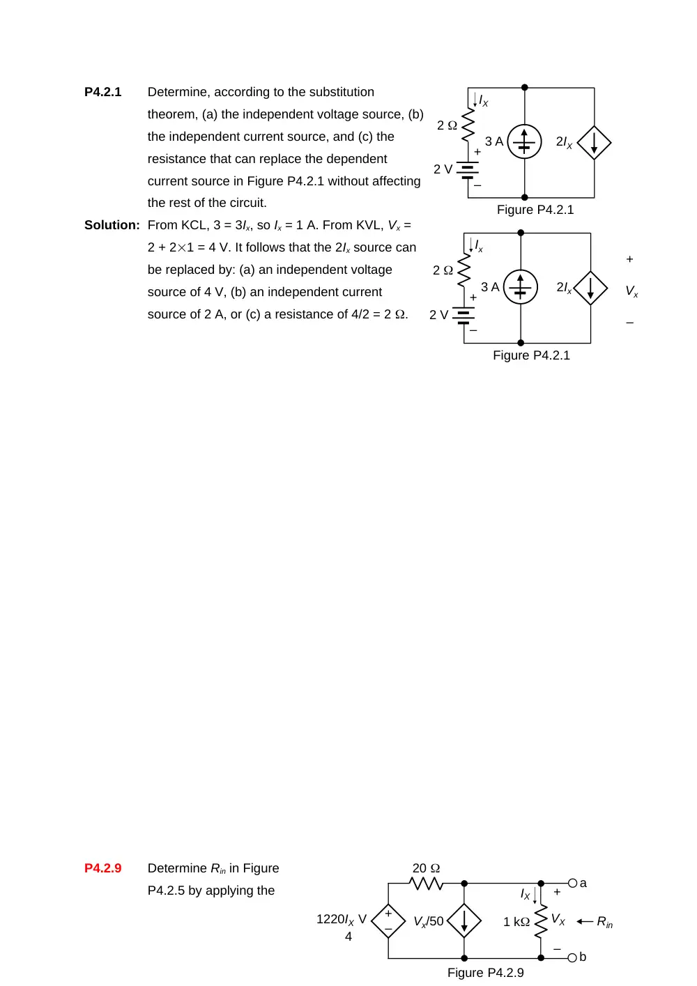
P4.2.1
Determine, according to the substitution
theorem, (a) the independent voltage source, (b)
the independent current source, and (c) the
resistance that can replace the dependent
current source in Figure P4.2.1 without affecting
the rest of the circuit.
Solution: From KCL, 3 = 3Ix, so Ix = 1 A. From KVL, Vx =
2 + 21 = 4 V. It follows that the 2Ix source can
be replaced by: (a) an independent voltage
source of 4 V, (b) an independent current
source of 2 A, or (c) a resistance of 4/2 = 2 .
P4.2.9
Determine Rin in Figure
P4.2.5 by applying the
4
Figure P4.2.1
3 A
2
+
–
2 V
Ix
2Ix
+
–
Vx
Figure P4.2.1
3 A
2
+
–
2 V
IX
2IX
–
+
1220IX V
Vx/50
1 k
20
IX
–
+
VX
a
b
Rin
Figure P4.2.9
source absorption theorem, where IX is in amperes.
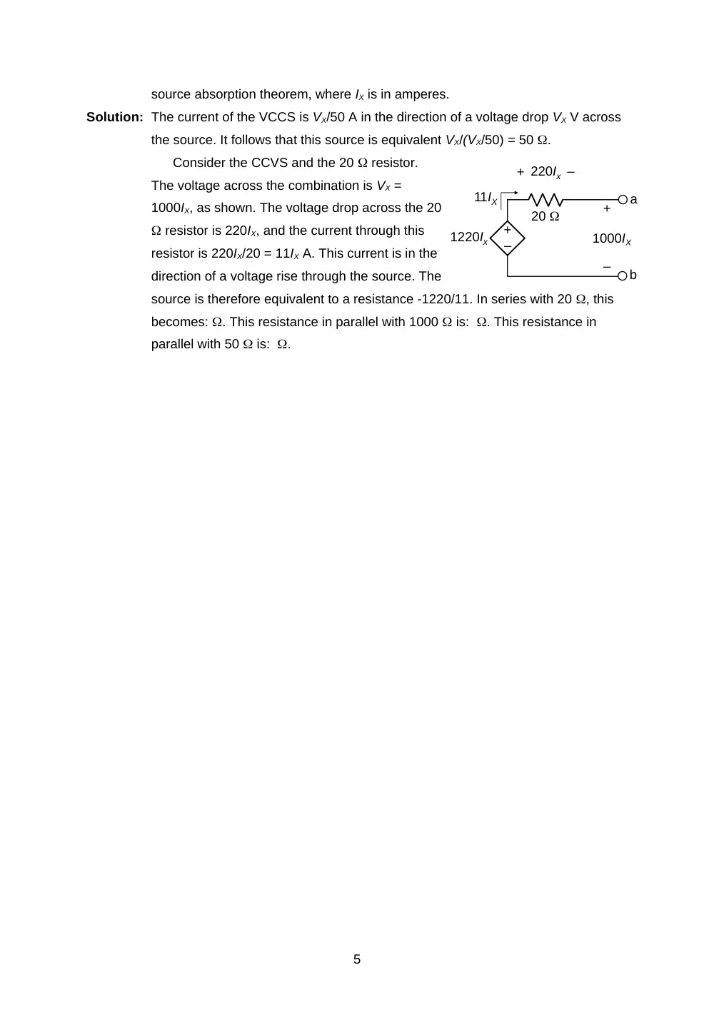
Solution: The current of the VCCS is VX/50 A in the direction of a voltage drop VX V across
the source. It follows that this source is equivalent VX/(VX/50) = 50 .
Consider the CCVS and the 20 resistor.
The voltage across the combination is VX =
1000IX, as shown. The voltage drop across the 20
resistor is 220IX, and the current through this
resistor is 220IX/20 = 11IX A. This current is in the
direction of a voltage rise through the source. The
source is therefore equivalent to a resistance -1220/11. In series with 20 , this
becomes: . This resistance in parallel with 1000 is: . This resistance in
parallel with 50 is: .
5
–
+
1220Ix
20
–
+
a
b
1000IX
–
+ 220Ix
11IX