
EECE 210 Homework 5, Fall 2015
American University of Beirut · Electric Circuits · 5 pages · Prof. Nassir Sabah
More EECE 210 files
Show the text of this homework
1-2
Homework 5
P4.1.50
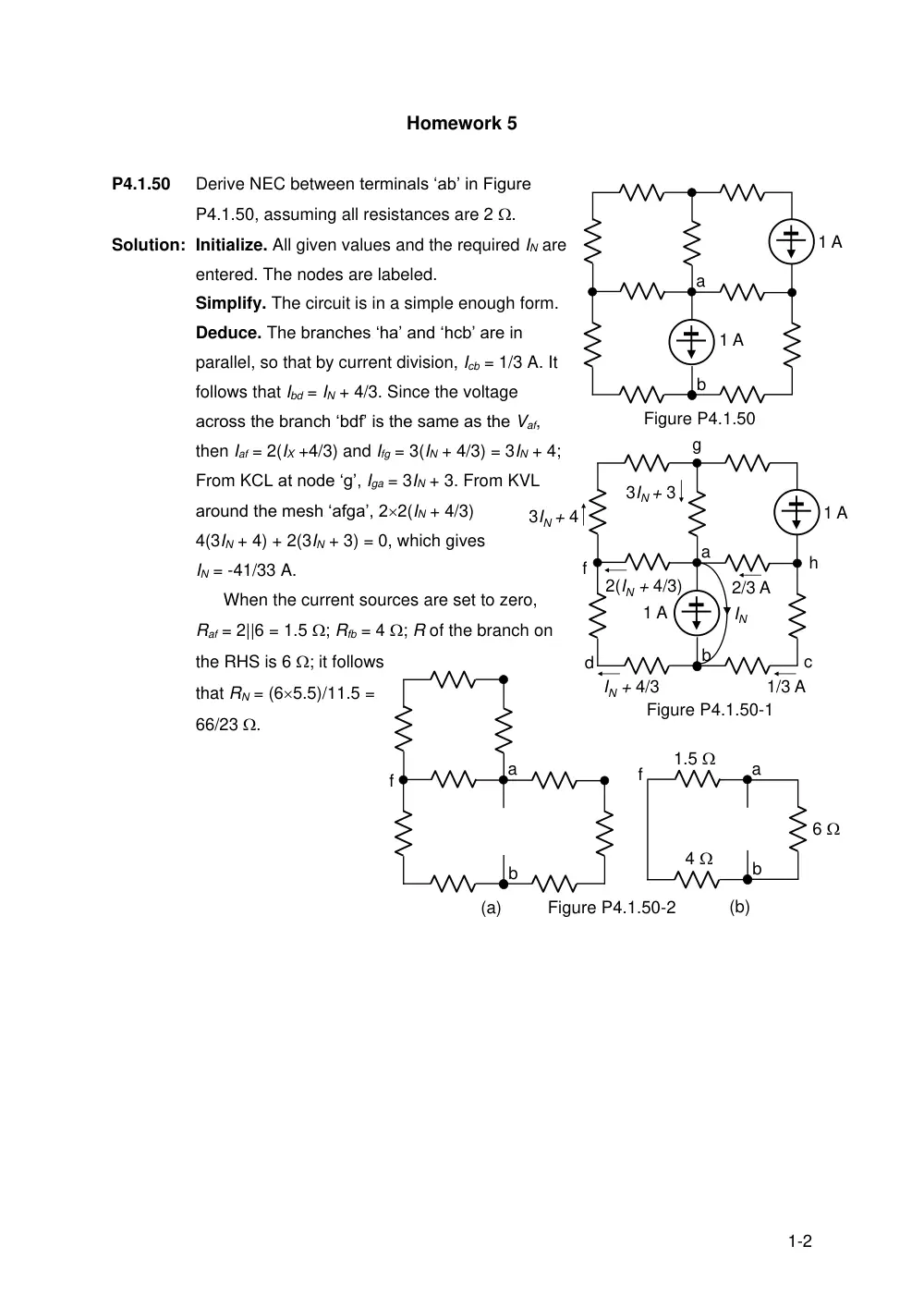
Derive NEC between terminals ‘ab’ in Figure
P4.1.50, assuming all resistances are 2 .
Solution: Initialize. All given values and the required IN are
entered. The nodes are labeled.
Simplify. The circuit is in a simple enough form.
Deduce. The branches ‘ha’ and ‘hcb’ are in
parallel, so that by current division, Icb = 1/3 A. It
follows that Ibd = IN + 4/3. Since the voltage
across the branch ‘bdf’ is the same as the Vaf,
then Iaf = 2(IX +4/3) and Ifg = 3(IN + 4/3) = 3IN + 4;
From KCL at node ‘g’, Iga = 3IN + 3. From KVL
around the mesh ‘afga’, 22(IN + 4/3)
4(3IN + 4) + 2(3IN + 3) = 0, which gives
IN = -41/33 A.
When the current sources are set to zero,
Raf = 2||6 = 1.5 ; Rfb = 4 ; R of the branch on
the RHS is 6 ; it follows
that RN = (65.5)/11.5 =
66/23 .
1 A
a
1 A
b
Figure P4.1.50
1 A
a
1 A
b
Figure P4.1.50-1
IN
1/3 A
IN + 4/3
3IN + 4
c
d
f
g
h
2/3 A
2(IN + 4/3)
3IN + 3
a
b
Figure P4.1.50-2
a
b
6
4
1.5
(a)
(b)
f
f
2-2
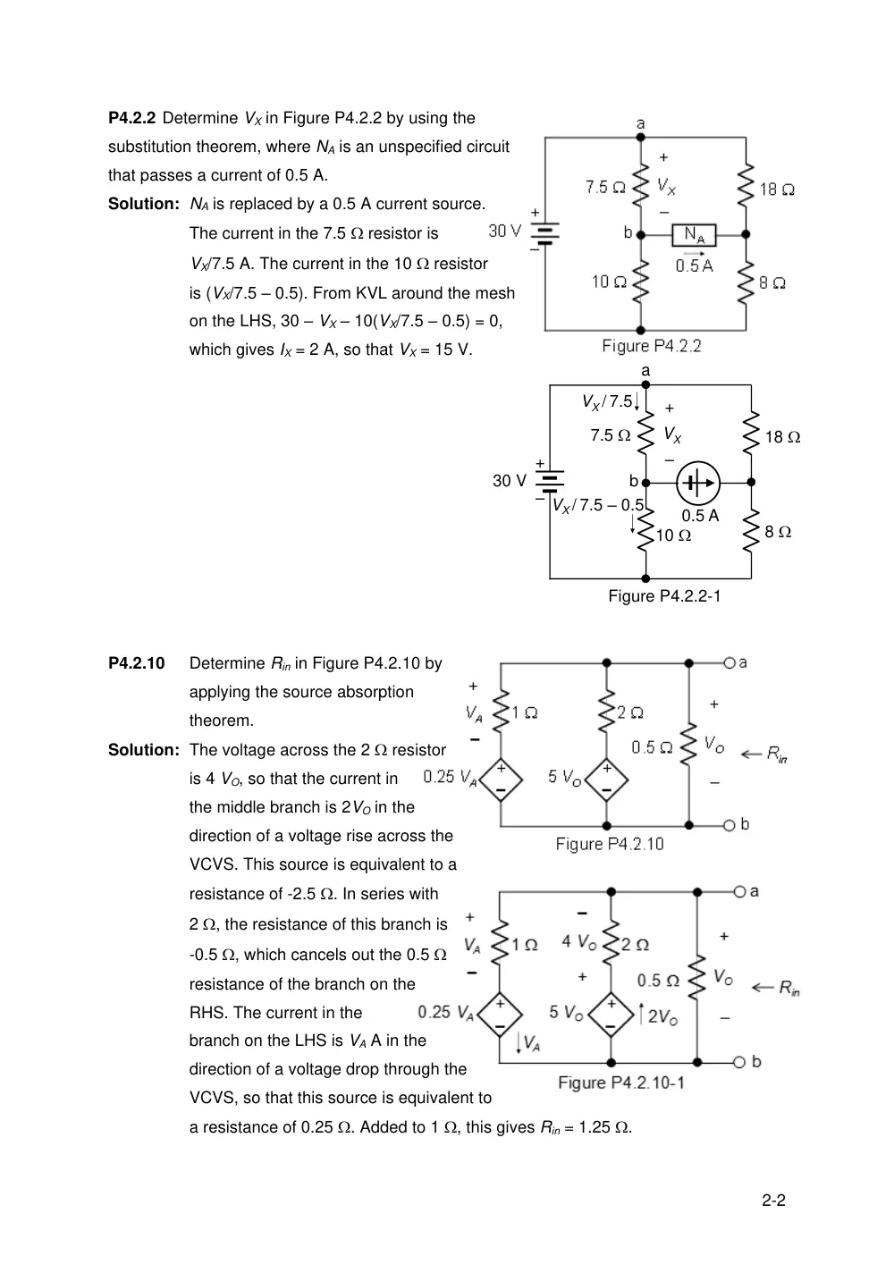
P4.2.2 Determine VX in Figure P4.2.2 by using the
substitution theorem, where NA is an unspecified circuit
that passes a current of 0.5 A.
Solution: NA is replaced by a 0.5 A current source.
The current in the 7.5 resistor is
VX/7.5 A. The current in the 10 resistor
is (VX/7.5 – 0.5). From KVL around the mesh
on the LHS, 30 – VX – 10(VX/7.5 – 0.5) = 0,
which gives IX = 2 A, so that VX = 15 V.
P4.2.10
Determine Rin in Figure P4.2.10 by
applying the source absorption
theorem.
Solution: The voltage across the 2 resistor
is 4 VO, so that the current in
the middle branch is 2VO in the
direction of a voltage rise across the
VCVS. This source is equivalent to a
resistance of -2.5 . In series with
2 , the resistance of this branch is
-0.5 , which cancels out the 0.5
resistance of the branch on the
RHS. The current in the
branch on the LHS is VA A in the
direction of a voltage drop through the
VCVS, so that this source is equivalent to
a resistance of 0.25 . Added to 1 , this gives Rin = 1.25 .
Figure P4.2.2-1
+
–
30 V
7.5
18
10
8
0.5 A
+
–
VX
a
b
VX / 7.5
VX / 7.5 – 0.5
3-2
P5.1.10
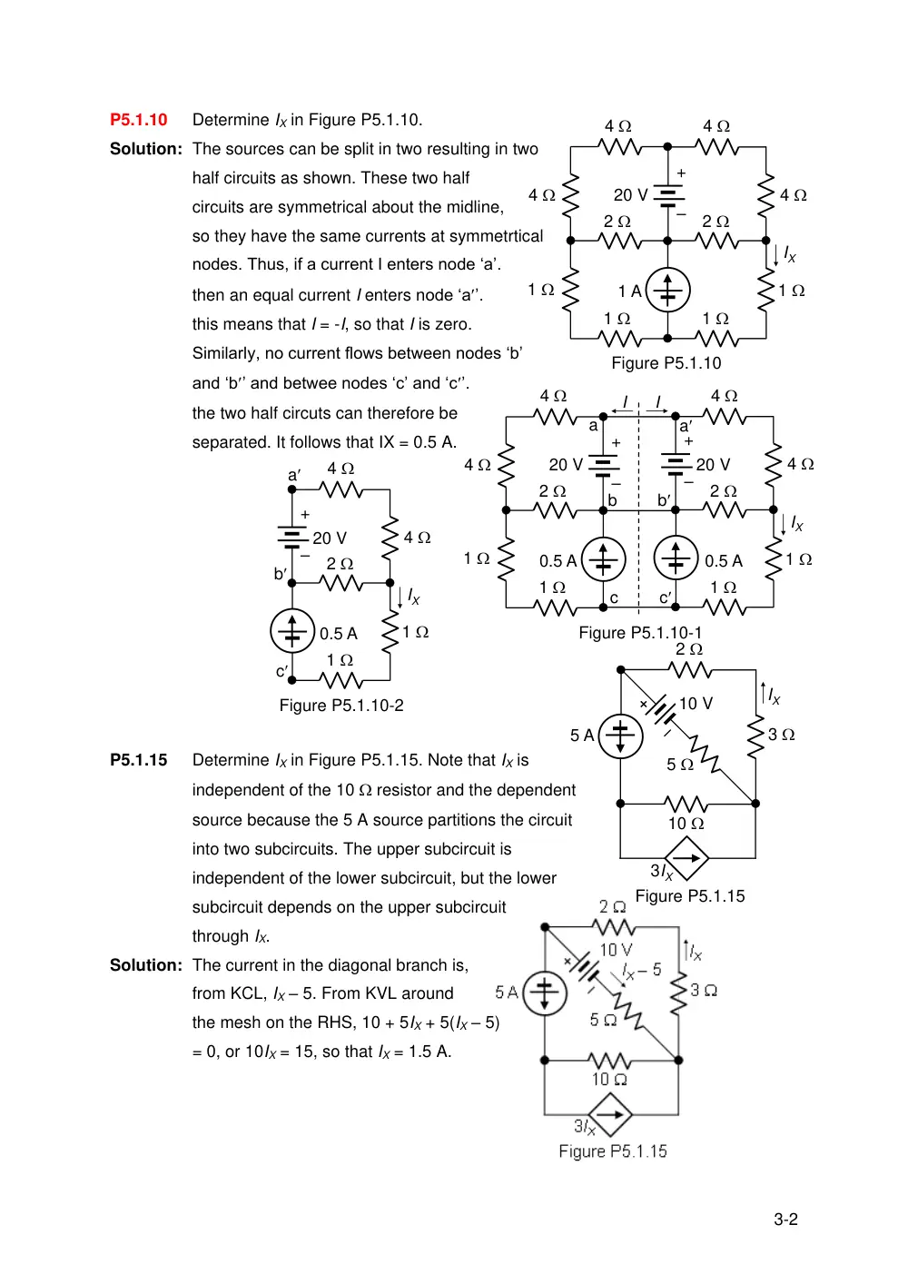
Determine IX in Figure P5.1.10.
Solution: The sources can be split in two resulting in two
half circuits as shown. These two half
circuits are symmetrical about the midline,
so they have the same currents at symmetrtical
nodes. Thus, if a current I enters node ‘a’.
then an equal current I enters node ‘a’.
this means that I = -I, so that I is zero.
Similarly, no current flows between nodes ‘b’
and ‘b’ and betwee nodes ‘c’ and ‘c’.
the two half circuts can therefore be
separated. It follows that IX = 0.5 A.
P5.1.15
Determine IX in Figure P5.1.15. Note that IX is
independent of the 10 resistor and the dependent
source because the 5 A source partitions the circuit
into two subcircuits. The upper subcircuit is
independent of the lower subcircuit, but the lower
subcircuit depends on the upper subcircuit
through IX.
Solution: The current in the diagonal branch is,
from KCL, IX – 5. From KVL around
the mesh on the RHS, 10 + 5IX + 5(IX – 5)
= 0, or 10IX = 15, so that IX = 1.5 A.
20 V
+
–
1
1
1
1
2
2
4
4
4
4
IX
1 A
Figure P5.1.10
20 V
+
–
1
1
1
1
2
2
4
4
4
4
IX
0.5 A
Figure P5.1.10-1
+
–
20 V
a
a
b
b
c
c
0.5 A
I
I
1
1
2
4
4
IX
Figure P5.1.10-2
+
–
20 V
a
b
c
0.5 A
10 V
5 A
2
10
Figure P5.1.15
3
5
IX
3IX
4-2
P5.1.22
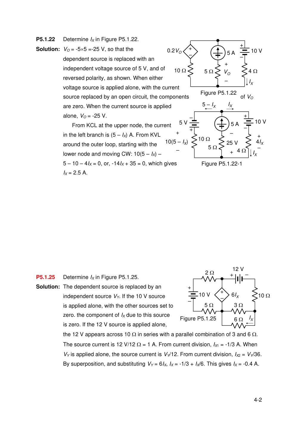
Determine IX in Figure P5.1.22.
Solution: VO = -55 =-25 V, so that the
dependent source is replaced with an
independent voltage source of 5 V, and of
reversed polarity, as shown. When either
voltage source is applied alone, with the current
source replaced by an open circuit, the components
of VO
are zero. When the current source is applied
alone, VO = -25 V.
From KCL at the upper node, the current
in the left branch is (5 – IX) A. From KVL
around the outer loop, starting with the
lower node and moving CW: 10(5 – IX) –
5 – 10 – 4IX = 0, or, -14IX + 35 = 0, which gives
IX = 2.5 A.
P5.1.25
Determine IX in Figure P5.1.25.
Solution: The dependent source is replaced by an
independent source VY. If the 10 V source
is applied alone, with the other sources set to
zero. the component of IX due to this source
is zero. If the 12 V source is applied alone,
the 12 V appears across 10 in series with a parallel combination of 3 and 6 .
The source current is 12 V/12 = 1 A. From current division, IX1 = -1/3 A. When
VY is applied alone, the source current is VY/12. From current division, IX2 = VY/36.
By superposition, and substituting VY = 6IX, IX = -1/3 + IX/6. This gives IX = -0.4 A.
5
5 A
10
+
–
4
10 V
Figure P5.1.22
+
–
VO
–
+
0.2VO
IX
5
5 A
10
+
–
4
10 V
+
–
25 V
IX
+
–
5 V
IX
5 – IX
+
–
4IX
+
–
10(5 – IX)
Figure P5.1.22-1
Figure P5.1.25
+
–
10
12 V
IX
6
3
5
+
–
10 V
2
–
+
6IX
5-2
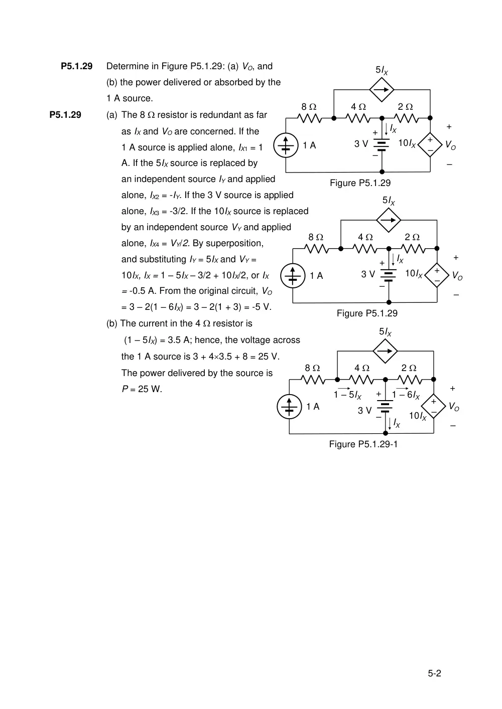
P5.1.29
Determine in Figure P5.1.29: (a) VO, and
(b) the power delivered or absorbed by the
1 A source.
P5.1.29
(a) The 8 resistor is redundant as far
as IX and VO are concerned. If the
1 A source is applied alone, IX1 = 1
A. If the 5IX source is replaced by
an independent source IY and applied
alone, IX2 = -IY. If the 3 V source is applied
alone, IX3 = -3/2. If the 10IX source is replaced
by an independent source VY and applied
alone, IX4 = VY/2. By superposition,
and substituting IY = 5IX and VY =
10IX, IX = 1 – 5IX – 3/2 + 10IX/2, or IX
= -0.5 A. From the original circuit, VO
= 3 – 2(1 – 6IX) = 3 – 2(1 + 3) = -5 V.
(b) The current in the 4 resistor is
(1 – 5IX) = 3.5 A; hence, the voltage across
the 1 A source is 3 + 43.5 + 8 = 25 V.
The power delivered by the source is
P = 25 W.
–
+
+
–
8
4
2
10IX
1 A
3 V
IX
+
–
VO
Figure P5.1.29
5IX
–
+
+
–
8
4
2
10IX
1 A
3 V
IX
+
–
VO
Figure P5.1.29
5IX
–
+
+
–
8
4
2
10IX
1 A
3 V
IX
+
–
VO
Figure P5.1.29-1
5IX
1 – 5IX
1 – 6IX