
EECE 210 Homework 5 with Solution, Fall 2014
American University of Beirut · Electric Circuits · 7 pages · with solution



More EECE 210 files
Show the text of this homework
Chapter 5 –Circuit Simplification
P5.1.7 Determine IX in Figure P5.1.7.
Solution: Initialize.All given values and the required
IX are entered.
Simplify. No meaningful simplifications
can be made.
Deduce. Step 1:VO = -55 =-25 V,so that
the dependent source is replaced with an
independent voltage source of 5 V, with
reversed polarity, as shown.Step 2:The 5
resistor is now redundant as far as the rest of
the circuit is concerned and can be removed.
Implement.IX can be determined by
superposition. With the 5 V source applied alone, IX1 = -5/14 A. With the 10 V
source applied alone, IX2 = -10/14. With the 5 A source applied alone, IX3 =
510/14. It follows that IX = (-5 – 10 + 50)/14 = 35/14 = 2.5 A.
Check. The circuit is a two-
essential node circuit. The
voltage of the upper node with
respect to the lower node is (10
+ 4IX) V. From KCL at the upper
node, 5 = IX + (15 + 4IX)/10, or 50
= 10IX + 15 + 4IX, or IX = 35/14 =
2.5 A.
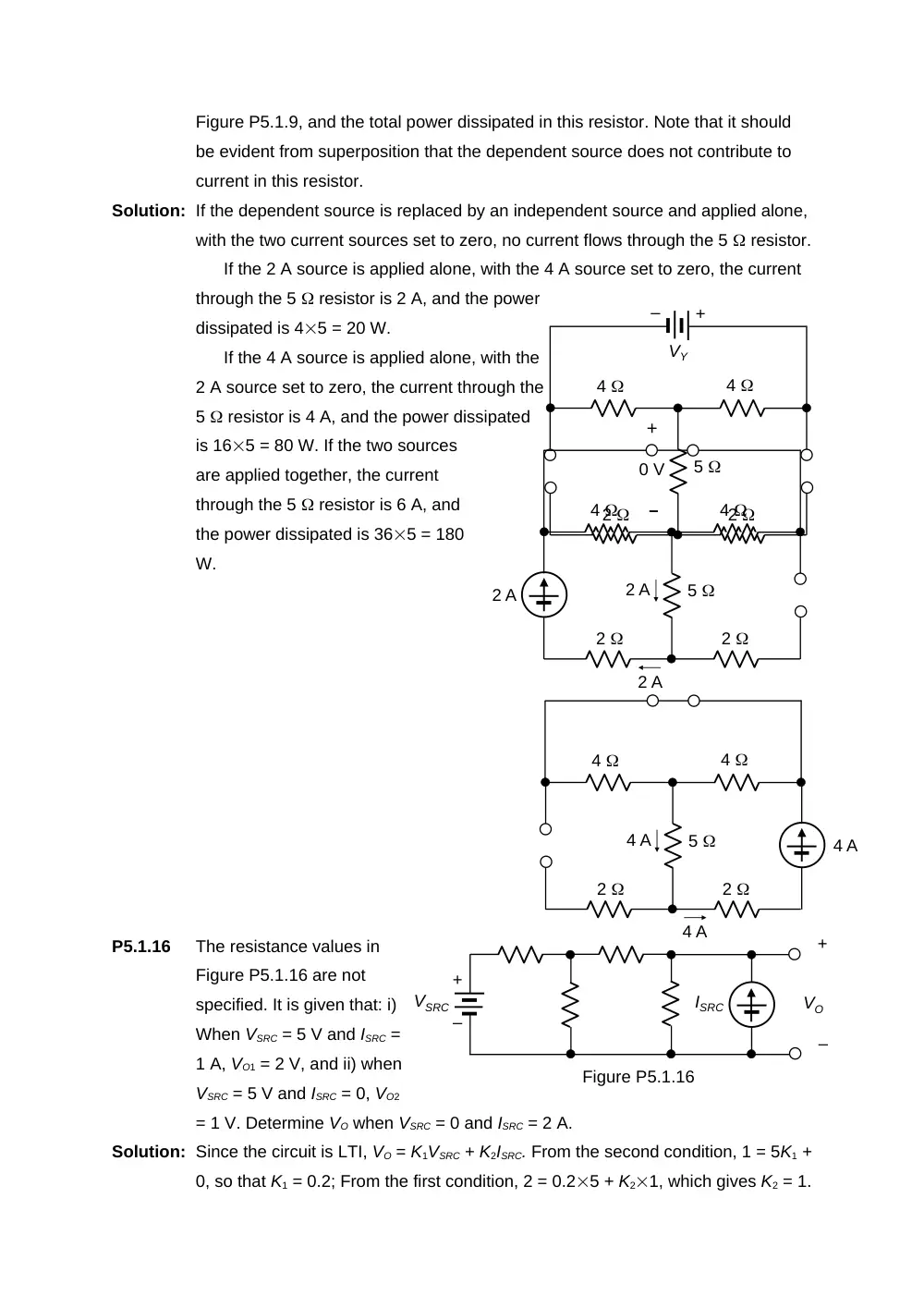
P5.1.9
Determine the power dissipated in the
5 resistor due to each source in
5
5 A
10
+
–
4
10 V
Figure P5.1.7
+
–
VO
–
+
0.2VO
IX
4
4
+
– +
3VO
5 A
10
+
–
4
10 V
IX
5 V
+
–
10
+
–
4
10 V
IX
+
–
IX
+
–
4IX
5 A
(10 + 4IX) V
5 V
(15 + 4IX)/10 A
Figure P5.1.9, and the total power dissipated in this resistor. Note that it should
be evident from superposition that the dependent source does not contribute to
current in this resistor.
Solution: If the dependent source is replaced by an independent source and applied alone,
with the two current sources set to zero, no current flows through the 5 resistor.
If the 2 A source is applied alone, with the 4 A source set to zero, the current
through the 5 resistor is 2 A, and the power
dissipated is 45 = 20 W.
If the 4 A source is applied alone, with the
2 A source set to zero, the current through the
5 resistor is 4 A, and the power dissipated
is 165 = 80 W. If the two sources
are applied together, the current
through the 5 resistor is 6 A, and
the power dissipated is 365 = 180
W.
P5.1.16
The resistance values in
Figure P5.1.16 are not
specified. It is given that: i)
When VSRC = 5 V and ISRC =
1 A, VO1 = 2 V, and ii) when
VSRC = 5 V and ISRC = 0, VO2
= 1 V. Determine VO when VSRC = 0 and ISRC = 2 A.
Solution: Since the circuit is LTI, VO = K1VSRC + K2ISRC. From the second condition, 1 = 5K1 +
0, so that K1 = 0.2; From the first condition, 2 = 0.25 + K21, which gives K2 = 1.
2
4
4
2
5
+
0 V
–
+
–
VY
4 A
2
4
4
2
5
4 A
4 A
2 A
2
4
4
2
5
2 A
2 A
+
–
+
–
VO
VSRC
ISRC
Figure P5.1.16
Hence, VO = 0.2VSRC + ISRC. Under the required conditions, VO = 0.20 + 12 = 2
V.
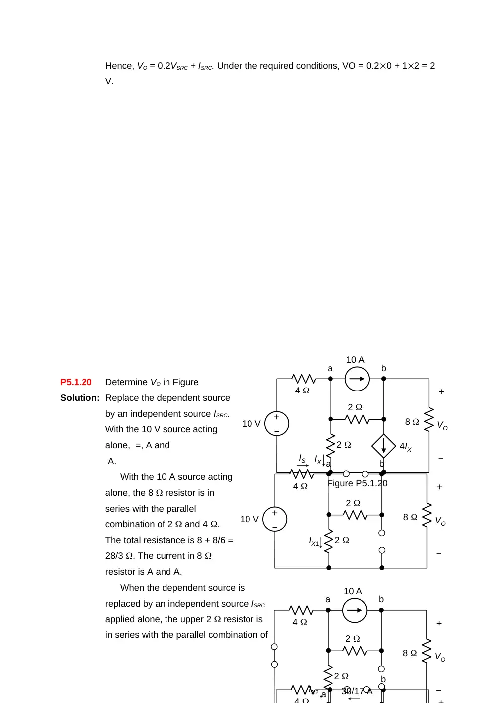
P5.1.20
Determine VO in Figure
Solution: Replace the dependent source
by an independent source ISRC.
With the 10 V source acting
alone, =, A and
A.
With the 10 A source acting
alone, the 8 resistor is in
series with the parallel
combination of 2 and 4 .
The total resistance is 8 + 8/6 =
28/3 . The current in 8
resistor is A and A.
When the dependent source is
replaced by an independent source ISRC
applied alone, the upper 2 resistor is
in series with the parallel combination of
10 V
–
+
4
10 A
8
IX
4IX
+
–
VO
2
2
a
b
Figure P5.1.20
4
+
a
b
4
10 A
8
+
–
VO
2
2
a
b
30/17 A
IX2
10 V
–
+
4
8
IS
+
–
VO
2
2
a
b
IX1
2 and 4 . The total resistance is 2 + 8/6 = 10/3 . The current in 2 resistor is
A and A.
From superposition, IX = – . Substituting ISCR = 4IX, IX = 25/17 – 20/17 –
(32/17)Ix, which gives IX = 5/49 A.
In the original circuit, Va =
2Ix = 10/49 A. The current in the
4 resistor is (10 – 10/49)/4 =
120/49 A. From KCL at the
lower node, VO/8 =120/49 –
25/49 = 95/49, or VO = 760/49 =
15.51 V.
P5.1.23
Determine VO in Figure P5.1.23.
Solution: Replace the dependent source
by an independent current source IY. With
the 10 V source acting alone, IX1 = -10/6 =
-5/3 mA.
With the 3 mA source acting alone, it
follows from current division that, IX2 =
3(2/6) = 1 mA.
With the IY source acting alone, it
follows from current division that IX3
=IY(2/6) = IY/3.
From superposition, IX = -5/3 + 1 + IY/3.
Substituting IY = 5IX, IX(1 – 5/3) = (1 – 5/3),
which gives IX = 1 mA.
From the original circuit, it follows from
KCL that the current in the lower 2 k
resistor is 8 mA, and the current in the
upper 2 k resistor is 7 mA. Hence VO =
27 + 27 = 30 V.
2 k
2 k
4 k
3 mA
+
–
10 V
+
–
VO
Ix
5Ix
Figure P5.1.23
IX
5IX
+
–
2 k
2 k
4 k
10 V
IX1
2 k
2 k
4 k
IX2
3 mA
+
–
2 k
4 k
10 V
5 mA
+
VO
7 mA
10 V
–
+
4
10 A
8
4Ix
+
–
VO
2
2
a
b
10/49 V
120/49 A
5/49 A
a
120/49 A
20/49 A
VO /8
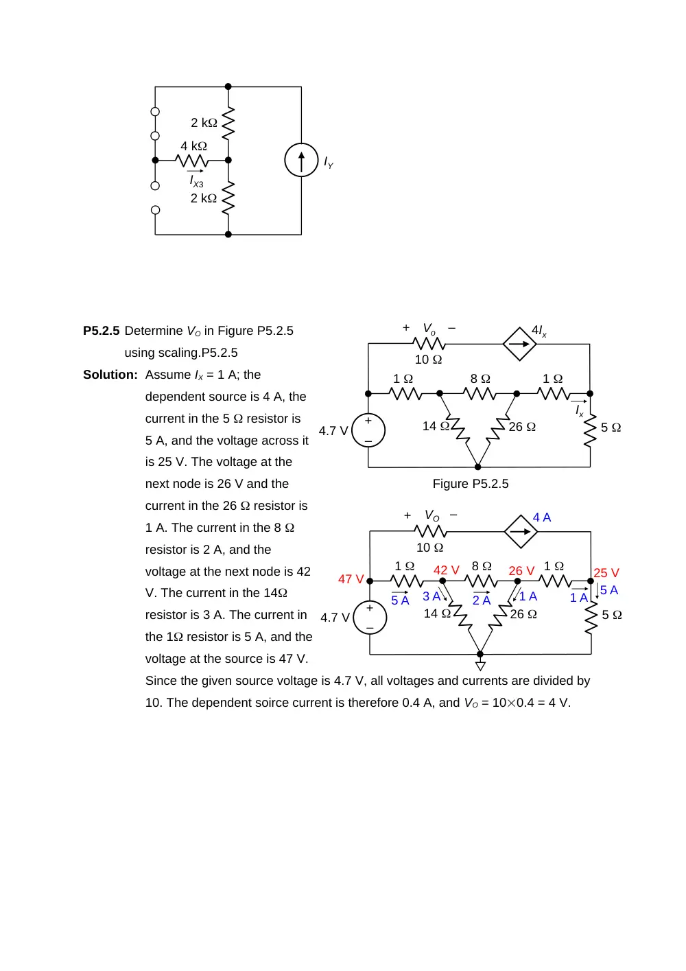
P5.2.5 Determine VO in Figure P5.2.5
using scaling.P5.2.5
Solution: Assume IX = 1 A; the
dependent source is 4 A, the
current in the 5 resistor is
5 A, and the voltage across it
is 25 V. The voltage at the
next node is 26 V and the
current in the 26 resistor is
1 A. The current in the 8
resistor is 2 A, and the
voltage at the next node is 42
V. The current in the 14
resistor is 3 A. The current in
the 1 resistor is 5 A, and the
voltage at the source is 47 V.
Since the given source voltage is 4.7 V, all voltages and currents are divided by
10. The dependent soirce current is therefore 0.4 A, and VO = 100.4 = 4 V.
2 k
2 k
4 k
IY
IX3
–
+
4.7 V
1
8
1
5
26
14
10
4Ix
Ix
Vo
–
+
Figure P5.2.5
–
+
4.7 V
1
8
1
5
26
14
10
4 A
1 A
VO
–
+
5 A
25 V
26 V
1 A
2 A
42 V
3 A
5 A
47 V
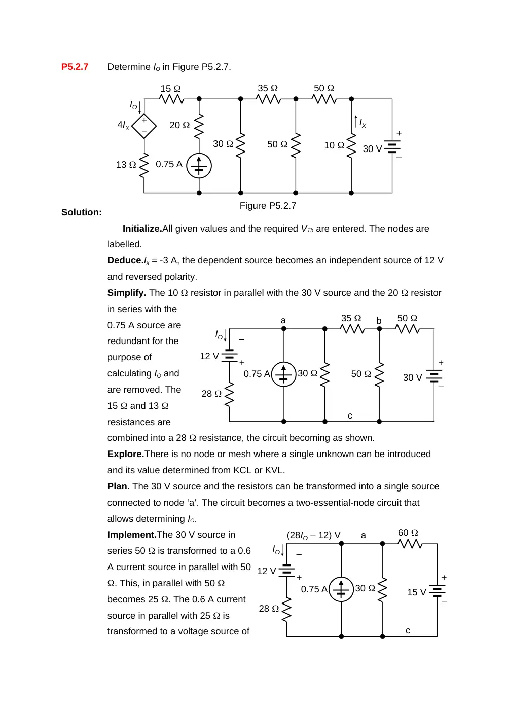
P5.2.7
Determine IO in Figure P5.2.7.
Solution:
Initialize.All given values and the required VTh are entered. The nodes are
labelled.
Deduce.Ix = -3 A, the dependent source becomes an independent source of 12 V
and reversed polarity.
Simplify. The 10 resistor in parallel with the 30 V source and the 20 resistor
in series with the
0.75 A source are
redundant for the
purpose of
calculating IO and
are removed. The
15 and 13
resistances are
combined into a 28 resistance, the circuit becoming as shown.
Explore.There is no node or mesh where a single unknown can be introduced
and its value determined from KCL or KVL.
Plan. The 30 V source and the resistors can be transformed into a single source
connected to node ‘a’. The circuit becomes a two-essential-node circuit that
allows determining IO.
Implement.The 30 V source in
series 50 is transformed to a 0.6
A current source in parallel with 50
. This, in parallel with 50
becomes 25 . The 0.6 A current
source in parallel with 25 is
transformed to a voltage source of
30
35
12 V
IO
28
0.75 A
50
50
+
–
30 V
+
–
a
b
c
20
30
35
–
+
4IX
IO
15
13
0.75 A
50
50
10
+
–
30 V
Figure P5.2.7
IX
30
12 V
IO
28
0.75 A
60
+
–
15 V
+
–
a
c
(28IO – 12) V
15 V in series with 25 . This, in series with 35 becomes 60 . The circuit
becomes as shown. Vac = 28(IO – 12) V. It follows from KCL that: ,,
, , A.
P5.2.16
Determine ISRC in Figure P5.2.16
assuming all resistances are 1 .
Solution: The circuit is symmetrical with
respect to the diagonal and could be
split into two half circuits, as shown
in the figure for one half circuit.
Combining the resistors, the
circuit becomes as shown. It follows
that the current due to one half
circuit is 7 A, so that the current due
to the complete circuit is 14 A.
+
–
1
21 V
1
6
7 A
1
2
4
1
21 V
ISRC
Figure P5.2.16
+
–
+
–
21 V
1
2
3
5
4
6
1
1
1
1
1
1