
EECE 210 Homework 6 with Solution, Fall 2013
American University of Beirut · Electric Circuits · 7 pages · with solution
More EECE 210 files
Show the text of this homework
Chapter 6 –Circuit Equations
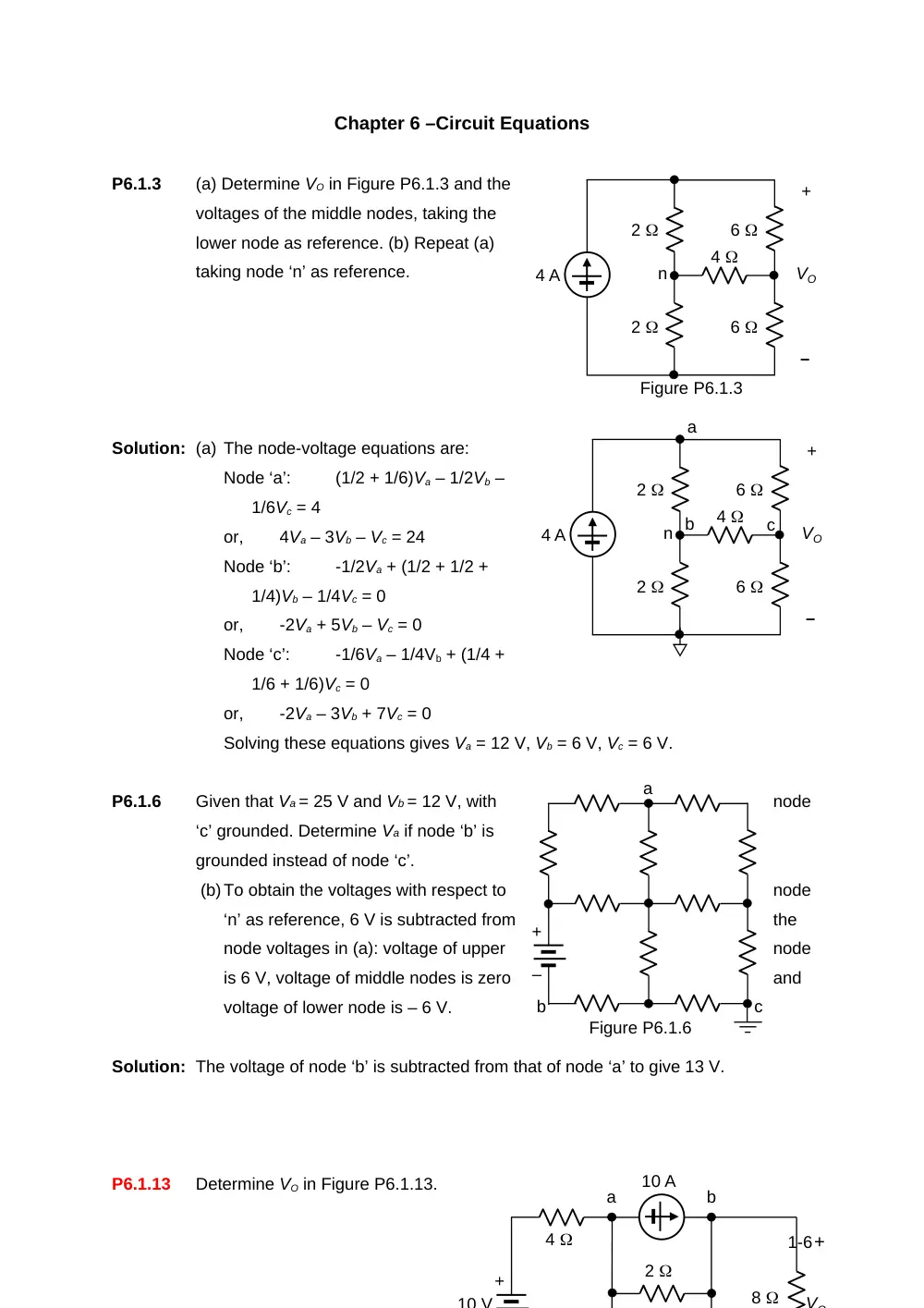
P6.1.3
(a) Determine VO in Figure P6.1.3 and the
voltages of the middle nodes, taking the
lower node as reference. (b) Repeat (a)
taking node ‘n’ as reference.
Solution: (a) The node-voltage equations are:
Node ‘a’:
(1/2 + 1/6)Va – 1/2Vb –
1/6Vc = 4
or,
4Va – 3Vb – Vc = 24
Node ‘b’:
-1/2Va + (1/2 + 1/2 +
1/4)Vb – 1/4Vc = 0
or,
-2Va + 5Vb – Vc = 0
Node ‘c’:
-1/6Va – 1/4Vb + (1/4 +
1/6 + 1/6)Vc = 0
or,
-2Va – 3Vb + 7Vc = 0
Solving these equations gives Va = 12 V, Vb = 6 V, Vc = 6 V.
P6.1.6
Given that Va = 25 V and Vb = 12 V, with
node
‘c’ grounded. Determine Va if node ‘b’ is
grounded instead of node ‘c’.
(b)To obtain the voltages with respect to
node
‘n’ as reference, 6 V is subtracted from
the
node voltages in (a): voltage of upper
node
is 6 V, voltage of middle nodes is zero
and
voltage of lower node is – 6 V.
Solution: The voltage of node ‘b’ is subtracted from that of node ‘a’ to give 13 V.
P6.1.13
Determine VO in Figure P6.1.13.
1-6
4 A
2
2
6
6
4
+
–
VO
Figure P6.1.3
n
4 A
2
2
6
6
4
+
–
VO
n
a
b
c
a
b
c
Figure P6.1.6
+
–
10 V
4
10 A
8
+
VO
2
a
b
+
Solution: Considering that a current source is connected to node ‘a’, the node voltage
equation for this node may be written as: = . This may be rearranged as: 1.25Va
– 0.5Vb = -7.5. The equation for node ‘b’ is: -0.5Va + 0.625Vb = 10 – 4Ix = 10 –
2Va, which may be rearranged as: . Solving, Va = 0.204 V and Vb = 15.51 V = VO.
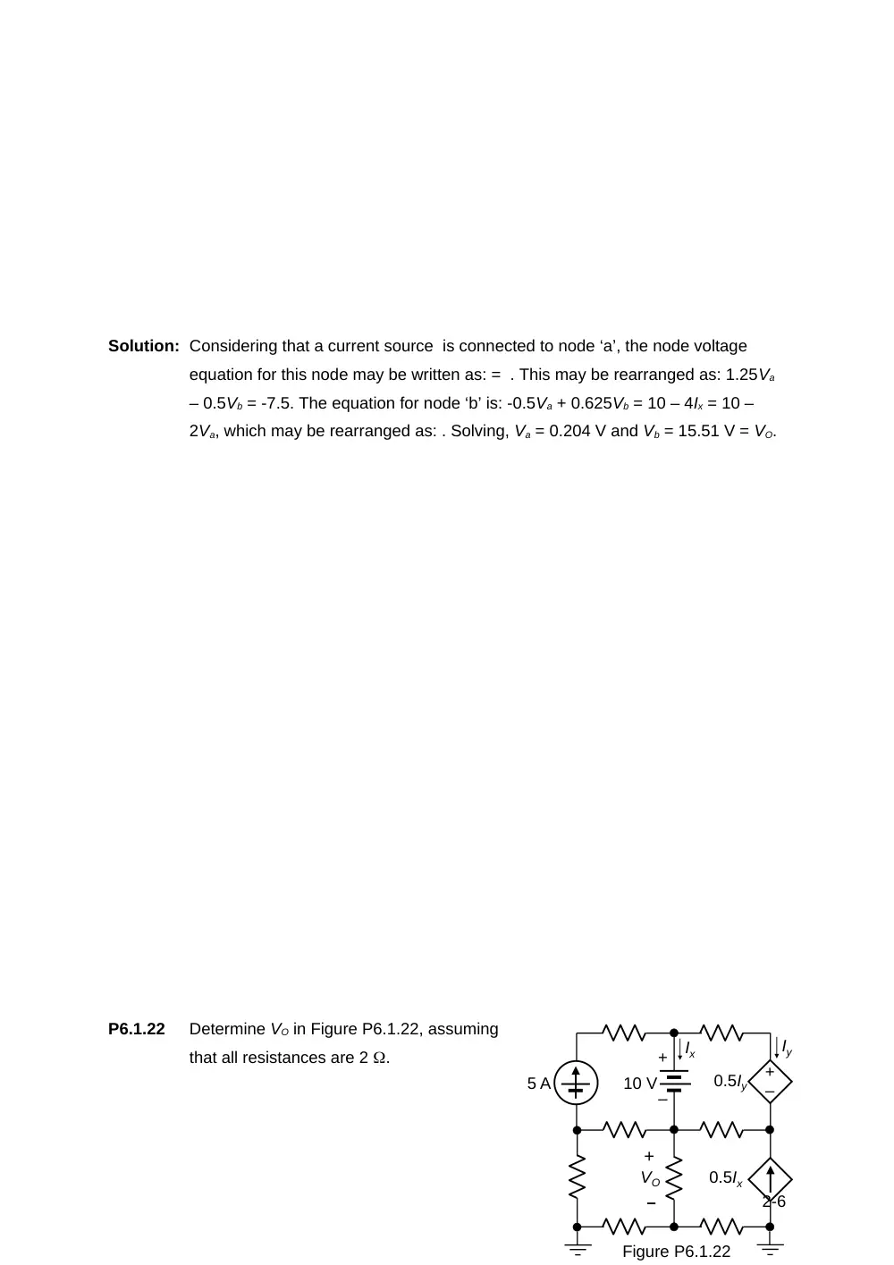
P6.1.22
Determine VO in Figure P6.1.22, assuming
that all resistances are 2 .
2-6
0.5Ix
–
+
0.5Iy
Ix
Iy
10 V
5 A
+
–
+
VO
–
Figure P6.1.22
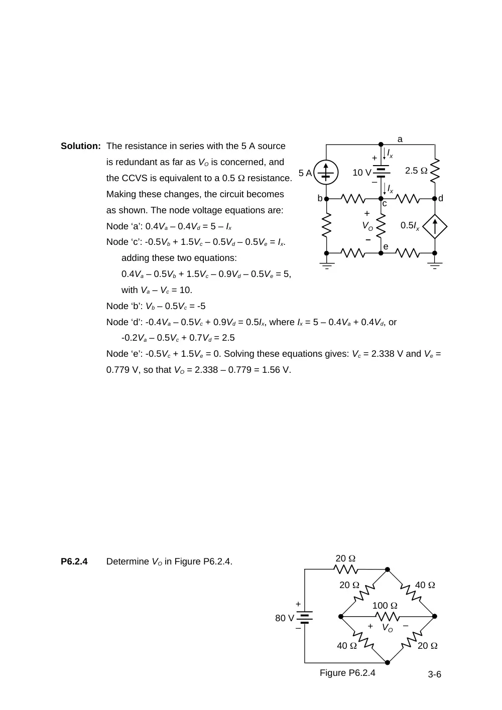
Solution: The resistance in series with the 5 A source
is redundant as far as VO is concerned, and
the CCVS is equivalent to a 0.5 resistance.
Making these changes, the circuit becomes
as shown. The node voltage equations are:
Node ‘a’: 0.4Va – 0.4Vd = 5 – Ix
Node ‘c’: -0.5Vb + 1.5Vc – 0.5Vd – 0.5Ve = Ix.
adding these two equations:
0.4Va – 0.5Vb + 1.5Vc – 0.9Vd – 0.5Ve = 5,
with Va – Vc = 10.
Node ‘b’: Vb – 0.5Vc = -5
Node ‘d’: -0.4Va – 0.5Vc + 0.9Vd = 0.5Ix, where Ix = 5 – 0.4Va + 0.4Vd, or
-0.2Va – 0.5Vc + 0.7Vd = 2.5
Node ‘e’: -0.5Vc + 1.5Ve = 0. Solving these equations gives: Vc = 2.338 V and Ve =
0.779 V, so that VO = 2.338 – 0.779 = 1.56 V.
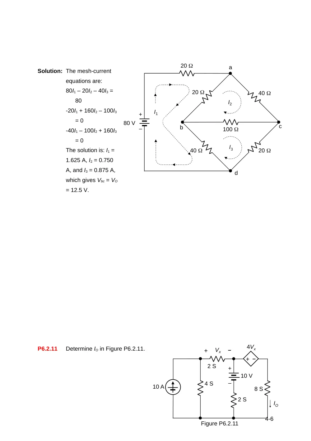
P6.2.4
Determine VO in Figure P6.2.4.
3-6
0.5Ix
Ix
10 V
5 A
+
–
+
VO
–
Ix
a
b
c
d
e
2.5
20
20
40
40
20
100
+
–
80 V
+
–
VO
Figure P6.2.4
Solution: The mesh-current
equations are:
80I1 – 20I2 – 40I3 =
80
-20I1 + 160I2 – 100I3
= 0
-40I1 – 100I2 + 160I3
= 0
The solution is: I1 =
1.625 A, I2 = 0.750
A, and I3 = 0.875 A,
which gives Vbc = VO
= 12.5 V.
P6.2.11
Determine IO in Figure P6.2.11.
4-6
20
a
b
c
d
80 V
20
I1
I2
I3
40
20
40
100
+
–
10 V
–
+
4 S
10 A
8 S
Vx
4Vx
2 S
2 S
–
+
IO
Figure P6.2.11
+
–
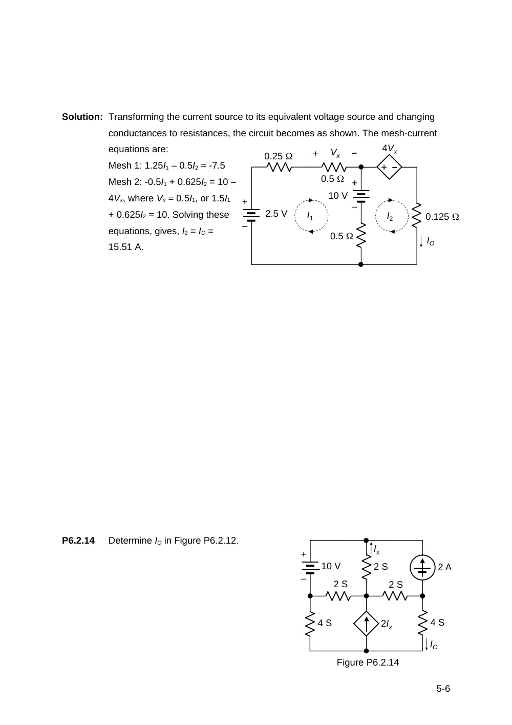
Solution: Transforming the current source to its equivalent voltage source and changing
conductances to resistances, the circuit becomes as shown. The mesh-current
equations are:
Mesh 1: 1.25I1 – 0.5I2 = -7.5
Mesh 2: -0.5I1 + 0.625I2 = 10 –
4Vx, where Vx = 0.5I1, or 1.5I1
+ 0.625I2 = 10. Solving these
equations, gives, I2 = IO =
15.51 A.
P6.2.14
Determine IO in Figure P6.2.12.
5-6
10 V
–
+
0.125
Vx
0.5
0.5
–
+
IO
+
–
0.25
+
–
2.5 V
I2
I1
4Vx
10 V
4 S
2 S
2 S
4 S
2 S
2 A
IO
2Ix
Ix
Figure P6.2.14
+
–
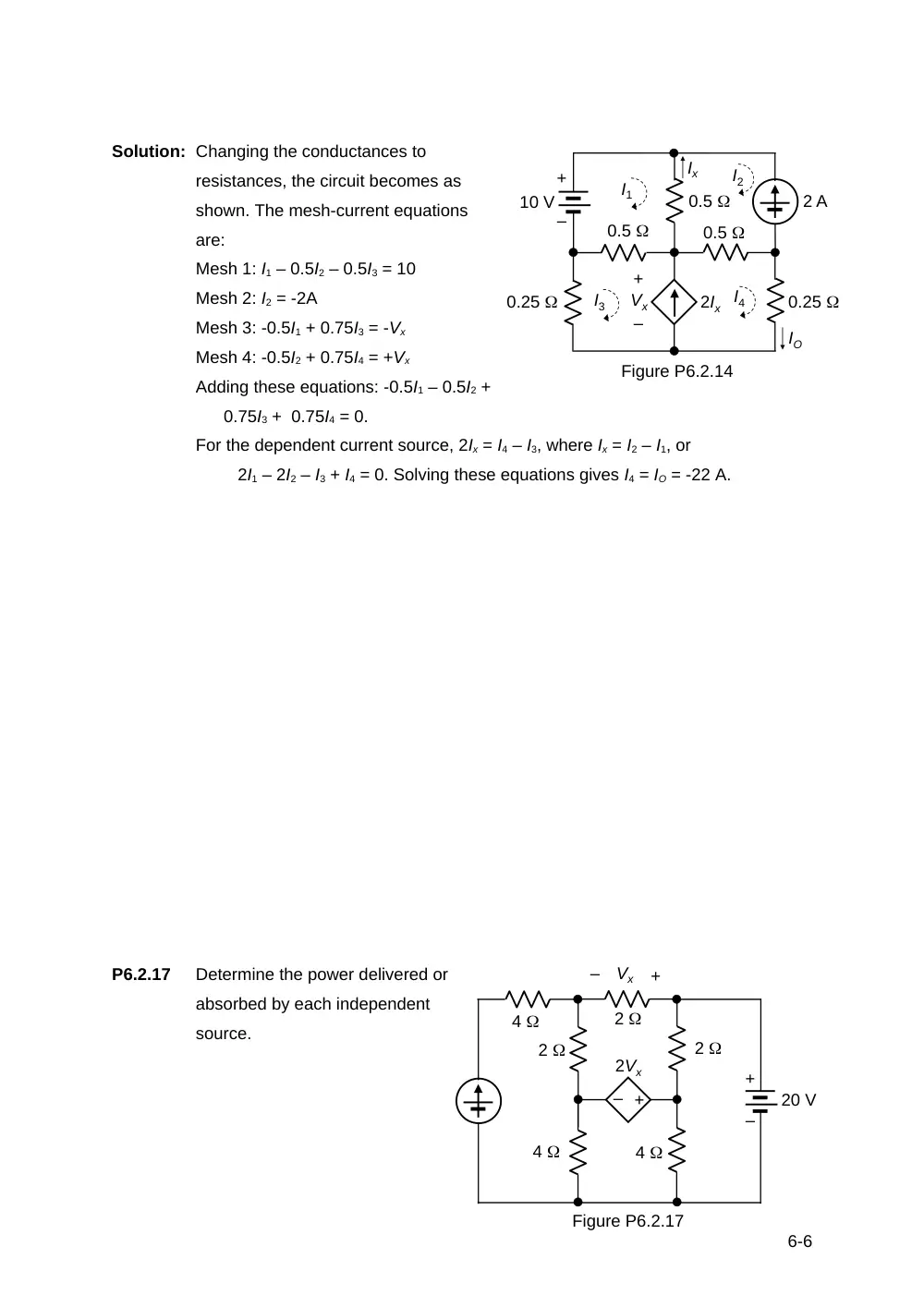
Solution: Changing the conductances to
resistances, the circuit becomes as
shown. The mesh-current equations
are:
Mesh 1: I1 – 0.5I2 – 0.5I3 = 10
Mesh 2: I2 = -2A
Mesh 3: -0.5I1 + 0.75I3 = -Vx
Mesh 4: -0.5I2 + 0.75I4 = +Vx
Adding these equations: -0.5I1 – 0.5I2 +
0.75I3 + 0.75I4 = 0.
For the dependent current source, 2Ix = I4 – I3, where Ix = I2 – I1, or
2I1 – 2I2 – I3 + I4 = 0. Solving these equations gives I4 = IO = -22 A.
P6.2.17
Determine the power delivered or
absorbed by each independent
source.
6-6
10 V
0.25
0.5
2 A
IO
2Ix
Ix
Figure P6.2.14
+
–
0.25
0.5
0.5
I1
I2
I3
I4
+
–
Vx
20 V
4
4
2
Figure P6.2.17
2
4
+
–
+
–
Vx
2Vx
+
–
2
20 V
4
10 A
4
2
2
4
+
–
+
–
2Vx
+
–
I1
I2
I3
I4
2
P6.2.17
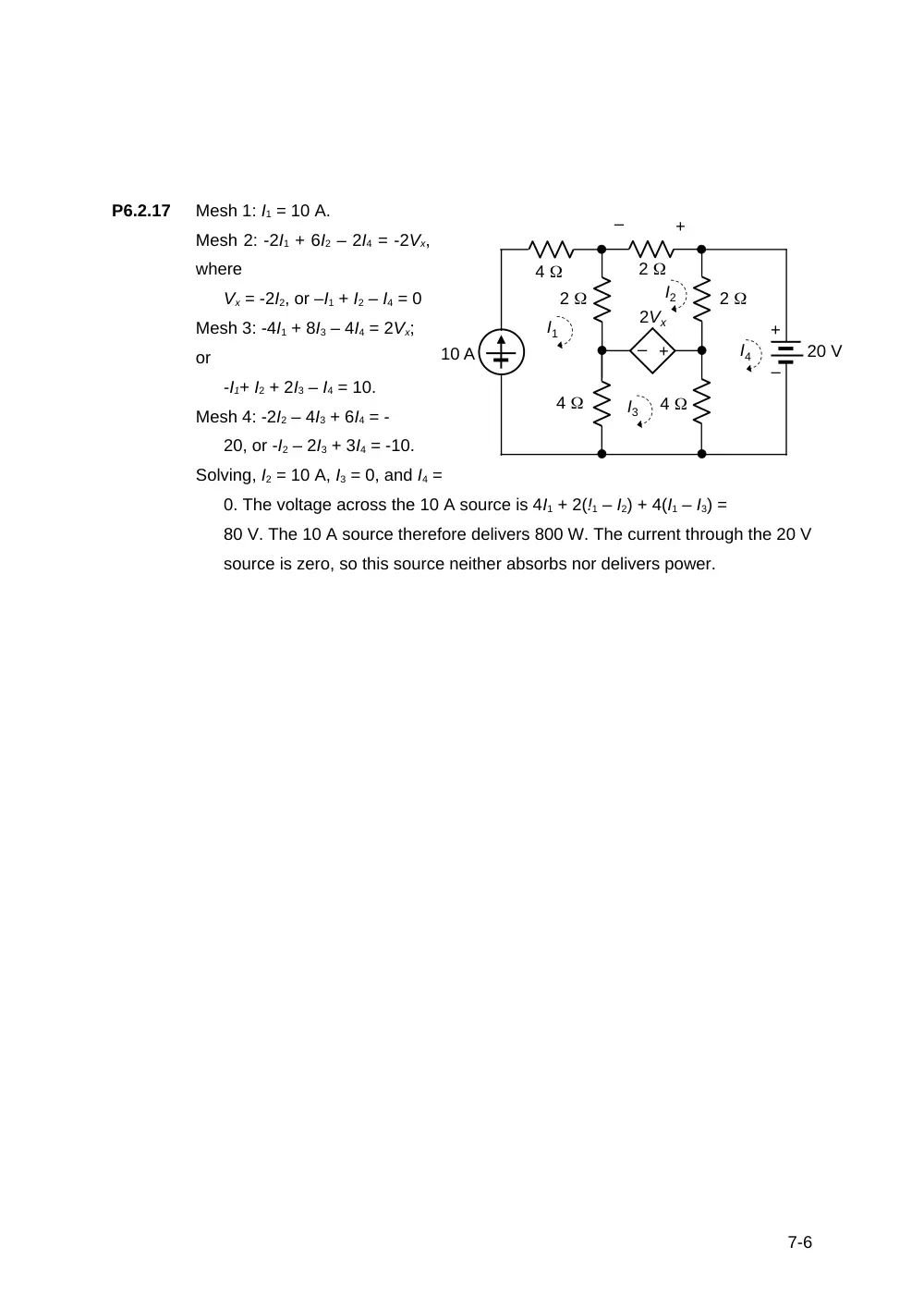
Mesh 1: I1 = 10 A.
Mesh 2: -2I1 + 6I2 – 2I4 = -2Vx,
where
Vx = -2I2, or –I1 + I2 – I4 = 0
Mesh 3: -4I1 + 8I3 – 4I4 = 2Vx;
or
-I1+ I2 + 2I3 – I4 = 10.
Mesh 4: -2I2 – 4I3 + 6I4 = -
20, or -I2 – 2I3 + 3I4 = -10.
Solving, I2 = 10 A, I3 = 0, and I4 =
0. The voltage across the 10 A source is 4I1 + 2(!1 – I2) + 4(I1 – I3) =
80 V. The 10 A source therefore delivers 800 W. The current through the 20 V
source is zero, so this source neither absorbs nor delivers power.
7-6