
EECE 210 Homework 7, Fall 2015
American University of Beirut · Electric Circuits · 6 pages · Prof. Nassir Sabah
More EECE 210 files
Show the text of this homework
1-2
Homework 7
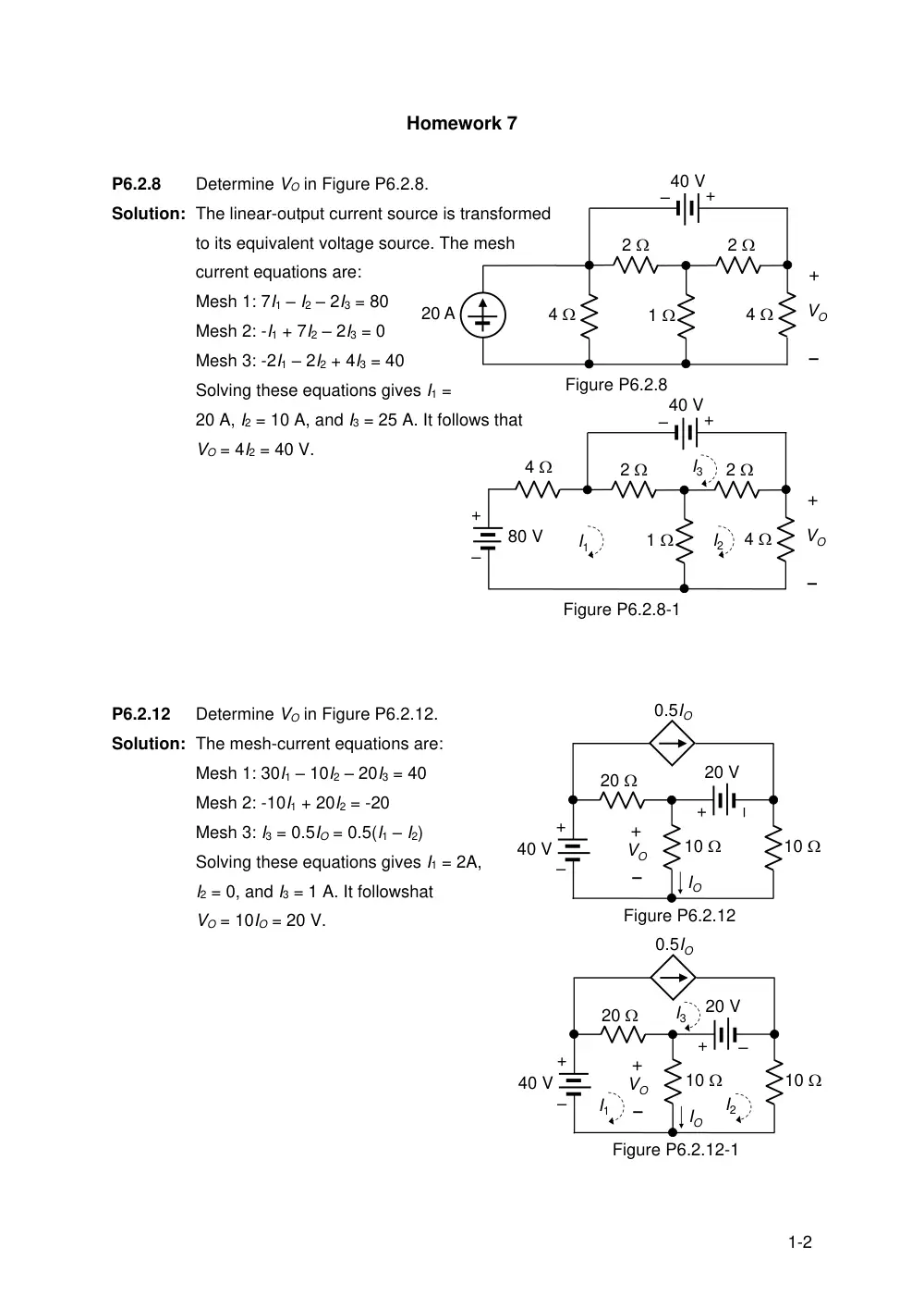
P6.2.8
Determine VO in Figure P6.2.8.
Solution: The linear-output current source is transformed
to its equivalent voltage source. The mesh
current equations are:
Mesh 1: 7I1 – I2 – 2I3 = 80
Mesh 2: -I1 + 7I2 – 2I3 = 0
Mesh 3: -2I1 – 2I2 + 4I3 = 40
Solving these equations gives I1 =
20 A, I2 = 10 A, and I3 = 25 A. It follows that
VO = 4I2 = 40 V.
P6.2.12
Determine VO in Figure P6.2.12.
Solution: The mesh-current equations are:
Mesh 1: 30I1 – 10I2 – 20I3 = 40
Mesh 2: -10I1 + 20I2 = -20
Mesh 3: I3 = 0.5IO = 0.5(I1 – I2)
Solving these equations gives I1 = 2A,
I2 = 0, and I3 = 1 A. It followshat
VO = 10IO = 20 V.
20 A
1
2
`
VO
+
–
Figure P6.2.8
4
2
4
+
–
40 V
1
2
`
VO
+
–
Figure P6.2.8-1
4
2
4
+
–
40 V
+
–
80 V
I1
I2
I3
40 V
20
IO
0.5IO
+
–
VO
10
10
20 V
+
–
+
–
Figure P6.2.12
40 V
20
IO
0.5IO
+
–
VO
10
10
20 V
+
–
+
–
Figure P6.2.12-1
I1
I2
I3
2-2
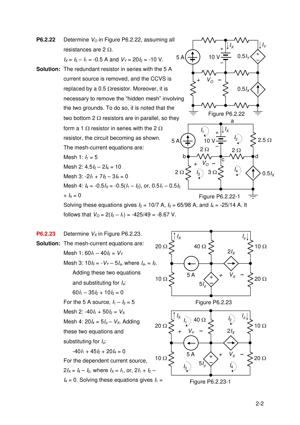
P6.2.22
Determine VO in Figure P6.2.22, assuming all
resistances are 2 .
IX = I3 – I1 = -0.5 A and VY = 20I2 = -10 V.
Solution: The redundant resistor in series with the 5 A
current source is removed, and the CCVS is
replaced by a 0.5 resistor. Moreover, it is
necessary to remove the “hidden mesh” involving
the two grounds. To do so, it is noted that the
two bottom 2 resistors are in parallel, so they
form a 1 resistor in series with the 2
resistor, the circuit becoming as shown.
The mesh-current equations are:
Mesh 1: I1 = 5
Mesh 2: 4.5I2 – 2I4 = 10
Mesh 3: -2I1 + 7I3 – 3I4 = 0
Mesh 4: I4 = -0.5IX = -0.5(I1 – I2), or, 0.5I1 – 0.5I2
+ I4 = 0
Solving these equations gives I2 = 10/7 A, I3 = 65/98 A, and I4 = -25/14 A. It
follows that VO = 2(I3 – I1) = -425/49 = -8.67 V.
P6.2.23
Determine VX in Figure P6.2.23.
Solution: The mesh-current equations are:
Mesh 1: 60I1 – 40I2 = VY
Mesh 3: 10I3 = -VY – 5I, where I, = I2.
Adding these two equations
and substituting for I:
60I1 – 35I2 + 10I3 = 0
For the 5 A source, I1 – I3 = 5
Mesh 2: -40I1 + 50I2 = VX
Mesh 4: 20I4 = 5I – VX. Adding
these two equations and
substituting for I:
-40I1 + 45I2 + 20I4 = 0
For the dependent current source,
2IX = I4 – I2, where IX = I1, or, 2I1 + I2 –
I4 = 0. Solving these equations gives I1 =
0.5IX
–
+
0.5IY
IX
IY
10 V
5 A
+
–
+
VO
–
Figure P6.2.22
0.5IX
IX
10 V
5 A
+
–
+
VO –
Figure P6.2.22-1
a
b
c
d
2.5
I1
I4
I2
2
2
2
3
I3
+
10
–
5 A
I
5I
IX
2IX
Figure P6.2.23
20
40
10
20
+
VX
–
+
10
–
5 A
I
5I
IX
2IX
Figure P6.2.23-1
20
40
10
20
+
VX
–
I1
I2
I3
I4
+
VY
–
3-2
5/7 A, I2 = 0, I3 = -30/7, and I4 = 10/7. It follows that VX = 40(I2 – I1) +10I2 = -40I1 =
-200/7 = -28.57 V.
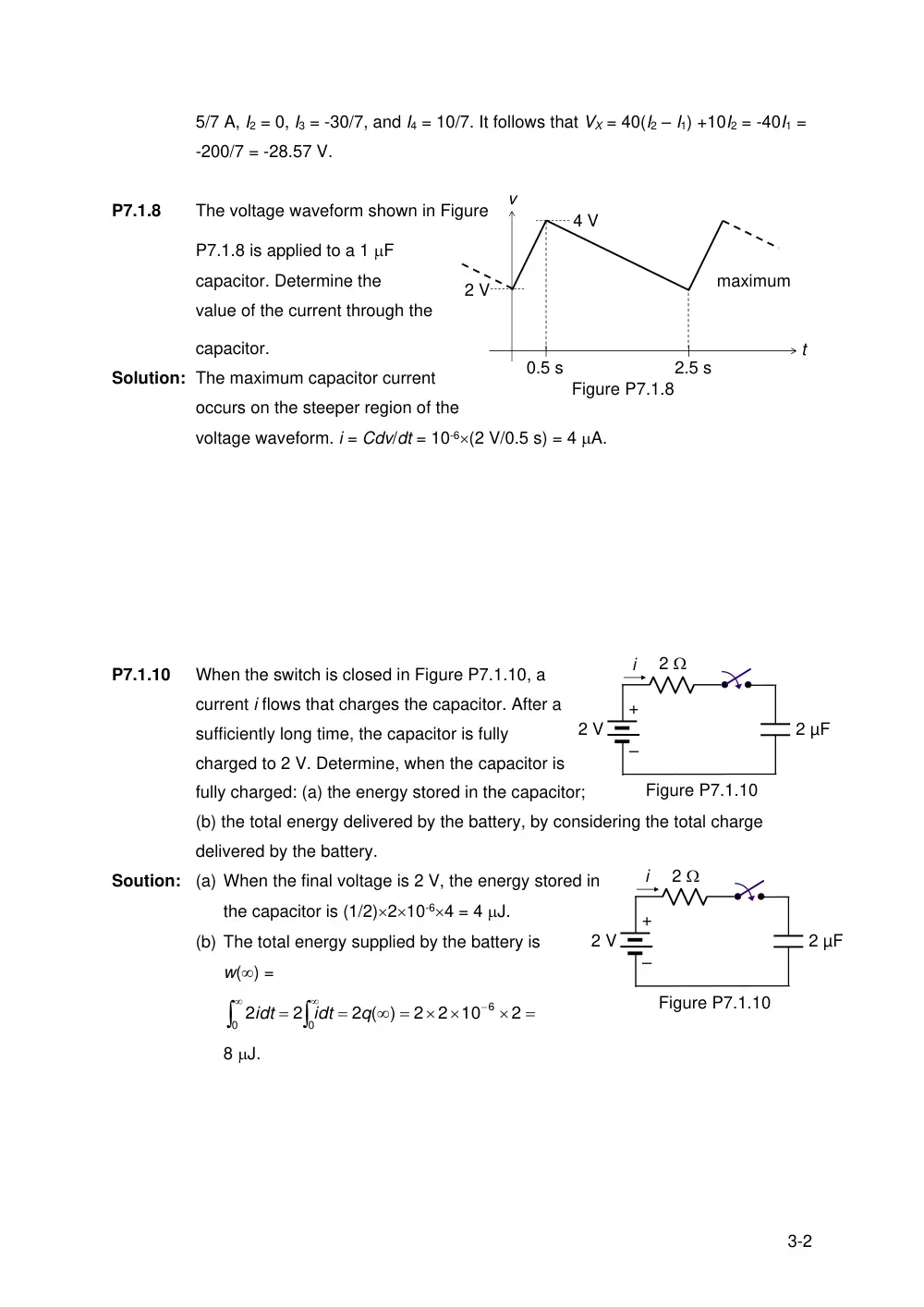
P7.1.8
The voltage waveform shown in Figure
P7.1.8 is applied to a 1 F
capacitor. Determine the
maximum
value of the current through the
capacitor.
Solution: The maximum capacitor current
occurs on the steeper region of the
voltage waveform. i = Cdv/dt = 10-6(2 V/0.5 s) = 4 A.
P7.1.10
When the switch is closed in Figure P7.1.10, a
current i flows that charges the capacitor. After a
sufficiently long time, the capacitor is fully
charged to 2 V. Determine, when the capacitor is
fully charged: (a) the energy stored in the capacitor;
(b) the total energy delivered by the battery, by considering the total charge
delivered by the battery.
Soution: (a) When the final voltage is 2 V, the energy stored in
the capacitor is (1/2)210-64 = 4 J.
(b) The total energy supplied by the battery is
w() =
0
6
0
2
2 10
2
2 ( )
2
2
q
idt
idt
8 J.
t
v
0.5 s
2.5 s
2 V
4 V
Figure P7.1.8
2 µF
2 V
+
–
2
Figure P7.1.10
i
2 µF
2 V
+
–
2
Figure P7.1.10
i
4-2
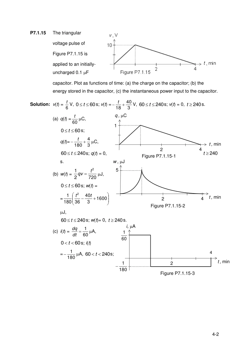
P7.1.15
The triangular
voltage pulse of
Figure P7.1.15 is
applied to an initially-
uncharged 0.1 F
capacitor. Plot as functions of time: (a) the charge on the capacitor; (b) the
energy stored in the capacitor, (c) the instantaneous power input to the capacitor.
Solution: v(t) = 6
t V,
60
0
t
s; v(t) =
3
40
18
t
V,
240
60
t
s; v(t) = 0,
t 240
s.
(a) q(t) = 60
t C,
60
0
t
s;
q(t)=
3
4
180
t
C,
240
60
t
s; q(t) = 0,
240
t
s.
(b) w(t) =
720
2
1
2t
qv
J,
60
0
t
s; w(t) =
=
1600
3
40
36
180
1
2
t
t
J,
240
60
t
s; w(t)= 0,
t 240
s.
(c) i(t) =
60
dt 1
dq
A,
60
0
t
s; i(t)
=
180
1
A,
240
60
t
s;
4
t , min
q , C
1
2
Figure P7.1.15-1
4
t , min
w , J
5
2
Figure P7.1.15-2
4
t , min
i, A
2
60
1
180
1
Figure P7.1.15-3
5-2
i(t)= 0,
t 240
s, where 60
1 A may also be expressed as 1 C/min.
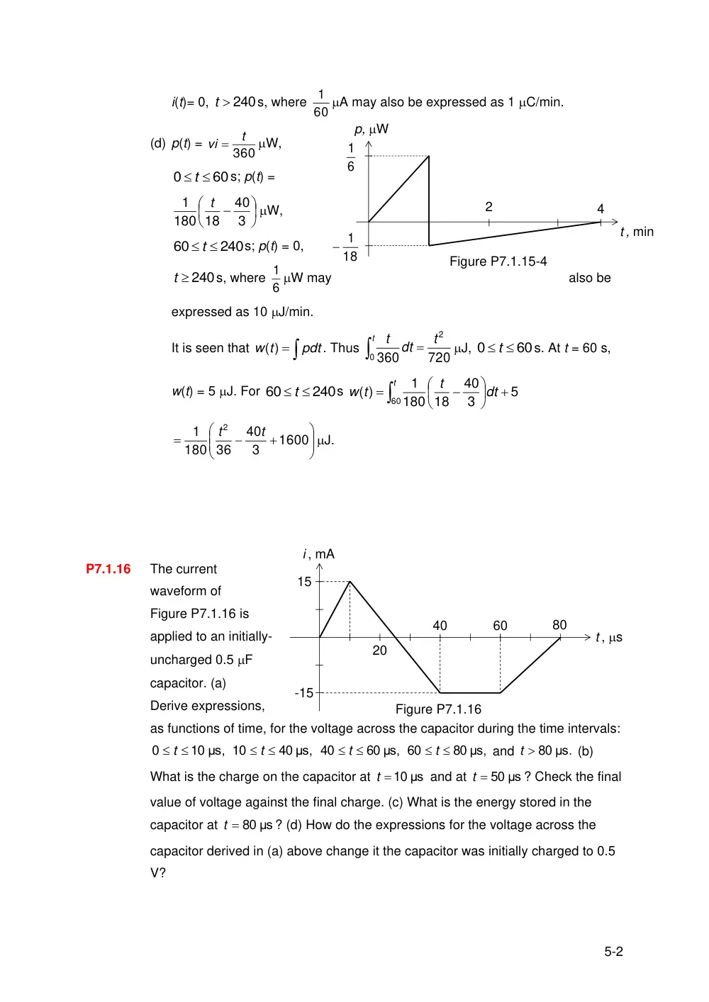
(d) p(t) =
360
t
vi
W,
60
0
t
s; p(t) =
3
40
18
180
1
t
W,
240
60
t
s; p(t) = 0,
t 240
s, where 6
1 W may
also be
expressed as 10 J/min.
It is seen that
pdt
t
w )
(
. Thus
t
t
dt
t
0
2
720
360
J,
60
0
t
s. At t = 60 s,
w(t) = 5 J. For
240
60
t
s
t
dt
t
t
w
60
5
3
40
18
180
1
( )
1600
3
40
36
180
1
2
t
t
J.
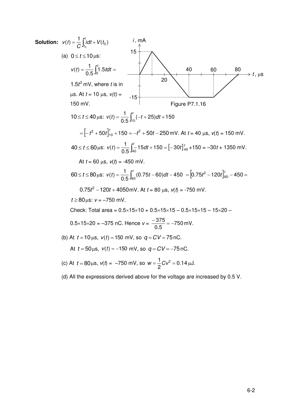
P7.1.16
The current
waveform of
Figure P7.1.16 is
applied to an initially-
uncharged 0.5 F
capacitor. (a)
Derive expressions,
as functions of time, for the voltage across the capacitor during the time intervals:
10 μs,
0
t
40 μs,
10
t
60 μs,
40
t
80 μs,
60
t
and
t 80 μs.
(b)
What is the charge on the capacitor at
t 10 μs
and at
t 50 μs
? Check the final
value of voltage against the final charge. (c) What is the energy stored in the
capacitor at
t 80 μs
? (d) How do the expressions for the voltage across the
capacitor derived in (a) above change it the capacitor was initially charged to 0.5
V?
4
t , min
p, W
2
6
1
18
1
Figure P7.1.15-4
i , mA
t , s
15
20
40
60
80
-15
Figure P7.1.16
6-2
Solution:
)
(
1
( )
0
0
V t
idt
C
t
v
t
t
(a)
10
0
t
s:
t
tdt
t
v
0 5
1.
0.5
1
( )
.5 2
1 t mV, where t is in
s. At t = 10 s, v(t) =
150 mV.
40
10
t
s:
t
dt
t
t
v
10
150
25)
(
0.5
1
( )
150
50
10
2
t t
t
250
50
2
t
t
mV. At t = 40 s, v(t) = 150 mV.
60
40
t
s:
t
dt
t
v
40
150
15
0.5
1
( )
t
t
30 40
+150 = –30t + 1350 mV.
At t = 60 s, v(t) = -450 mV.
80
60
t
s:
t
dt
t
t
v
60
450
60)
(0.75
0.5
1
( )
450
120
.75
0
60
2
t t
t
4050
120
0.75
2
t
t
mV. At t = 80 s, v(t) = -750 mV.
t 80
s: v = –750 mV.
Check: Total area = 0.51510 + 0.51515 – 0.51515 – 1520 –
0.51520 = –375 nC. Hence v =
750
0.5
375
mV.
(b) At
t 10
s,
150
( )
v t
mV, so
q CV 75
nC.
At
t 50
s,
150
( )
v t
mV, so
q CV 75
nC.
(c) At
t 80
s, v(t) = –750 mV, so
0.14
2
1
2
Cv
w
J.
(d) All the expressions derived above for the voltage are increased by 0.5 V.
i , mA
t , s
15
20
40
60
80
-15
Figure P7.1.16