
EECE 210 Homework 7 with Solution, Fall 2013
American University of Beirut · Electric Circuits · 5 pages · with solution
More EECE 210 files
Show the text of this homework
Homework 7
P7.1.2
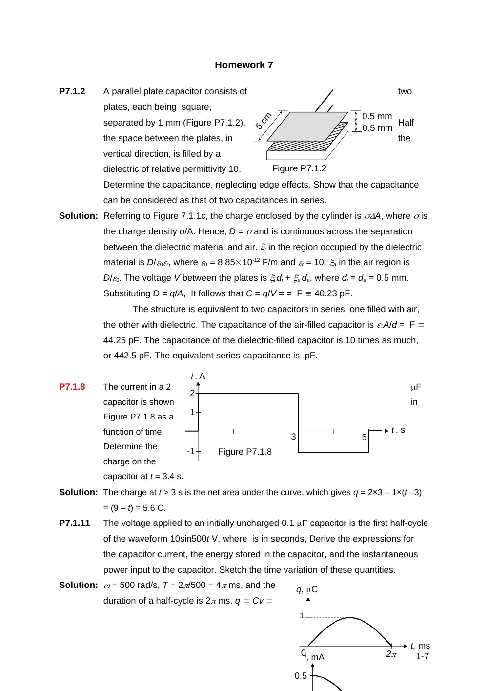
A parallel plate capacitor consists of
two
plates, each being square,
separated by 1 mm (Figure P7.1.2).
Half
the space between the plates, in
the
vertical direction, is filled by a
dielectric of relative permittivity 10.
Determine the capacitance, neglecting edge effects. Show that the capacitance
can be considered as that of two capacitances in series.
Solution: Referring to Figure 7.1.1c, the charge enclosed by the cylinder is A, where is
the charge density q/A. Hence, D = and is continuous across the separation
between the dielectric material and air. i in the region occupied by the dielectric
material is D/0r, where 0 = 8.8510-12 F/m and r = 10. a in the air region is
D/0. The voltage V between the plates is i di + a da, where di = da = 0.5 mm.
Substituting D = q/A, It follows that C = q/V = = F 40.23 pF.
The structure is equivalent to two capacitors in series, one filled with air,
the other with dielectric. The capacitance of the air-filled capacitor is 0A/d = F
44.25 pF. The capacitance of the dielectric-filled capacitor is 10 times as much,
or 442.5 pF. The equivalent series capacitance is pF.
P7.1.8
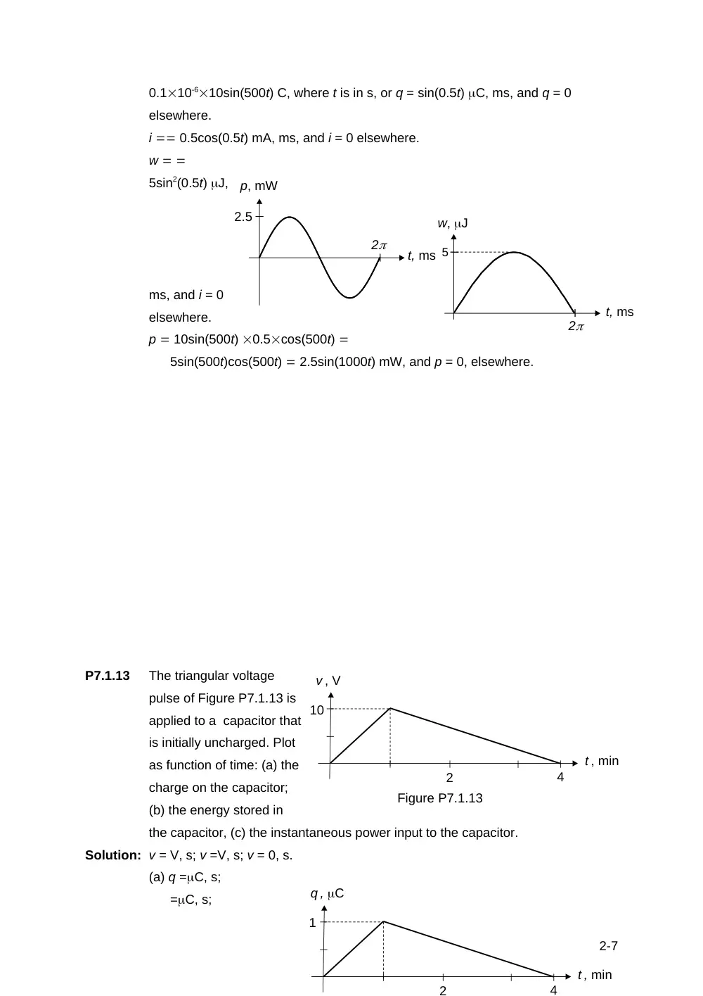
The current in a 2
F
capacitor is shown
in
Figure P7.1.8 as a
function of time.
Determine the
charge on the
capacitor at t = 3.4 s.
Solution: The charge at t > 3 s is the net area under the curve, which gives q = 2×3 – 1×(t –3)
= (9 – t) = 5.6 C.
P7.1.11
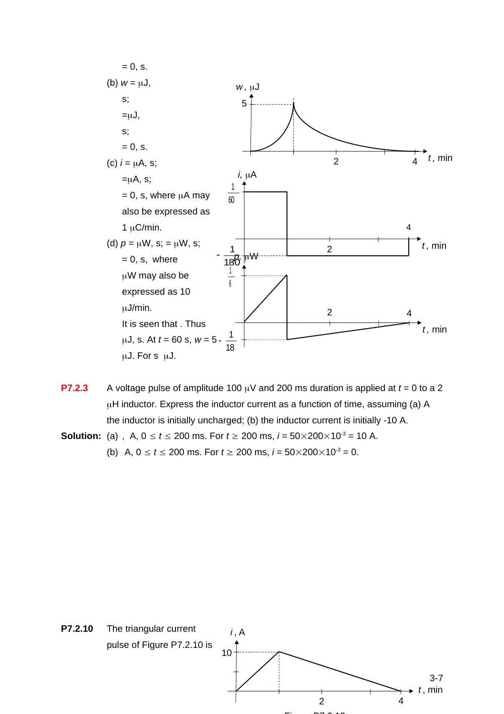
The voltage applied to an initially uncharged 0.1 F capacitor is the first half-cycle
of the waveform 10sin500t V, where is in seconds, Derive the expressions for
the capacitor current, the energy stored in the capacitor, and the instantaneous
power input to the capacitor. Sketch the time variation of these quantities.
Solution: = 500 rad/s, T = 2/500 = 4 ms, and the
duration of a half-cycle is 2 ms. q Cv
1-7
i, mA
0.5
Figure P7.1.2
0.5 mm
0.5 mm
5
t , s
i , A
1
3
Figure P7.1.8
-1
2
2
t, ms
1
q, C
0
5
w, J
2
t, ms
0.110-610sin(500t) C, where t is in s, or q = sin(0.5t) C, ms, and q = 0
elsewhere.
i 0.5cos(0.5t) mA, ms, and i = 0 elsewhere.
w
5sin2(0.5t) J,
ms, and i = 0
elsewhere.
p 10sin(500t) 0.5cos(500t)
5sin(500t)cos(500t) 2.5sin(1000t) mW, and p = 0, elsewhere.
P7.1.13
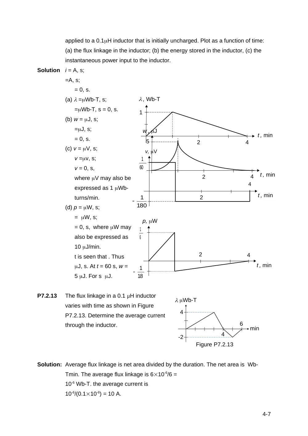
The triangular voltage
pulse of Figure P7.1.13 is
applied to a capacitor that
is initially uncharged. Plot
as function of time: (a) the
charge on the capacitor;
(b) the energy stored in
the capacitor, (c) the instantaneous power input to the capacitor.
Solution: v = V, s; v =V, s; v = 0, s.
(a) q =C, s;
=C, s;
2-7
t, ms
2
p, mW
2.5
4
t , min
q , C
1
2
4
t , min
v , V
10
2
Figure P7.1.13
4
t , min
w , J
5
2
= 0, s.
(b) w = J,
s;
=J,
s;
= 0, s.
(c) i = A, s;
=A, s;
= 0, s, where A may
also be expressed as
1 C/min.
(d) p = W, s; = W, s;
= 0, s, where
W may also be
expressed as 10
J/min.
It is seen that . Thus
J, s. At t = 60 s, w = 5
J. For s J.
P7.2.3
A voltage pulse of amplitude 100 V and 200 ms duration is applied at t = 0 to a 2
H inductor. Express the inductor current as a function of time, assuming (a) A
the inductor is initially uncharged; (b) the inductor current is initially -10 A.
Solution: (a) , A, 0 t 200 ms. For t 200 ms, i = 5020010-3 = 10 A.
(b) A, 0 t 200 ms. For t 200 ms, i = 5020010-3 = 0.
P7.2.10
The triangular current
pulse of Figure P7.2.10 is
3-7
4
t , min
i, A
2
60
1
180
1
4
t , min
p, W
2
6
1
18
1
4
t , min
i , A
10
2
Fi
P7 2 10
4
t , min
w , J
5
2
4
t , min
p, W
2
6
1
18
1
applied to a 0.1H inductor that is initially uncharged. Plot as a function of time:
(a) the flux linkage in the inductor; (b) the energy stored in the inductor, (c) the
instantaneous power input to the inductor.
Solution
i = A, s;
=A, s;
= 0, s.
(a) =Wb-T, s;
=Wb-T, s = 0, s.
(b) w = J, s;
=J, s;
= 0, s.
(c) v = V, s;
v =v, s;
v = 0, s,
where V may also be
expressed as 1 Wb-
turns/min.
(d) p = W, s;
= W, s;
= 0, s, where W may
also be expressed as
10 J/min.
t is seen that . Thus
J, s. At t = 60 s, w =
5 J. For s J.
P7.2.13
The flux linkage in a 0.1 μH inductor
varies with time as shown in Figure
P7.2.13. Determine the average current
through the inductor.
Solution: Average flux linkage is net area divided by the duration. The net area is Wb-
Tmin. The average flux linkage is 610-6/6 =
10-6 Wb-T. the average current is
10-6/(0.110-6) = 10 A.
4-7
4
t , min
2
60
1
180
1
v, V
4
t , min
, Wb-T
1
2
min
Wb-T
4
4
6
-2
Figure P7.2.13
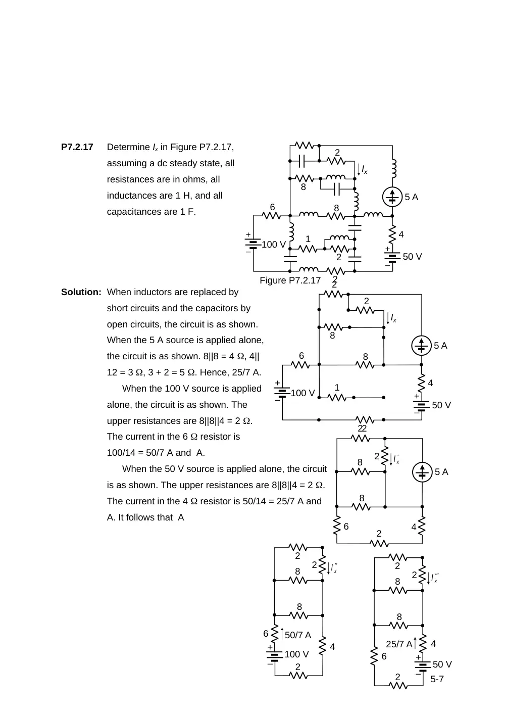
P7.2.17
Determine Ix in Figure P7.2.17,
assuming a dc steady state, all
resistances are in ohms, all
inductances are 1 H, and all
capacitances are 1 F.
Solution: When inductors are replaced by
short circuits and the capacitors by
open circuits, the circuit is as shown.
When the 5 A source is applied alone,
the circuit is as shown. 8||8 = 4 , 4||
12 = 3 , 3 + 2 = 5 . Hence, 25/7 A.
When the 100 V source is applied
alone, the circuit is as shown. The
upper resistances are 8||8||4 = 2 .
The current in the 6 resistor is
100/14 = 50/7 A and A.
When the 50 V source is applied alone, the circuit
is as shown. The upper resistances are 8||8||4 = 2 .
The current in the 4 resistor is 50/14 = 25/7 A and
A. It follows that A
5-7
6
2
8
8
2
2
4
xI
+
–
100 V
50/7 A
6
2
8
8
2
2
4
5 A
xI
4
2
8
8
2
2
6
xI
+
–
50 V
25/7 A
+
–
+
–
100 V
6
1
2
2
8
8
2
4
Figure P7.2.17
50 V
5 A
Ix
+
–
+
–
100 V
6
1
2
8
8
2
2
4
50 V
5 A
Ix