
EECE 210 Homework 7 with Solution, Fall 2014
American University of Beirut · Electric Circuits · 5 pages · with solution

More EECE 210 files
Show the text of this homework
Homework 7
P7.1.3
A parallel plate capacitor consists of two
plates, each being square, separated by
1
mm (Figure P7.1.3), as in the preceding
problem. Half the space between the
plates, in the horizontal direction, is filled
by
a dielectric of relative permittivity 10.
Determine the capacitance, neglecting
edge effects. Show that the capacitance
can
be considered as that of two capacitances in parallel.
Solution: The electric field is the same throughout the space between the plates and is
V/d. In the air-filled region Da = 0 and is equal to the charge density on the
plates. The charge on the plates in this region is 0Aa,where Aa = 52.5 cm2. In
the dielectric-filled region, Di = 0r and is equal to the charge density on the
plates. The charge on the plates in this region is 0rAi,where Ai = 52.5 cm2.
The total charge on the plates is q = 0(Aa + rAi) = 0V(Aa + rAi)/d. The
capacitance is F = 121.7 pF.
The structure is equivalent to two capacitors in parallel, one filled with air,
the other with dielectric. The capacitance of the air-filled capacitor is 0Aa/d = F
11.06 pF. The capacitance of the dielectric-filled capacitor is 10 times as much,
or 110.63 pF. The equivalent parallel capacitance is (11.06 + 110.63) = 121.7 pF.
P7.1.7
The current in a 1 μF
capacitor is shown in
1
2.5 cm
Figure P7.1.3
1 mm
4
t , ms
i , mA
10
2
Figure P7.1.7
5
w, J
2
t, ms
Figure P7.1.7 as a function of time. Determine the total energy stored in the
capacitor.
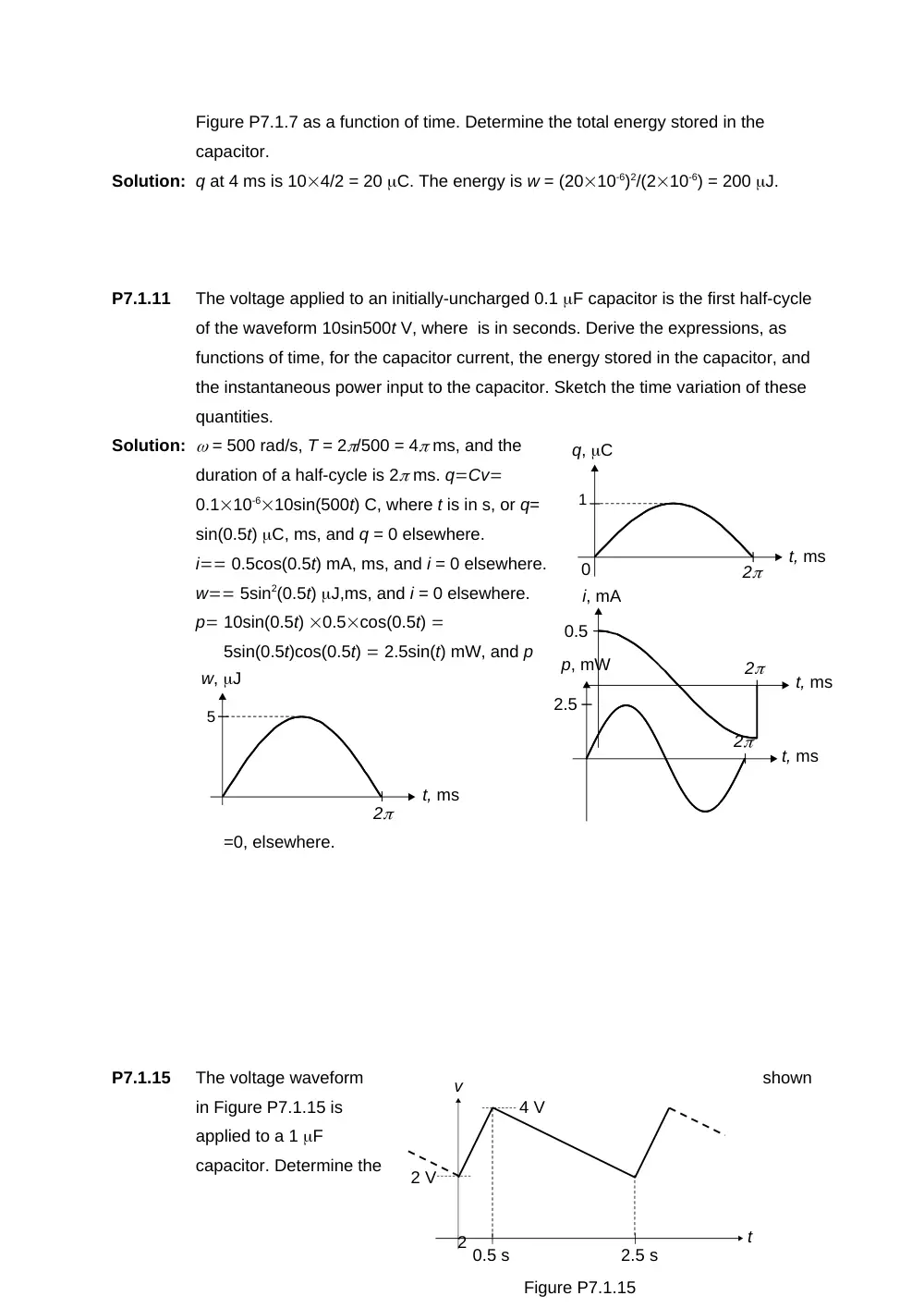
Solution: q at 4 ms is 104/2 = 20 C. The energy is w = (2010-6)2/(210-6) = 200 J.
P7.1.11
The voltage applied to an initially-uncharged 0.1 F capacitor is the first half-cycle
of the waveform 10sin500t V, where is in seconds. Derive the expressions, as
functions of time, for the capacitor current, the energy stored in the capacitor, and
the instantaneous power input to the capacitor. Sketch the time variation of these
quantities.
Solution: = 500 rad/s, T = 2/500 = 4 ms, and the
duration of a half-cycle is 2 ms. qCv
0.110-610sin(500t) C, where t is in s, or q=
sin(0.5t) C, ms, and q = 0 elsewhere.
i 0.5cos(0.5t) mA, ms, and i = 0 elsewhere.
w 5sin2(0.5t) J,ms, and i = 0 elsewhere.
p 10sin(0.5t) 0.5cos(0.5t)
5sin(0.5t)cos(0.5t) 2.5sin(t) mW, and p
=0, elsewhere.
P7.1.15
The voltage waveform
shown
in Figure P7.1.15 is
applied to a 1 F
capacitor. Determine the
2
2
t, ms
1
q, C
0
t, ms
2
i, mA
0.5
t, ms
2
p, mW
2.5
t
v
0.5 s
2.5 s
2 V
4 V
Figure P7.1.15
4
t , min
w , J
5
2
4
t , min
p, W
2
6
1
18
1
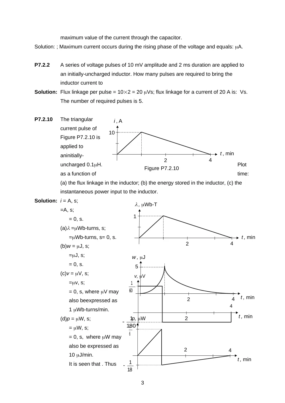
maximum value of the current through the capacitor.
Solution: ; Maximum current occurs during the rising phase of the voltage and equals: A.
P7.2.2
A series of voltage pulses of 10 mV amplitude and 2 ms duration are applied to
an initially-uncharged inductor. How many pulses are required to bring the
inductor current to
Solution: Flux linkage per pulse = 102 = 20 Vs; flux linkage for a current of 20 A is: Vs.
The number of required pulses is 5.
P7.2.10
The triangular
current pulse of
Figure P7.2.10 is
applied to
aninitially-
uncharged 0.1H.
Plot
as a function of
time:
(a) the flux linkage in the inductor; (b) the energy stored in the inductor, (c) the
instantaneous power input to the inductor.
Solution: i = A, s;
=A, s;
= 0, s.
(a) =Wb-turns, s;
=Wb-turns, s= 0, s.
(b)w = J, s;
=J, s;
= 0, s.
(c)v = V, s;
=v, s;
= 0, s, where V may
also beexpressed as
1 Wb-turns/min.
(d)p = W, s;
= W, s;
= 0, s, where W may
also be expressed as
10 J/min.
It is seen that . Thus
3
4
t , min
2
60
1
180
1
v, V
4
t , min
i , A
10
2
Figure P7.2.10
4
t , min
, Wb-T
1
2
J, s. At t = 60 s, w = 5 J. For s J.
P7.2.13
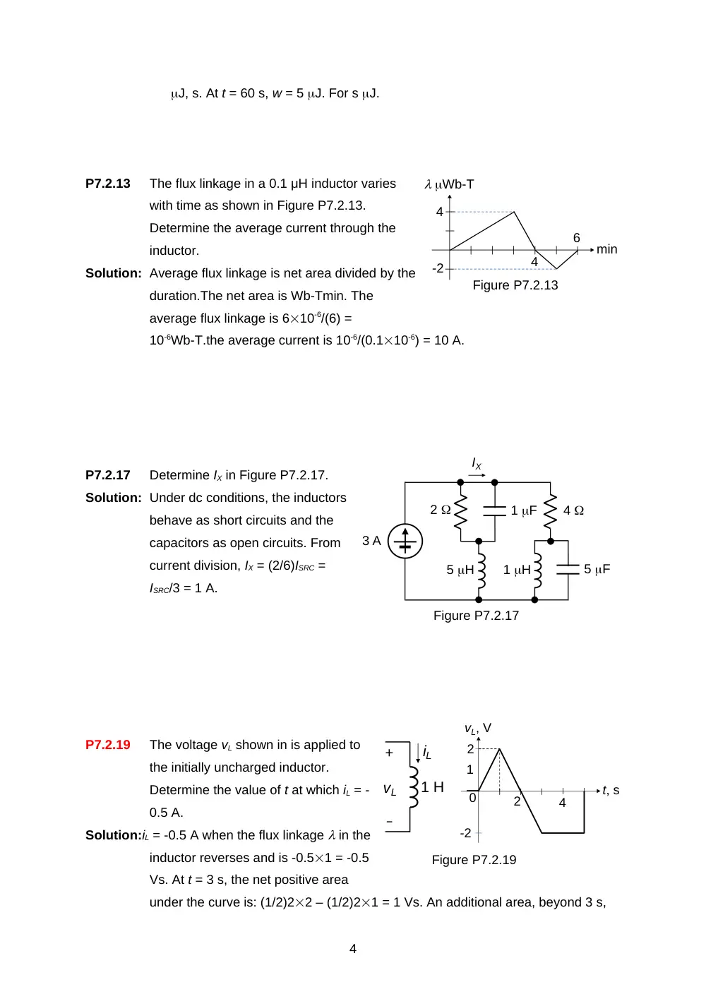
The flux linkage in a 0.1 μH inductor varies
with time as shown in Figure P7.2.13.
Determine the average current through the
inductor.
Solution: Average flux linkage is net area divided by the
duration.The net area is Wb-Tmin. The
average flux linkage is 610-6/(6) =
10-6Wb-T.the average current is 10-6/(0.110-6) = 10 A.
P7.2.17
Determine IX in Figure P7.2.17.
Solution: Under dc conditions, the inductors
behave as short circuits and the
capacitors as open circuits. From
current division, IX = (2/6)ISRC =
ISRC/3 = 1 A.
P7.2.19
The voltage vL shown in is applied to
the initially uncharged inductor.
Determine the value of t at which iL = -
0.5 A.
Solution:iL = -0.5 A when the flux linkage in the
inductor reverses and is -0.51 = -0.5
Vs. At t = 3 s, the net positive area
under the curve is: (1/2)22 – (1/2)21 = 1 Vs. An additional area, beyond 3 s,
4
Figure P7.2.17
ISRC
Ix
2
4
1 F
5 F
1 H
5 H
3 A
IX
min
Wb-T
4
4
6
-2
Figure P7.2.13
+
–
vL
iL
1 H
vL, V
1
2
0
t, s
-2
2
4
Figure P7.2.19
of -1.5is required to make the total area -0.5 Vs. This occurs at t = 3 + 0.5/2 =
3.75 s.
5