
EECE 210 Homework 9, Fall 2015
American University of Beirut · Electric Circuits · 5 pages · Prof. Nassir Sabah


More EECE 210 files
Show the text of this homework
1-2
Homework 9
P8.1.6
Given A = 3 + j5, B = 10 – j8, and C = j12. Determine the phasors resulting from
the following operations: (a) ABC; (b) (AB)/C; (c) (A/B)C; and (d) A/B/C.
Express the result in rectangular and polar forms.
Solution: A = 3 + j5 = 5.8359.04
B = 10 – j8 = 12.81-38.66
C = j12 = 1290
(a) ABC = 896.1110.4 -312 + j840
(b) (AB)/C = 6.22-69.62 2.17 – j5.83
(c) (A/B)C = 5.46187.7 -5.41 – j0.73
(d) A/B/C = 0.0376 + j0.0051, 0.03797.696
P8.2.20
Determine ZTh looking into terminals
‘ab’ in Figure P8.2.20.
Solution: The admittance of L in parallel
with C -j/20 + j/10 = j0.05 S. It
follows that VX = 2VXj0.05, so
that VX = 0. Hence, ZTh = 1/j0.05 = -j20 .
P8.3.12
Determine VX in Figure P8.3.12.
Solution: The j2 in series with -j2 is a
short circuit. It follows that VX =
2
2
2
20 60
j
)
10 60 (1
j
10 2 15
V.
j20
Figure P8.2.20
2VX
a
b
-j10
j20
-j10
+
VX
–
2
Figure P8.3.12
+
VX
–
j2
j2
-j2
j5
-j5
2060 V
10
5
j10
–
+
2-2
P8.3.26
Determine iC(t) in Figure
P8.2.26, assuming vSRC(t) =
sin(1000t + 30) V.
Solution: jL = j10000.1 = j100 ; -j/C = -j/(100010-5) =
-j100 ; it follows that the parallel impedance of L
and C is infinite. The circuit reduces to that
shown in the frequency domain. From KVL, VSRC
= 5IX + 5(8 + 1)IX = 50IX; IX = VSRC/50 mA; VC =
1(5IX) = VSRC/10 V; IC = jCVC = jVC/100 A jVSRC mA =
j130 = 1120 mA. Hence, iC(t) = sin(1000t + 120) mA.
1 k
10 F
0.1 H
–
+
8 k
5 k
4iX
vSRC
iC
iX
Figure P8.3.26
1 k
–
+
8 k
5 k
4IX
VSRC
IX
VC
+
_
5IX
P8.3.26-1
3-2
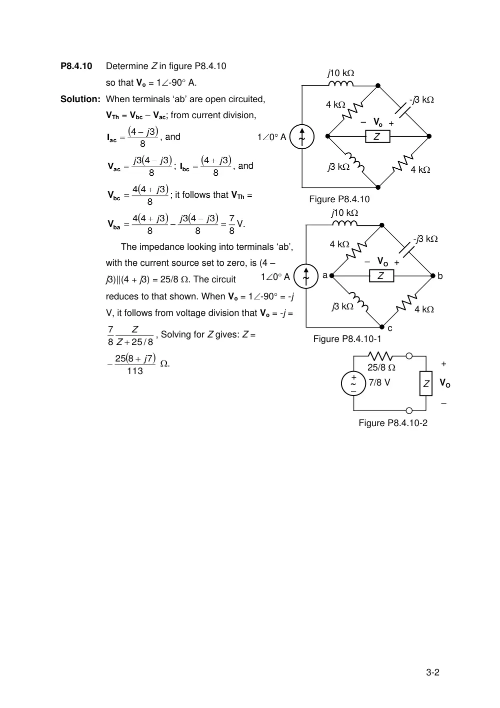
P8.4.10
Determine Z in figure P8.4.10
so that Vo = 1-90 A.
Solution: When terminals ‘ab’ are open circuited,
VTh = Vbc – Vac; from current division,
8
3
4
j
Iac
, and
8
3
3 4
j
j
Vac
;
8
3
4
j
Ibc
, and
8
3
4 4
j
Vbc
; it follows that VTh =
8
7
8
3
4
3
8
3
4 4
j
j
j
Vba
V.
The impedance looking into terminals ‘ab’,
with the current source set to zero, is (4 –
j3)||(4 + j3) = 25/8 . The circuit
reduces to that shown. When Vo = 1-90 = -j
V, it follows from voltage division that Vo = -j =
25/ 8
8
7
Z
Z
, Solving for Z gives: Z =
113
7
25 8
j
.
–
+
25/8
7/8 V
+
–
VO
Figure P8.4.10-2
Z
-j3 k
j10 k
4 k
10 A
Figure P8.4.10
j3 k
4 k
Z
+
– Vo
-j3 k
j10 k
4 k
10 A
b
Figure P8.4.10-1
j3 k
4 k
Z
+
– VO
a
c
4-2
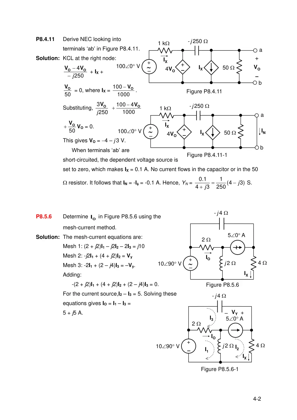
P8.4.11
Derive NEC looking into
terminals ‘ab’ in Figure P8.4.11.
Solution: KCL at the right node:
250
4
j
O
O
V
V
+ IX +
50
VO
= 0, where IX =
1000
100
VO
.
Substituting, 250
3
j
VO
1000
4
100
VO
50
VO
VO = 0.
This gives VO = 4 – j 3 V.
When terminals ‘ab’ are
short-circuited, the dependent voltage source is
set to zero, which makes IX = 0.1 A. No current flows in the capacitor or in the 50
resistor. It follows that IN = -I = -0.1 A. Hence, YN =
3)
(4
250
1
3
4
0.1
j
j
S.
P8.5.6
Determine O
I
in Figure P8.5.6 using the
mesh-current method.
Solution: The mesh-current equations are:
Mesh 1: (2 + j2)I1 – j2I2 – 2I3 = j10
Mesh 2: -j2I1 + (4 + j2)I2 = Vy
Mesh 3: -2I1 + (2 – j4)I3 = –Vy.
Adding:
-(2 + j2)I1 + (4 + j2)I2 + (2 – j4)I3 = 0.
For the current source,I2 – I3 = 5. Solving these
equations gives IO = I1 – I3 =
5 + j5 A.
- j 250
50
1000 V
1 k
IX
–
+
4VO
IX
+
–
VO
a
b
Figure P8.4.11
–
+
- j 250
50
1000 V
1 k
IX
–
+
4VO
IX
a
b
–
+
IN
Figure P8.4.11-1
1090 V
2
j 2
4
50 A
IO
- j 4
IX
Figure P8.5.6
–
+
–
+
1090 V
2
j 2
4
50 A
IO
- j 4
IX
I1
I2
I3
+
– VY
Figure P8.5.6-1
5-2
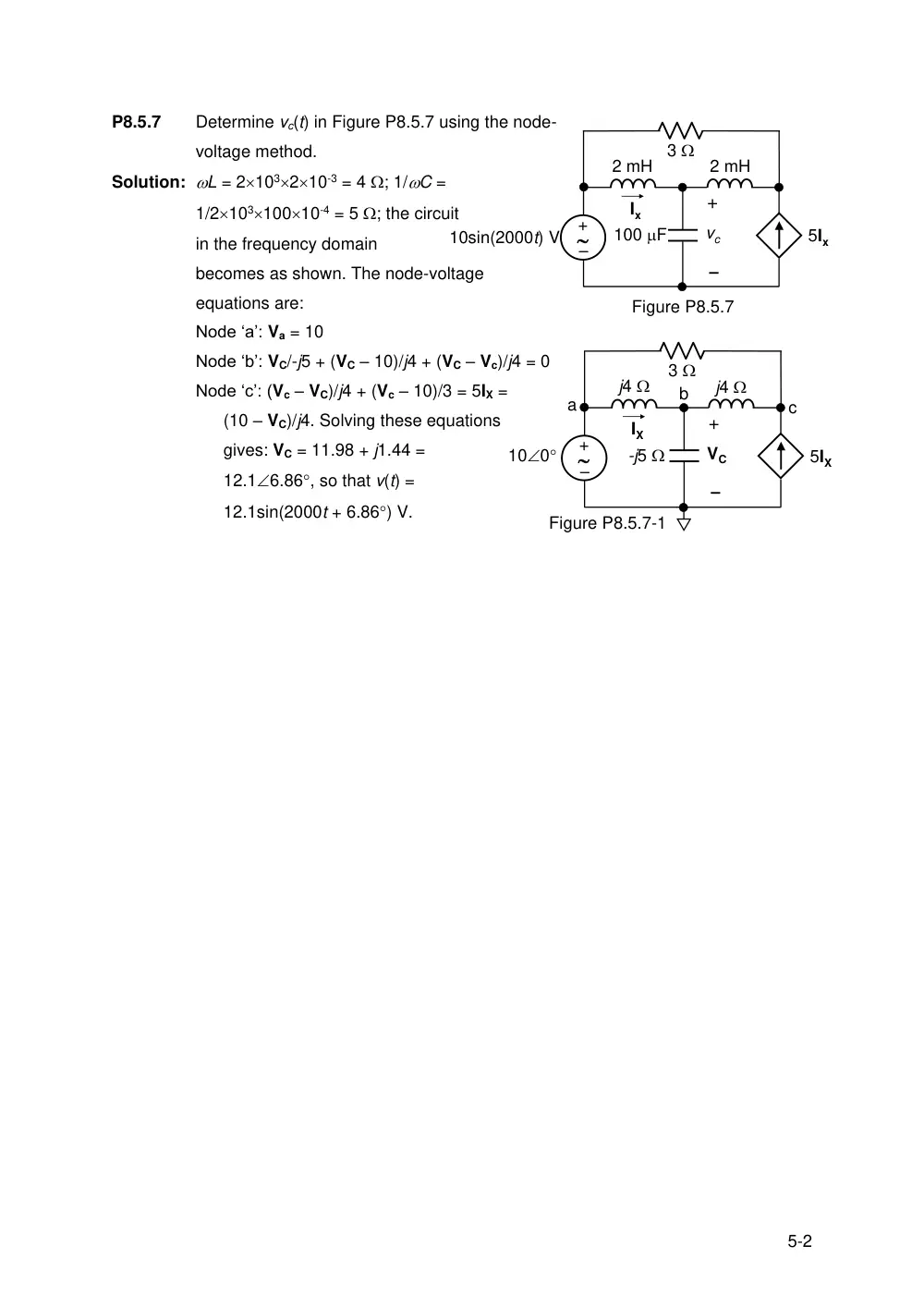
P8.5.7
Determine vc(t) in Figure P8.5.7 using the node-
voltage method.
Solution: L = 2103210-3 = 4 ; 1/C =
1/210310010-4 = 5 ; the circuit
in the frequency domain
becomes as shown. The node-voltage
equations are:
Node ‘a’: Va = 10
Node ‘b’: VC/-j5 + (VC – 10)/j4 + (VC – Vc)/j4 = 0
Node ‘c’: (Vc – VC)/j4 + (Vc – 10)/3 = 5IX =
(10 – VC)/j4. Solving these equations
gives: VC = 11.98 + j1.44 =
12.16.86, so that v(t) =
12.1sin(2000t + 6.86) V.
10sin(2000t) V
2 mH
100 F
Ix
Figure P8.5.7
2 mH
3
5Ix
+
vc
–
–
+
100
j4
IX
Figure P8.5.7-1
3
5IX
+
VC
–
–
+
j4
-j5
a
b
c