
EECE 210 Homework 9 with Solution, Fall 2013
American University of Beirut · Electric Circuits · 5 pages · with solution

More EECE 210 files
Show the text of this homework
0.5 F
+
–
vx
5cos(10t) V
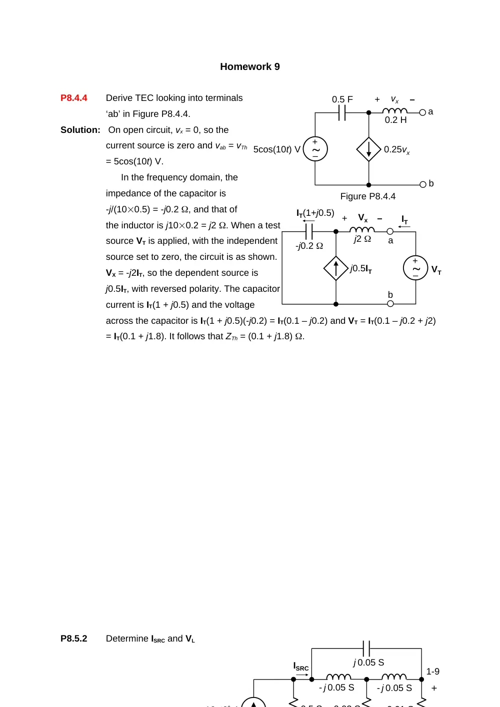
Figure P8.4.4
0.2 H
0.25vx
a
b
–
+
0 01 S
- j 0.05 S
0 02 S
ISRC
0 5 S
- j 0.05 S
j 0.05 S
+
10 0 A
Homework 9
P8.4.4
Derive TEC looking into terminals
‘ab’ in Figure P8.4.4.
Solution: On open circuit, vx = 0, so the
current source is zero and vab = vTh
= 5cos(10t) V.
In the frequency domain, the
impedance of the capacitor is
-j/(100.5) = -j0.2 , and that of
the inductor is j100.2 = j2 . When a test
source VT is applied, with the independent
source set to zero, the circuit is as shown.
VX = -j2IT, so the dependent source is
j0.5IT, with reversed polarity. The capacitor
current is IT(1 + j0.5) and the voltage
across the capacitor is IT(1 + j0.5)(-j0.2) = IT(0.1 – j0.2) and VT = IT(0.1 – j0.2 + j2)
= IT(0.1 + j1.8). It follows that ZTh = (0.1 + j1.8) .
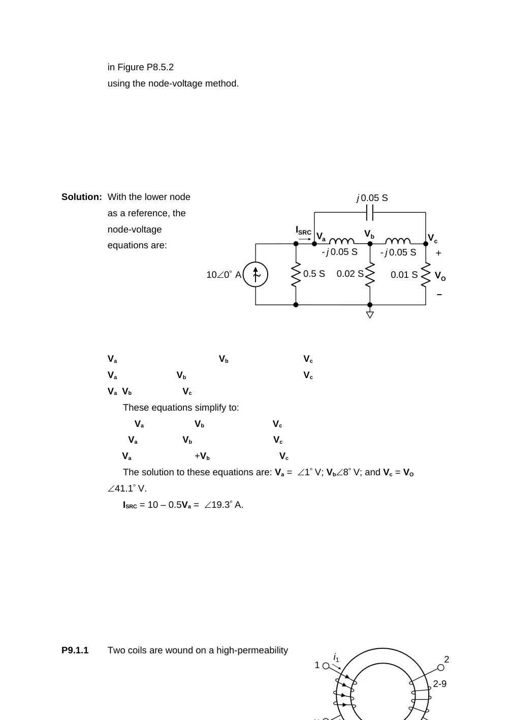
P8.5.2
Determine ISRC and VL
1-9
-j0.2
+
–
Vx
j0.5IT
a
b
j2
VT
IT
IT(1+j0.5)
–
+
0.01 S
- j 0.05 S
0.02 S
ISRC
0.5 S
- j 0.05 S
j 0.05 S
+
VO
–
100 A
Va
Vb
Vc
in Figure P8.5.2
using the node-voltage method.
Solution: With the lower node
as a reference, the
node-voltage
equations are:
Va
Vb
Vc
Va
Vb
Vc
Va Vb
Vc
These equations simplify to:
Va
Vb
Vc
Va
Vb
Vc
Va
+Vb
Vc
The solution to these equations are: Va = 1 V; Vb8 V; and Vc = VO
41.1 V.
ISRC = 10 – 0.5Va = 19.3 A.
P9.1.1
Two coils are wound on a high-permeability
2-9
i1
1
2
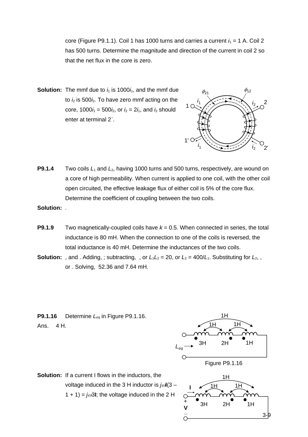
core (Figure P9.1.1). Coil 1 has 1000 turns and carries a current i1 = 1 A. Coil 2
has 500 turns. Determine the magnitude and direction of the current in coil 2 so
that the net flux in the core is zero.
Solution: The mmf due to i1 is 1000i1, and the mmf due
to i2 is 500i2. To have zero mmf acting on the
core, 1000i1 = 500i2, or i2 = 2i1, and i2 should
enter at terminal 2.
P9.1.4
Two coils L1 and L2, having 1000 turns and 500 turns, respectively, are wound on
a core of high permeability. When current is applied to one coil, with the other coil
open circuited, the effective leakage flux of either coil is 5% of the core flux.
Determine the coefficient of coupling between the two coils.
Solution: .
P9.1.9
Two magnetically-coupled coils have k = 0.5. When connected in series, the total
inductance is 80 mH. When the connection to one of the coils is reversed, the
total inductance is 40 mH. Determine the inductances of the two coils.
Solution: , and . Adding, ; subtracting, , or L1L2 = 20, or L2 = 400/L1. Substituting for L2, ,
or . Solving, 52.36 and 7.64 mH.
P9.1.16
Determine Leq in Figure P9.1.16.
Ans.
4 H.
Solution: If a current I flows in the inductors, the
voltage induced in the 3 H inductor is jI(3 –
1 + 1) = j3I; the voltage induced in the 2 H
3-9
1H
1H
1H
1H
2H
3H
Leq
Figure P9.1.16
i1
i2
i1
1'
1
21
i2
2'
2
12
1H
1H
1H
1H
2H
3H
I
+
_V
inductor is jI(2 – 1 – 1) = 0; the voltage induced in the 1 H inductor is jI(1 – 1 +
1) = jI; V = j3I + jI = j4I. It follows that Leq = 4 H.
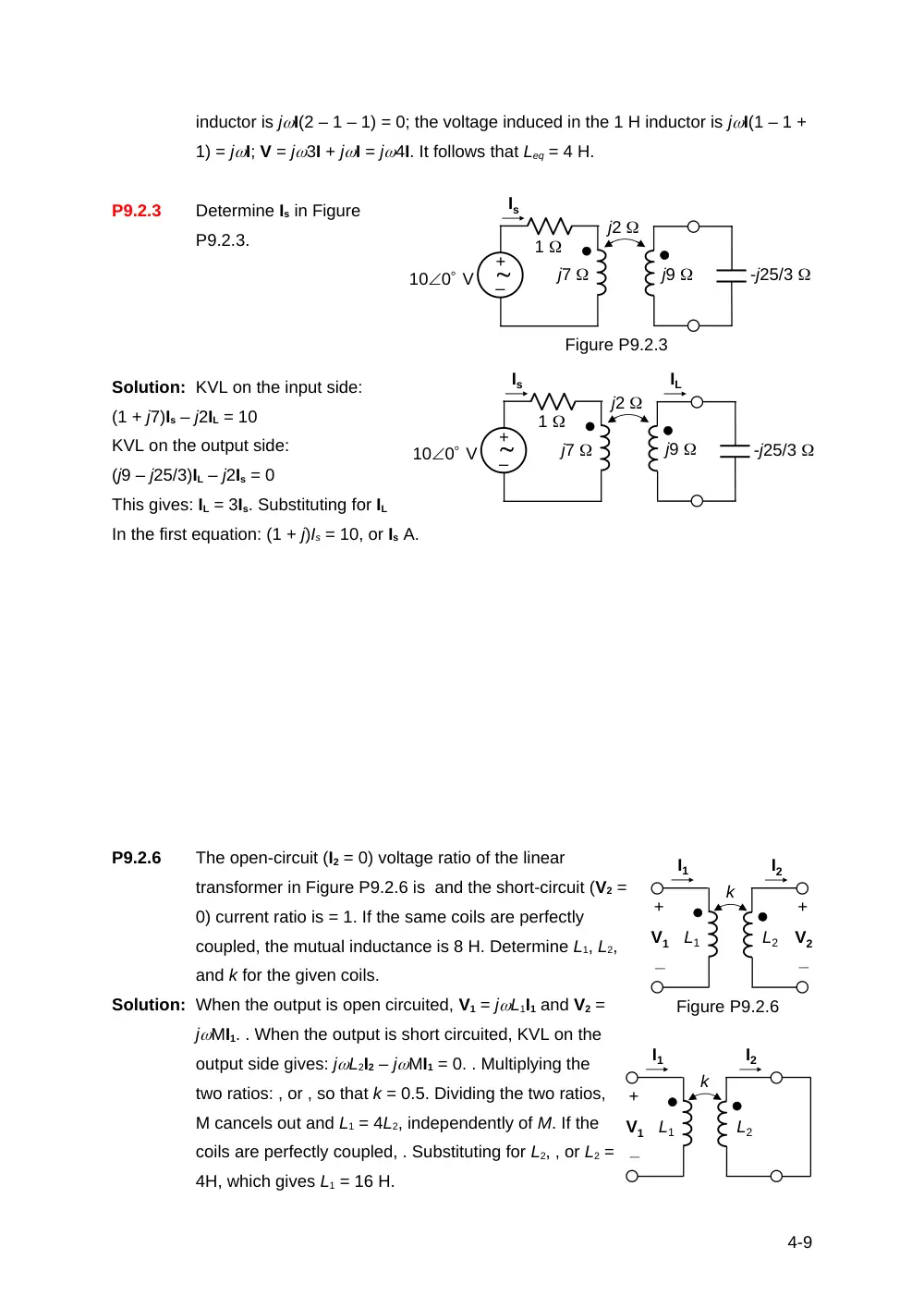
P9.2.3
Determine Is in Figure
P9.2.3.
Solution: KVL on the input side:
(1 + j7)Is – j2IL = 10
KVL on the output side:
(j9 – j25/3)IL – j2Is = 0
This gives: IL = 3Is. Substituting for IL
In the first equation: (1 + j)Is = 10, or Is A.
P9.2.6
The open-circuit (I2 = 0) voltage ratio of the linear
transformer in Figure P9.2.6 is and the short-circuit (V2 =
0) current ratio is = 1. If the same coils are perfectly
coupled, the mutual inductance is 8 H. Determine L1, L2,
and k for the given coils.
Solution: When the output is open circuited, V1 = jL1I1 and V2 =
jMI1. . When the output is short circuited, KVL on the
output side gives: jL2I2 – jMI1 = 0. . Multiplying the
two ratios: , or , so that k = 0.5. Dividing the two ratios,
M cancels out and L1 = 4L2, independently of M. If the
coils are perfectly coupled, . Substituting for L2, , or L2 =
4H, which gives L1 = 16 H.
4-9
j9
j7
Figure P9.2.3
-j25/3
j2
1
100 V
Is
–
+
j9
j7
-j25/3
j2
1
100 V
Is
–
+
IL
Figure P9.2.6
L2
L1
k
+
_
V2
+
_
V1
I1
I2
L2
L1
k
+
_
V1
I1
I2
5-9