
EECE 210 Homework 9 with Solution, Fall 2014
American University of Beirut · Electric Circuits · 5 pages · with solution
More EECE 210 files
Show the text of this homework
–
+
IX
2IX
5
3
j 2
- j
+
–
VY
2VY
20 V
190 A
Figure P8.3.21
–
+
IX
j 2
j A
b
j + I
1 – jIX
Homework 9
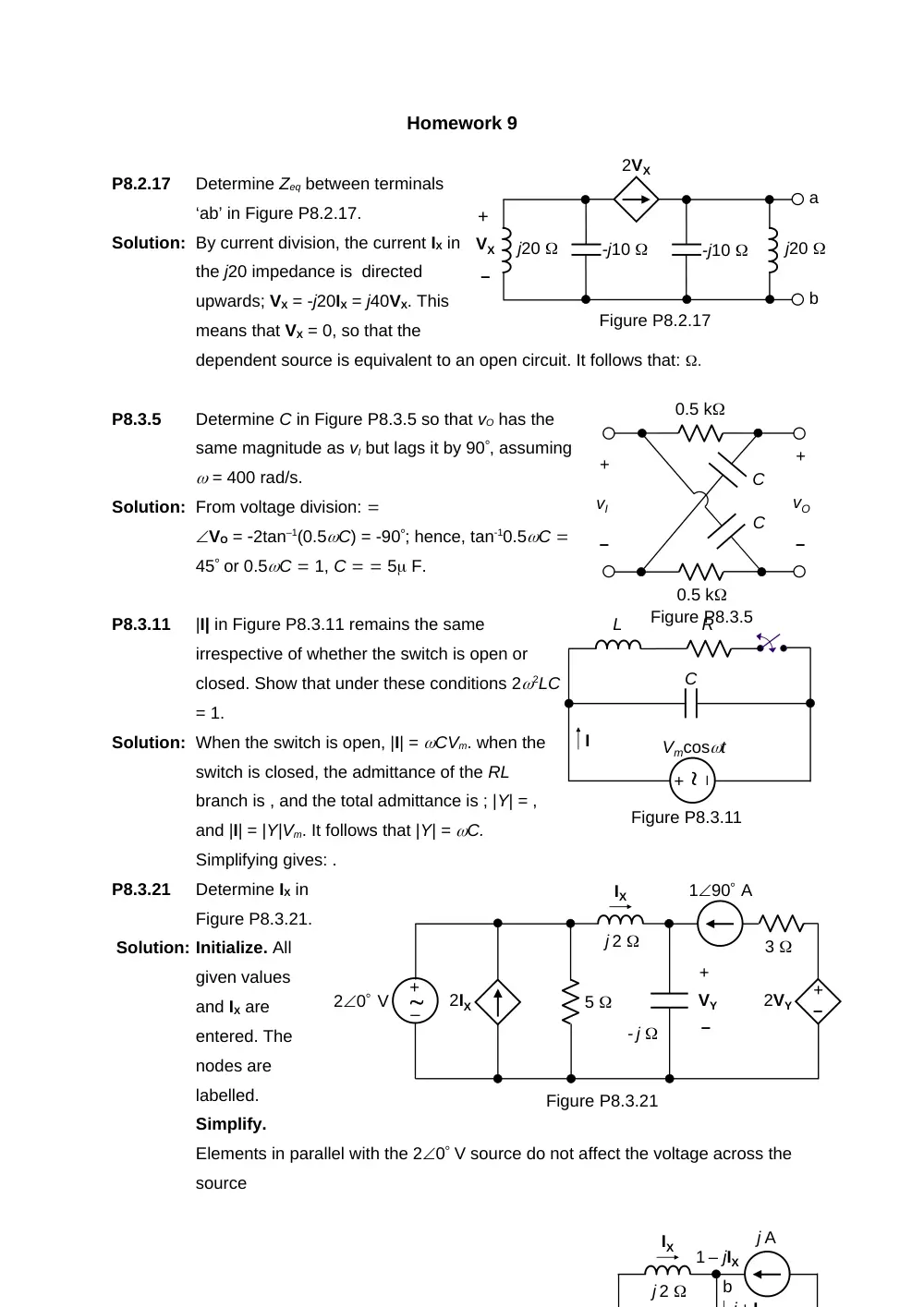
P8.2.17
Determine Zeq between terminals
‘ab’ in Figure P8.2.17.
Solution: By current division, the current IX in
the j20 impedance is directed
upwards; VX = -j20IX = j40VX. This
means that VX = 0, so that the
dependent source is equivalent to an open circuit. It follows that: .
P8.3.5
Determine C in Figure P8.3.5 so that vO has the
same magnitude as vI but lags it by 90, assuming
= 400 rad/s.
Solution: From voltage division:
VO = 2tan–1(0.5C) = -90; hence, tan-10.5C
45 or 0.5C 1, C 5 F.
P8.3.11
|I| in Figure P8.3.11 remains the same
irrespective of whether the switch is open or
closed. Show that under these conditions 22LC
= 1.
Solution: When the switch is open, |I| = CVm. when the
switch is closed, the admittance of the RL
branch is , and the total admittance is ; |Y| = ,
and |I| = |Y|Vm. It follows that |Y| = C.
Simplifying gives: .
P8.3.21
Determine IX in
Figure P8.3.21.
Solution: Initialize. All
given values
and IX are
entered. The
nodes are
labelled.
Simplify.
Elements in parallel with the 20 V source do not affect the voltage across the
source
j20
Figure P8.2.17
2VX
a
b
-j10
j20
-j10
+
VX
–
C
C
+
–
vI
+
–
vO
0.5 k
0.5 k
Figure P8.3.5
Vmcost
C
L
R
Figure P8.3.11
I
–
+
0.5 F
+
–
vX
5cos(10t) V
Figure P8.4.4
0.2 H
0.25vX
a
b
–
+
0.01 S
- j 0.05 S
0.02 S
ISRC
0.5 S
- j 0.05 S
j 0.05 S
+
VO
–
100 A
Figure P8.5.2
and are therefore redundant as far as IX is concerned. Elements in series with the
190 A source do not affect the current through the branch and are redundant
as far as IX is concerned. The circuit in the frequency domain reduces to that
shown.
Deduce. The circuit is a two-essential node circuit that can be solved using
KCL. , and the current through the capacitor is . KCL gives . This gives 2 – Vbc –
2Vbc, or Vbc = 0. It follows that = -j A
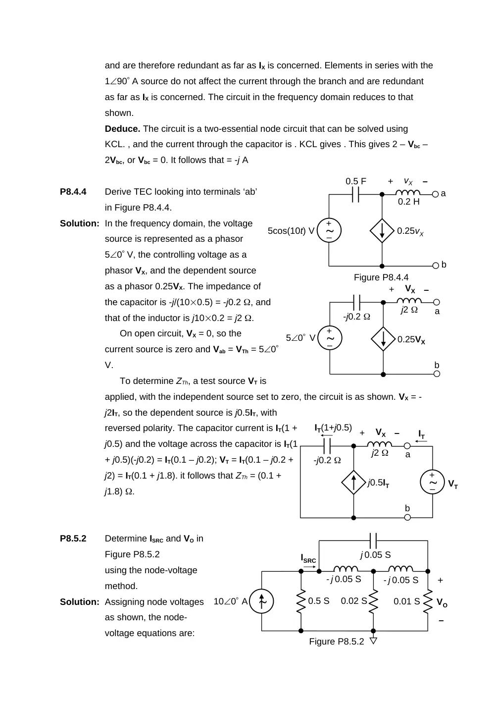
P8.4.4
Derive TEC looking into terminals ‘ab’
in Figure P8.4.4.
Solution: In the frequency domain, the voltage
source is represented as a phasor
50 V, the controlling voltage as a
phasor VX, and the dependent source
as a phasor 0.25VX. The impedance of
the capacitor is -j/(100.5) = -j0.2 , and
that of the inductor is j100.2 = j2 .
On open circuit, VX = 0, so the
current source is zero and Vab = VTh = 50
V.
To determine ZTh, a test source VT is
applied, with the independent source set to zero, the circuit is as shown. VX = -
j2IT, so the dependent source is j0.5IT, with
reversed polarity. The capacitor current is IT(1 +
j0.5) and the voltage across the capacitor is IT(1
+ j0.5)(-j0.2) = IT(0.1 – j0.2); VT = IT(0.1 – j0.2 +
j2) = IT(0.1 + j1.8). it follows that ZTh = (0.1 +
j1.8) .
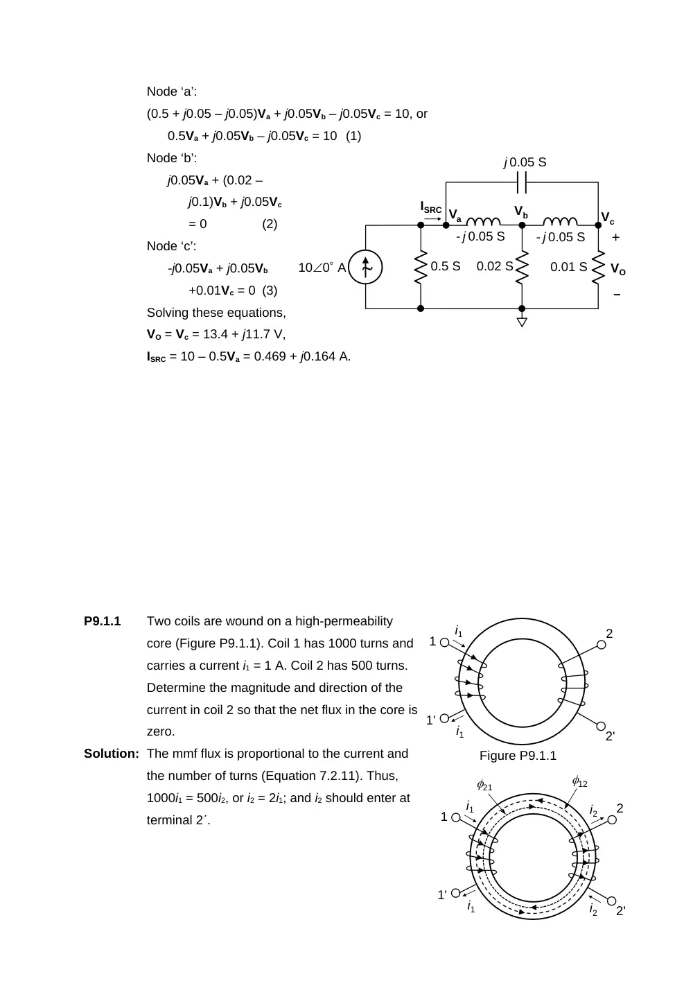
P8.5.2
Determine ISRC and VO in
Figure P8.5.2
using the node-voltage
method.
Solution: Assigning node voltages
as shown, the node-
voltage equations are:
-j0.2
+
–
VX
0.25VX
a
b
j2
50 V
–
+
-j0.2
+
–
VX
j0.5IT
a
b
j2
VT
IT
IT(1+j0.5)
–
+
Node ‘a’:
(0.5 + j0.05 – j0.05)Va + j0.05Vb – j0.05Vc = 10, or
0.5Va + j0.05Vb – j0.05Vc = 10 (1)
Node ‘b’:
j0.05Va + (0.02 –
j0.1)Vb + j0.05Vc
= 0
(2)
Node ‘c’:
-j0.05Va + j0.05Vb
+0.01Vc = 0 (3)
Solving these equations,
VO = Vc = 13.4 + j11.7 V,
ISRC = 10 – 0.5Va = 0.469 + j0.164 A.
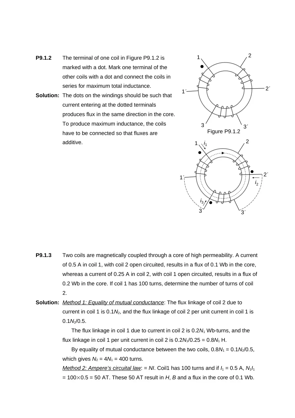
P9.1.1
Two coils are wound on a high-permeability
core (Figure P9.1.1). Coil 1 has 1000 turns and
carries a current i1 = 1 A. Coil 2 has 500 turns.
Determine the magnitude and direction of the
current in coil 2 so that the net flux in the core is
zero.
Solution: The mmf flux is proportional to the current and
the number of turns (Equation 7.2.11). Thus,
1000i1 = 500i2, or i2 = 2i1; and i2 should enter at
terminal 2.
0.01 S
- j 0.05 S
0.02 S
ISRC
0.5 S
- j 0.05 S
j 0.05 S
+
VO
–
100 A
Va
Vb
Vc
i1
i1
1'
1
2'
2
Figure P9.1.1
i1
i2
i1
1'
1
21
i2
2'
2
12
P9.1.2
The terminal of one coil in Figure P9.1.2 is
marked with a dot. Mark one terminal of the
other coils with a dot and connect the coils in
series for maximum total inductance.
Solution: The dots on the windings should be such that
current entering at the dotted terminals
produces flux in the same direction in the core.
To produce maximum inductance, the coils
have to be connected so that fluxes are
additive.
P9.1.3
Two coils are magnetically coupled through a core of high permeability. A current
of 0.5 A in coil 1, with coil 2 open circuited, results in a flux of 0.1 Wb in the core,
whereas a current of 0.25 A in coil 2, with coil 1 open circuited, results in a flux of
0.2 Wb in the core. If coil 1 has 100 turns, determine the number of turns of coil
2.
Solution: Method 1: Equality of mutual conductance: The flux linkage of coil 2 due to
current in coil 1 is 0.1N2, and the flux linkage of coil 2 per unit current in coil 1 is
0.1N2/0.5.
The flux linkage in coil 1 due to current in coil 2 is 0.2N1 Wb-turns, and the
flux linkage in coil 1 per unit current in coil 2 is 0.2N1/0.25 = 0.8N1 H.
By equality of mutual conductance between the two coils, 0.8N1 = 0.1N2/0.5,
which gives N2 = 4N1 = 400 turns.
Method 2: Ampere’s circuital law: = NI. Coil1 has 100 turns and if I1 = 0.5 A, N1I1
= 1000.5 = 50 AT. These 50 AT result in H, B and a flux in the core of 0.1 Wb.
i1
i2
i3
1
1
2
2
3
3
Figure P9.1.2
1
1
2
2
3
3
To produce a flux of 0.2 Wb due to I2, the AT should be doubled, since the
system is linear. This means that N2I2 = 100 AT. Since I2 is 0.25 A, then N2 =
100/0.25 = 400 turns. In other words, to produce twice the flux in the core with
half the current as in coil 1, coil 2 should have 4 times the number of turns, that
is, 400 turns.