
EECE 290 Exam 1 with Solution, Spring 2016
American University of Beirut · Analog Signal Processing · 8 pages · with solution



More EECE 290 files
- Exam 1 Clean Copy · Spring 2019ExamView
- Exam 1 with Solutions · Spring 2019Exam · with solutionView
- Exam 2 Clean Copy · Spring 2019ExamView
- Exam 2 with Solutions · Spring 2018Exam · with solutionView
- Exam 1 with Solutions · Spring 2018Exam · with solutionView
- Exam 1 Quiz 1 2016 · Spring 2017ExamView
- Exam 2 Quiz 2 2016 · Spring 2017ExamView
- Exam 1 · Spring 2017ExamView
Show the text of this exam
2 k
2 k
+
–
2 k
1 k
VSRC
VO
+
–
–
+
1 k
1 k
2 k
+
–
VSRC
VO
+
–
–
+
1 k
2 k
2 k
1 k
+
–
vSRC
vO
+
–
–
+
1
1 H
vSRC(t), V
t, s
0
1
3
5
2
4
A
-A
EECE 290
Quiz 1, February 20, 2016
4% (Primal Question)
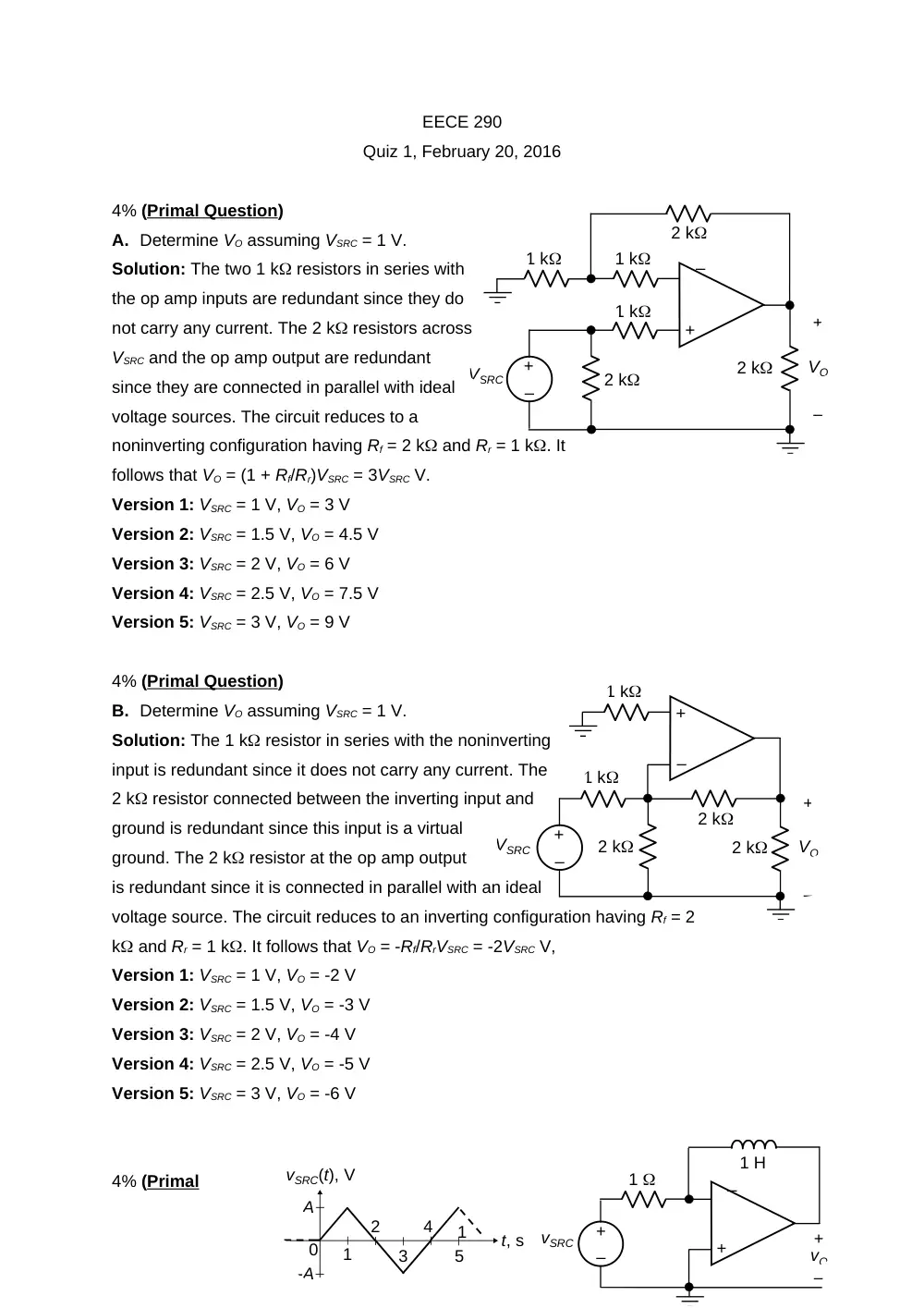
A. Determine VO assuming VSRC = 1 V.
Solution: The two 1 k resistors in series with
the op amp inputs are redundant since they do
not carry any current. The 2 k resistors across
VSRC and the op amp output are redundant
since they are connected in parallel with ideal
voltage sources. The circuit reduces to a
noninverting configuration having Rf = 2 k and Rr = 1 k. It
follows that VO = (1 + Rf/Rr)VSRC = 3VSRC V.
Version 1: VSRC = 1 V, VO = 3 V
Version 2: VSRC = 1.5 V, VO = 4.5 V
Version 3: VSRC = 2 V, VO = 6 V
Version 4: VSRC = 2.5 V, VO = 7.5 V
Version 5: VSRC = 3 V, VO = 9 V
4% (Primal Question)
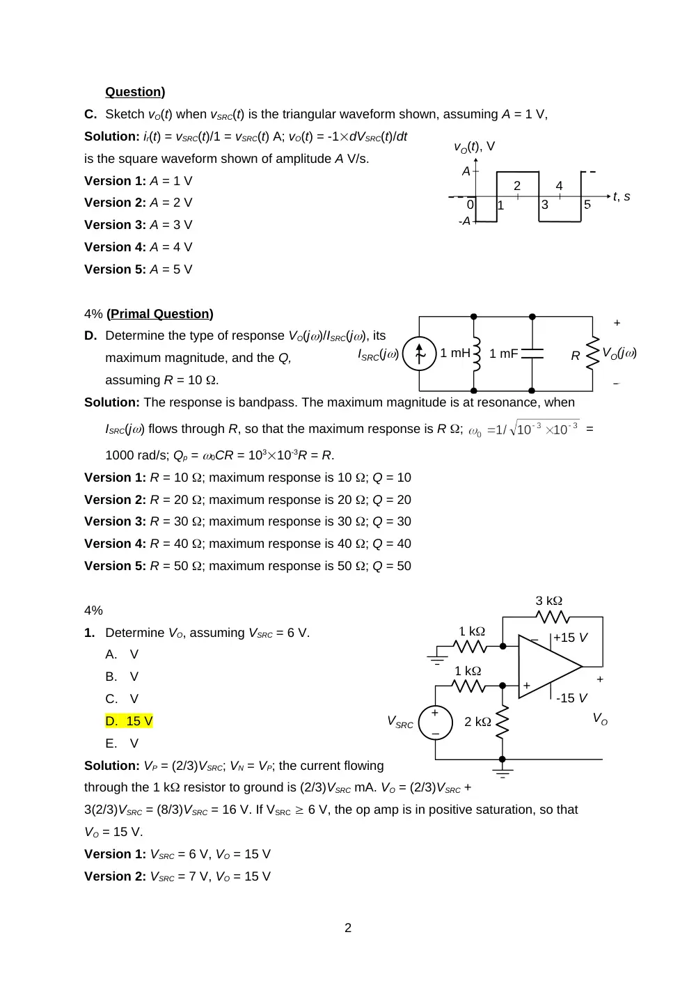
B. Determine VO assuming VSRC = 1 V.
Solution: The 1 k resistor in series with the noninverting
input is redundant since it does not carry any current. The
2 k resistor connected between the inverting input and
ground is redundant since this input is a virtual
ground. The 2 k resistor at the op amp output
is redundant since it is connected in parallel with an ideal
voltage source. The circuit reduces to an inverting configuration having Rf = 2
k and Rr = 1 k. It follows that VO = -Rf/RrVSRC = -2VSRC V,
Version 1: VSRC = 1 V, VO = -2 V
Version 2: VSRC = 1.5 V, VO = -3 V
Version 3: VSRC = 2 V, VO = -4 V
Version 4: VSRC = 2.5 V, VO = -5 V
Version 5: VSRC = 3 V, VO = -6 V
4% (Primal
1
vO(t), V
t, s
0
1
3
5
2
4
A
-A
1 mH
ISRC(j)
+
–
VO(j)
1 mF
R
2 k
+
–
VSRC
+15 V
+
–
–
+
1 k
1 k
-15 V
3 k
VO
Question)
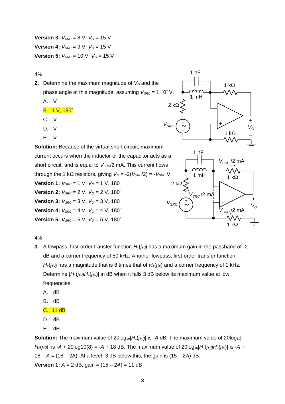
C. Sketch vO(t) when vSRC(t) is the triangular waveform shown, assuming A = 1 V,
Solution: ir(t) = vSRC(t)/1 = vSRC(t) A; vO(t) = -1dVSRC(t)/dt
is the square waveform shown of amplitude A V/s.
Version 1: A = 1 V
Version 2: A = 2 V
Version 3: A = 3 V
Version 4: A = 4 V
Version 5: A = 5 V
4% (Primal Question)
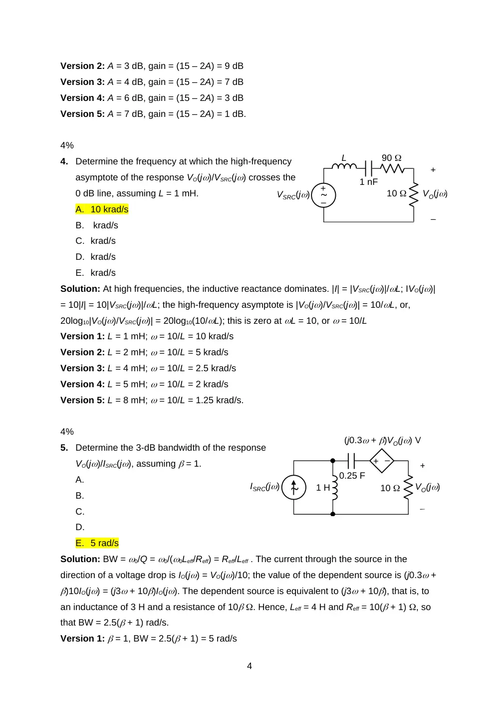
D. Determine the type of response VO(j)/ISRC(j), its
maximum magnitude, and the Q,
assuming R = 10 .
Solution: The response is bandpass. The maximum magnitude is at resonance, when
ISRC(j) flows through R, so that the maximum response is R ;
=
1000 rad/s; Qp = 0CR = 10310-3R = R.
Version 1: R = 10 ; maximum response is 10 ; Q = 10
Version 2: R = 20 ; maximum response is 20 ; Q = 20
Version 3: R = 30 ; maximum response is 30 ; Q = 30
Version 4: R = 40 ; maximum response is 40 ; Q = 40
Version 5: R = 50 ; maximum response is 50 ; Q = 50
4%
1.
Determine VO, assuming VSRC = 6 V.
A. V
B. V
C. V
D. 15 V
E. V
Solution: VP = (2/3)VSRC; VN = VP; the current flowing
through the 1 k resistor to ground is (2/3)VSRC mA. VO = (2/3)VSRC +
3(2/3)VSRC = (8/3)VSRC = 16 V. If VSRC 6 V, the op amp is in positive saturation, so that
VO = 15 V.
Version 1: VSRC = 6 V, VO = 15 V
Version 2: VSRC = 7 V, VO = 15 V
2
+
–
VSRC
VO
+
–
–
+
1 k
2 k
1 k
1 mH
1 nF
+
–
VO
+
–
–
+
1 k
2 k
1 k
1 mH
1 nF
VSRC
VSRC /2 mA
VSRC /2 mA
VSRC /2 mA
Version 3: VSRC = 8 V, VO = 15 V
Version 4: VSRC = 9 V, VO = 15 V
Version 5: VSRC = 10 V, VO = 15 V
4%
2.
Determine the maximum magnitude of VO and the
phase angle at this magnitude, assuming VSRC = 10 V.
A. V
B. 1 V, 180
C. V
D. V
E. V
Solution: Because of the virtual short circuit, maximum
current occurs when the inductor or the capacitor acts as a
short circuit, and is equal to VSRC/2 mA. This current flows
through the 1 k resistors, giving VO = -2(VSRC/2) = -VSRC V.
Version 1: VSRC = 1 V, VO = 1 V, 180
Version 2: VSRC = 2 V, VO = 2 V, 180
Version 3: VSRC = 3 V, VO = 3 V, 180
Version 4: VSRC = 4 V, VO = 4 V, 180
Version 5: VSRC = 5 V, VO = 5 V, 180
4%
3.
A lowpass, first-order transfer function H1(j) has a maximum gain in the passband of -2
dB and a corner frequency of 50 kHz. Another lowpass, first-order transfer function
H2(j) has a magnitude that is 8 times that of H1(j) and a corner frequency of 1 kHz.
Determine |H1(j)H2(j)| in dB when it falls 3 dB below its maximum value at low
frequencies.
A. dB
B. dB
C. 11 dB
D. dB
E. dB
Solution: The maximum value of 20log10|H1(j)| is -A dB. The maximum value of 20log10|
H2(j)| is -A + 20log10(8) = -A + 18 dB. The maximum value of 20log10|H1(j)H2(j)| is -A +
18 – A = (18 – 2A). At a level -3 dB below this, the gain is (15 – 2A) dB.
Version 1: A = 2 dB, gain = (15 – 2A) = 11 dB
3
–
+
VSRC(j)
L
1 nF
90
10
VO(j)
+
–
1 H
ISRC(j)
+ –
+
–
0.25 F
10
VO(j)
(j0.3 + )VO(j) V
Version 2: A = 3 dB, gain = (15 – 2A) = 9 dB
Version 3: A = 4 dB, gain = (15 – 2A) = 7 dB
Version 4: A = 6 dB, gain = (15 – 2A) = 3 dB
Version 5: A = 7 dB, gain = (15 – 2A) = 1 dB.
4%
4.
Determine the frequency at which the high-frequency
asymptote of the response VO(j)/VSRC(j) crosses the
0 dB line, assuming L = 1 mH.
A. 10 krad/s
B. krad/s
C. krad/s
D. krad/s
E. krad/s
Solution: At high frequencies, the inductive reactance dominates. |I| = |VSRC(j)|/L; IVO(j)|
= 10|I| = 10|VSRC(j)|/L; the high-frequency asymptote is |VO(j)/VSRC(j)| = 10/L, or,
20log10|VO(j)/VSRC(j)| = 20log10(10/L); this is zero at L = 10, or = 10/L
Version 1: L = 1 mH; = 10/L = 10 krad/s
Version 2: L = 2 mH; = 10/L = 5 krad/s
Version 3: L = 4 mH; = 10/L = 2.5 krad/s
Version 4: L = 5 mH; = 10/L = 2 krad/s
Version 5: L = 8 mH; = 10/L = 1.25 krad/s.
4%
5.
Determine the 3-dB bandwidth of the response
VO(j)/ISRC(j), assuming = 1.
A.
B.
C.
D.
E. 5 rad/s
Solution: BW = 0/Q = 0/(0Leff/Reff) = Reff/Leff . The current through the source in the
direction of a voltage drop is IO(j) = VO(j)/10; the value of the dependent source is (j0.3 +
)10IO(j) = (j3 + 10)IO(j). The dependent source is equivalent to (j3 + 10), that is, to
an inductance of 3 H and a resistance of 10 . Hence, Leff = 4 H and Reff = 10( + 1) , so
that BW = 2.5( + 1) rad/s.
Version 1: = 1, BW = 2.5( + 1) = 5 rad/s
4
+
–
VO
+
–
1 k
2 k
6 k
3 k
2 mA
1 mA
4 V
4 mA
3 mA
x
x
x
+
–
VO
+
–
1 k
2 k
6 k
3 k
2 mA
1 mA
Version 2: = 2, BW = 2.5( + 1) = 7.5 rad/s
Version 3: = 3, BW = 2.5( + 1) = 10 rad/s
Version 4: = 4, BW = 2.5( + 1) = 12.5 rad/s
Version 5: = 5, BW = 2.5( + 1) = 15 rad/s.
4%
6.
Given the transfer function
. Determine Q if the product of the two 3-dB
cutoff frequencies is 106 (rad/s)2.
A.
B.
C. 10
D.
E.
Solution: BW = 100 rad/s;
;
Version 1: c1c2 = 106;
= 103/100 = 10
Version 2: c1c2 = 4106;
= 2103/100 = 20
Version 3: c1c2 = 9106;
= 3103/100 = 30
Version 4: c1c2 = 16106;
= 4103/100 = 40
Version 5: c1c2 = 25106;
= 5103/100 = 50.
20%
7.
Determine VO.
Solution: VP = VN = 2(3||
6) =
22 = 4 V. A current
of 4 mA flows
in the 1 k
5
2R
Cf
Rf
–
–
+
+
2R
C
–
+
VO(j)
VSRC(j)
2R
1/sCf
Rf
–
–
+
+
2R
1/sC
–
+
VO(j)
VSRC(j)
Ir
resistor
towards ground.
The current in
The 2 k
resistor is
3 mA. It
Follows that
VO = 23 + 4 = 10 V.
20%
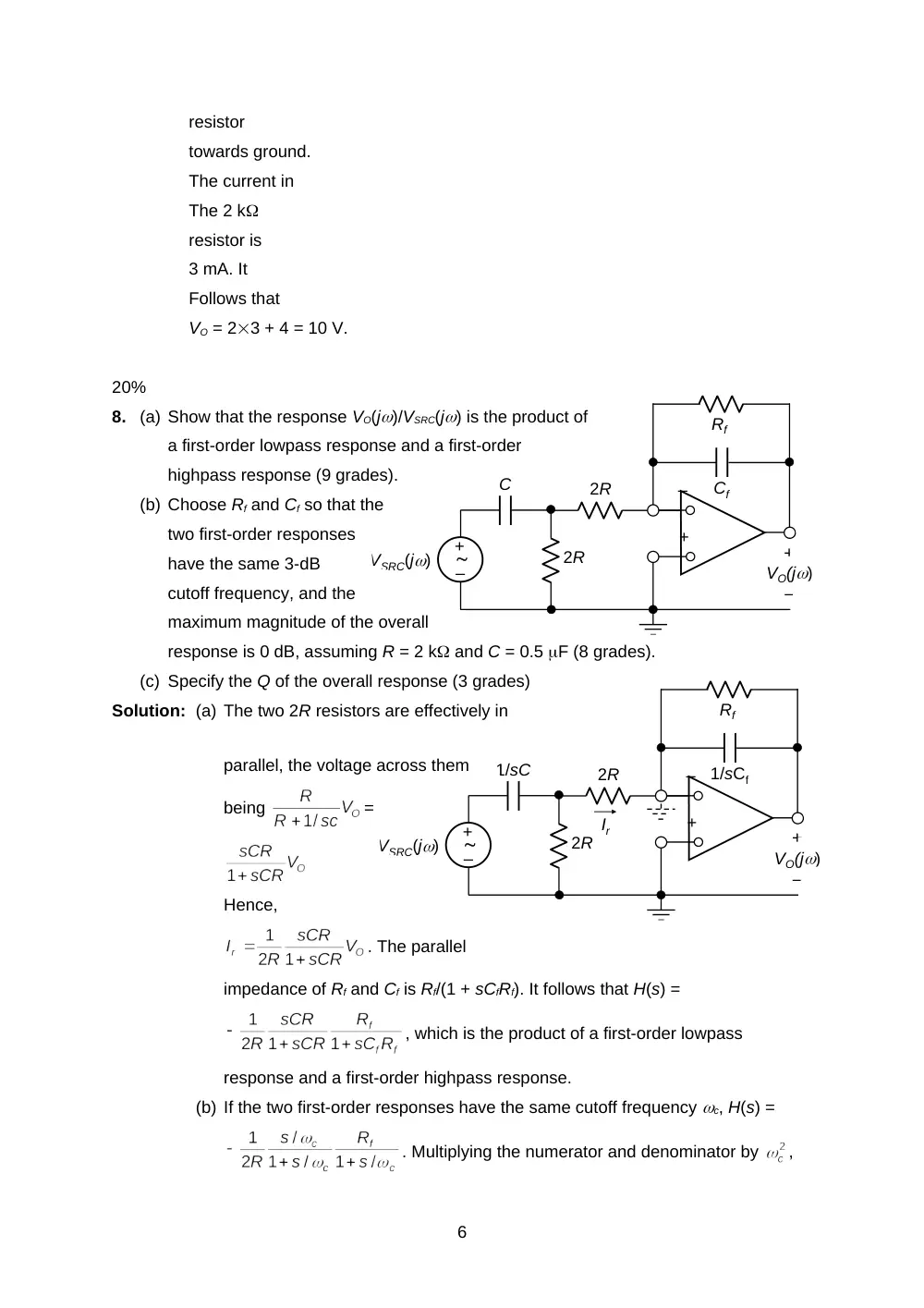
8.
(a) Show that the response VO(j)/VSRC(j) is the product of
a first-order lowpass response and a first-order
highpass response (9 grades).
(b) Choose Rf and Cf so that the
two first-order responses
have the same 3-dB
cutoff frequency, and the
maximum magnitude of the overall
response is 0 dB, assuming R = 2 k and C = 0.5 F (8 grades).
(c) Specify the Q of the overall response (3 grades)
Solution: (a) The two 2R resistors are effectively in
parallel, the voltage across them
being
=
Hence,
. The parallel
impedance of Rf and Cf is Rf/(1 + sCfRf). It follows that H(s) =
, which is the product of a first-order lowpass
response and a first-order highpass response.
(b) If the two first-order responses have the same cutoff frequency c, H(s) =
. Multiplying the numerator and denominator by
,
6
ISRC(j)
2C
2C
C
C
R
1 mH
IO(j)
ISRC(j)
2C
2C
C
C
IN
IC
IC
2IC
2IC
R
1 mH
IO(j)
100 nF
3
)
(
j
ISRC
; to have a unity magnitude
of gain, Rf = 4R = 8 k. The time constant CR = 0.510-62103 = 10-3 s.
Hence Cf = 10-3/(8103) 0.125 F.
(c) The coefficient of s in the denominator in standard form is c/Q. It follows that
Q = 0.5.
20%
9.
(a) Determine R so that Q = 10, assuming
C = 75 nF (7 grades).
(b) Derive the transfer function IO(j)/ISRC(j) (8
grades).
(c) Characterize the response in terms of the basic responses of second-order circuits (2
grades).
(d) Determine the gain in dB as 0 and at = 0 (1 grade and 2 grades).
Solution: (a) Norton’s equivalent circuit of the capacitive
bridge and current source is first determined.
The current source divides into ISRC(j)/3 through
C and 2ISRC(j)/3 through 2C. On short circuit, it is
seen that IN = ISRC(j)/3. The capacitance
looking into the capacitive bridge,
with the current source
replaced by an open circuit is
twice C in series with 2C, which is 4C/3
= 100 nF. The circuit becomes the parallel circuit shown.
=
rad/s;
k.
(b) In terms of admittances,
=
.
(c) The response is seen to be the sum of a bandpass and a lowpass response.
(d) As s 0, H(j) = 1/3, 20log10(1/3) = -9.54 dB. At = 0, s2 = -1010, and H(j0)
=
; 20log10|H(j0)| =
=
7
10.5 dB.
8