
EECE 290 Exam 2 with Solution, Spring 2011
American University of Beirut · Analog Signal Processing · 7 pages · with solution


More EECE 290 files
- Exam 1 Clean Copy · Spring 2019ExamView
- Exam 2 Clean Copy · Spring 2019ExamView
- Exam 1 with Solutions · Spring 2019Exam · with solutionView
- Exam 2 with Solutions · Spring 2018Exam · with solutionView
- Exam 1 with Solutions · Spring 2018Exam · with solutionView
- Exam 1 Quiz 1 2016 · Spring 2017ExamView
- Exam 2 Quiz 2 2016 · Spring 2017ExamView
- Exam 1 · Spring 2017ExamView
Show the text of this exam
EECE 290 Analog Signal Processing – Quiz 2
April 9, 2011
4 H
iL = 0
2 F
10 Ω
iR
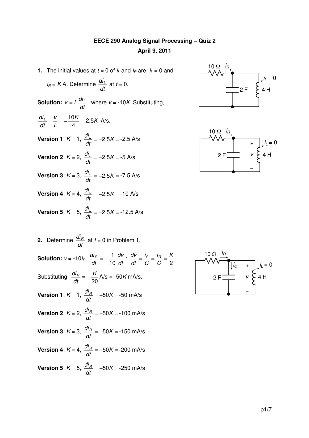
1. The initial values at t = 0 of iL and iR are: iL = 0 and
iR = K A. Determine dt
diL at t = 0.
Solution:
dt
L di
v
L
=
, where v = -10K. Substituting,
4
10K
L
v
dt
diL
= −
=
− 2.5K
A/s.
4 H
iL = 0
2 F
10 Ω
iR
–
+
v
Version 1: K = 1,
=
= −
K
dt
diL
2.5
-2.5 A/s
Version 2: K = 2,
=
= −
K
dt
diL
2.5
-5 A/s
Version 3: K = 3,
=
= −
K
dt
diL
2.5
-7.5 A/s
Version 4: K = 4,
=
= −
K
dt
diL
2.5
-10 A/s
Version 5: K = 5,
=
= −
K
dt
diL
2.5
-12.5 A/s
2. Determine dt
diR at t = 0 in Problem 1.
4 H
iL = 0
2 F
10 Ω
–
+
v
iC
iR
Solution: v = -10iR,
dt
dv
dt
diR
10
= − 1
;
2
K
C
i
C
i
dt
dv
R
C
=
=
=
.
Substituting,
20
K
dt
diR
= −
A/s = -50K mA/s.
Version 1: K = 1,
=
= −
K
dt
diR
50
-50 mA/s
Version 2: K = 2,
=
= −
K
dt
diR
50
-100 mA/s
Version 3: K = 3,
=
= −
K
dt
diR
50
-150 mA/s
Version 4: K = 4,
=
= −
K
dt
diR
50
-200 mA/s
Version 5: K = 5,
=
= −
K
dt
diR
50
-250 mA/s
p1/7
3. Which of the following statements is true of the voltage vC across C for large values of t
in Problem 1?
Version 1: vC approaches zero as an underdamped response
Version 2: vC approaches a finite value as an underdamped response
Version 3: vC approaches zero as an overdamped response
Version 4: vC approaches a finite value as an overdamped response
Version 5: vC approaches zero as a critically damped response
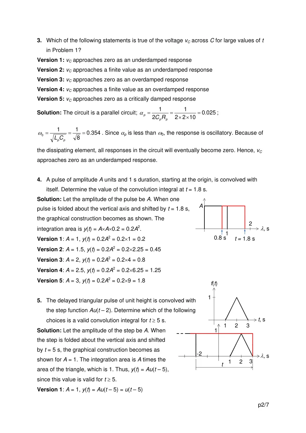
Solution: The circuit is a parallel circuit;
0 025
2 2 10
1
2
1
= .
× ×
=
=
p
p
p
C R
α
;
0 354
8
1
1
0
= .
=
=
LpCp
ω
. Since αp is less than ω0, the response is oscillatory. Because of
the dissipating element, all responses in the circuit will eventually become zero. Hence, vC
approaches zero as an underdamped response.
4. A pulse of amplitude A units and 1 s duration, starting at the origin, is convolved with
itself. Determine the value of the convolution integral at t = 1.8 s.
Solution: Let the amplitude of the pulse be A. When one
pulse is folded about the vertical axis and shifted by t = 1.8 s,
the graphical construction becomes as shown. The
integration area is y(t) = A×A×0.2 = 0.2A2.
1
λ, s
2
t = 1.8 s
0.8 s
A
Version 1: A = 1, y(t) = 0.2A2 = 0.2×1 = 0.2
Version 2: A = 1.5, y(t) = 0.2A2 = 0.2×2.25 = 0.45
Version 3: A = 2, y(t) = 0.2A2 = 0.2×4 = 0.8
Version 4: A = 2.5, y(t) = 0.2A2 = 0.2×6.25 = 1.25
Version 5: A = 3, y(t) = 0.2A2 = 0.2×9 = 1.8
5. The delayed triangular pulse of unit height is convolved with
the step function Au(t – 2). Determine which of the following
choices is a valid convolution integral for t ≥ 5 s.
1
2
1
3
f(t)
t, s
1
2
1
3
λ, s
-2
t
Solution: Let the amplitude of the step be A. When
the step is folded about the vertical axis and shifted
by t = 5 s, the graphical construction becomes as
shown for A = 1. The integration area is A times the
area of the triangle, which is 1. Thus, y(t) = Au(t – 5),
since this value is valid for t ≥ 5.
Version 1: A = 1, y(t) = Au(t – 5) = u(t – 5)
p2/7
Version 2: A = 2, y(t) = Au(t – 5) = 2u(t – 5)
Version 3: A = 3, y(t) = Au(t – 5) = 3u(t – 5)
Version 4: A = 4, y(t) = Au(t – 5) = 4u(t – 5)
Version 5: A = 5, y(t) = Au(t – 5) = 5u(t – 5)
4%
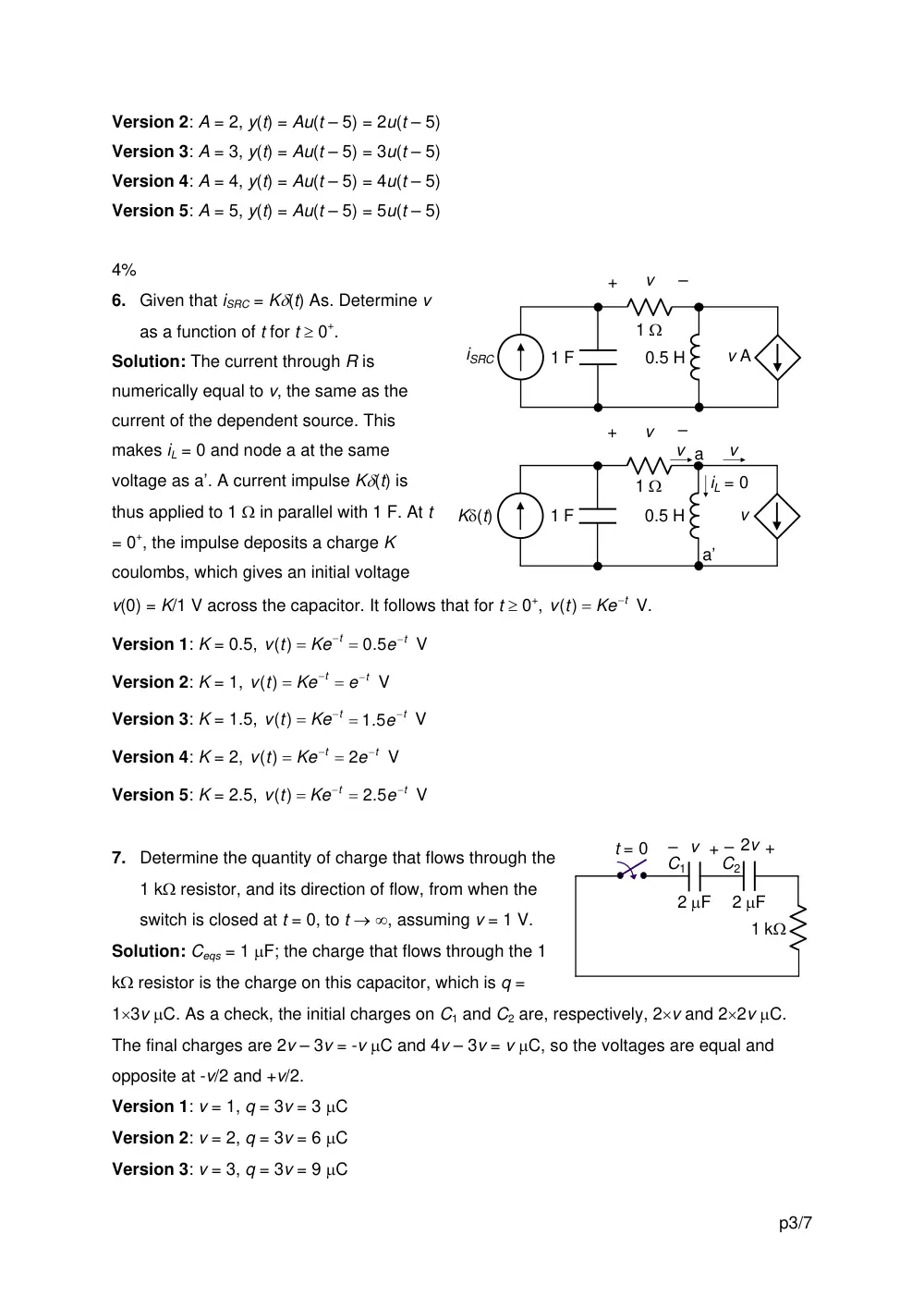
6. Given that iSRC = Kδ(t) As. Determine v
as a function of t for t ≥ 0+.
Solution: The current through R is
numerically equal to v, the same as the
current of the dependent source. This
makes iL = 0 and node a at the same
voltage as a’. A current impulse Kδ(t) is
thus applied to 1 Ω in parallel with 1 F. At t
= 0+, the impulse deposits a charge K
coulombs, which gives an initial voltage
v(0) = K/1 V across the capacitor. It follows that for t ≥ 0+,
.
Ke t
v t
−
=
)
0.5 H
1 F
1 Ω
–
+
v
v A
iSRC
0.5 H
1 F
1 Ω
–
+
v
v
Kδ(t)
iL = 0
v
v
a
a’
(
V
Version 1: K = 0.5,
V
Ke t
v t
−
( ) =
e −t
=
.5
0
Version 2: K = 1,
V
Ke t
v t
−
( ) =
e−t
=
Version 3: K = 1.5,
V
Ke t
v t
−
( ) =
e −t
=
.5
1
Version 4: K = 2,
V
Ke t
v t
−
( ) =
e−t
= 2
Version 5: K = 2.5,
V
Ke t
v t
−
( ) =
e−t
=
.5
2
7. Determine the quantity of charge that flows through the
1 kΩ resistor, and its direction of flow, from when the
switch is closed at t = 0, to t → ∞, assuming v = 1 V.
Solution: Ceqs = 1 μF; the charge that flows through the 1
kΩ resistor is the charge on this capacitor, which is q =
1×3v μC. As a check, the initial charges on C1 and C2 are, respectively, 2×v and 2×2v μC.
The final charges are 2v – 3v = -v μC and 4v – 3v = v μC, so the voltages are equal and
opposite at -v/2 and +v/2.
2 μF
2 μF
1 kΩ
–
v +
–
2v +
t = 0
C1
C2
Version 1: v = 1, q = 3v = 3 μC
Version 2: v = 2, q = 3v = 6 μC
Version 3: v = 3, q = 3v = 9 μC
p3/7
Version 4: v = 4, q = 3v = 12 μC
Version 5: v = 5, q = 3v = 15 μC
8. Determine the energy dissipated in the resistor from t = 0 to t → ∞ in Problem 7.
Solution: Method 1: The power dissipated is that stored in Ceqs, where Ceqs = 1 μF, the initial
voltage is 3v and the charge on this capacitor is 3v μC. The stored energy is w = qv/2 =
4.5v2 μJ.
Method 2: The initial current through the resistor is 3v/1 = 3v mA. As a function of time, the
current is
mA, where τ = (1 μF)×(1 kΩ) = 1 ms, so that t is in ms. The energy
dissipated is
. The dimensions of the integrand are (mA)2×kΩ×ms, which
is μJ. The value is [
μJ.
τ/
3
t
ve −
v
∫
∞
0 9
dt
e
− t
×
×
2 /
2
1
τ
2 /
4.5 2
e
v
t
−
−
τ ]
2
0
4.5
v
=
∞
Version 1: v = 1, w = 4.5v2 = 4.5 μJ
Version 2: v = 2, w = 4.5v2 = 18 μJ
Version 3: v = 3, w = 4.5v2 = 40.5 μJ
Version 4: v = 4, w = 4.5v2 = 72 μJ
Version 5: v = 5, w = 4.5v2 = 112.5 μJ
9. The response of a circuit to a unit step is
, where t is in s. Determine the
response at t = 10 s to an impulse applied at t = 5 s.
/t 10
kte−
Solution: The response to an impulse at t = 0 is the time derivative of the response to a unit
impulse and is:
. The response to an impulse at t = 5 s is
. The response at t = 10 s is
/10
/10
/10)
(
t
t
te
k
ke
−
−
−
[
( − 5 /) 10]
( 5 /) 10 1
−
− −
t
ke
t
[
] =
−
−
−
−
5 /) 10
(10
ke (10 5 /) 10 1
0.5
0.5
ke−
.
Version 1: k = 1,
0.5 = 0.303
0.5
−
ke
Version 2: k = 2,
0.5 = 0.607
0.5
−
ke
Version 3: k = 3,
0.5 = 0.910
0.5
−
ke
Version 4: k = 4,
0.5 = 1.21
0.5
−
ke
Version 5: k = 5,
0.5 = 1.52
0.5
−
ke
ISRC
3 Ω
6 Ω
1 F
iR
t = 0
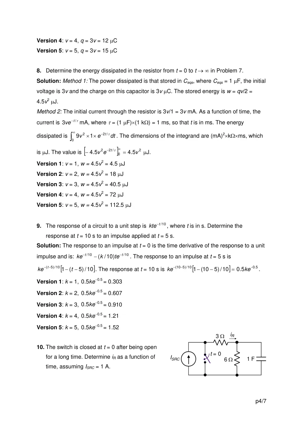
10. The switch is closed at t = 0 after being open
for a long time. Determine iR as a function of
time, assuming ISRC = 1 A.
p4/7
Solution: After the switch has been open for a long time, VC = 6ISRC. After the switch is
closed, the initial value of iR is -2ISRC. The final
value of iR is zero. The time constant, with the
switch closed, is (3||6)×1 = 2 s. Hence, iR =
/2
2
ISRCe t
−
−
ISRC
3 Ω
6 Ω
1 F
iR
t = 0
+
_
VC
Version 1: ISRC = 1 A, iR =
=
A
/2
2
ISRCe t
−
−
/2
2
e−t
−
Version 2: ISRC = 2 A, iR =
=
A
/2
2
ISRCe t
−
−
/2
4
e−t
−
Version 3: ISRC = 3 A, iR =
=
A
/2
2
ISRCe t
−
−
/2
6
e−t
−
Version 4: ISRC = 4 A, iR =
=
A
/2
2
ISRCe t
−
−
/2
8
e−t
−
Version 5: ISRC = 5 A, iR =
=
A
/2
2
ISRCe t
−
−
/2
10
e−t
−
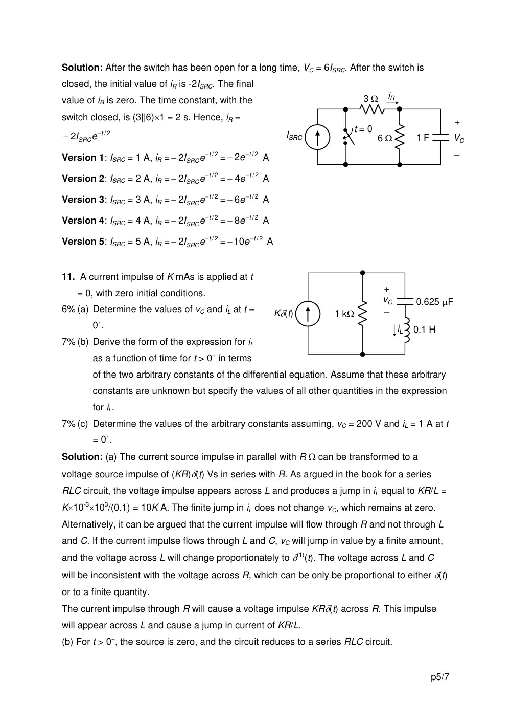
11. A current impulse of K mAs is applied at t
= 0, with zero initial conditions.
6% (a) Determine the values of vC and iL at t =
0+.
7% (b) Derive the form of the expression for iL
as a function of time for t > 0+ in terms
of the two arbitrary constants of the differential equation. Assume that these arbitrary
constants are unknown but specify the values of all other quantities in the expression
for iL.
Kδ(t)
1 kΩ
–
+
vC
0.1 H
0.625 μF
iL
7% (c) Determine the values of the arbitrary constants assuming, vC = 200 V and iL = 1 A at t
= 0+.
Solution: (a) The current source impulse in parallel with R Ω can be transformed to a
voltage source impulse of (KR)δ(t) Vs in series with R. As argued in the book for a series
RLC circuit, the voltage impulse appears across L and produces a jump in iL equal to KR/L =
K×10-3×10³/(0.1) = 10K A. The finite jump in iL does not change vC, which remains at zero.
Alternatively, it can be argued that the current impulse will flow through R and not through L
and C. If the current impulse flows through L and C, vC will jump in value by a finite amount,
and the voltage across L will change proportionately to δ(1)(t). The voltage across L and C
will be inconsistent with the voltage across R, which can be only be proportional to either δ(t)
or to a finite quantity.
The current impulse through R will cause a voltage impulse KRδ(t) across R. This impulse
will appear across L and cause a jump in current of KR/L.
(b) For t > 0+, the source is zero, and the circuit reduces to a series RLC circuit.
p5/7
4
10
.1 0.625
0
1
1
6
0
=
×
×
=
=
−
LC
ω
krad/s;
5
0.1
2
1000
2
=
×
=
=
L
R
α
krad/s. Since α > ω0, the
response is overdamped,
2
4
5
5
2
2
1
= −
−
s = − +
krad/s and
8
4
5
5
2
2
2
= −
−
−
s = −
krad/s. It follows that
A, where t is in ms.
t
t
L
Be
Ae
i
8
2
−
−
+
=
(c) At t = 0+, A + B = 1;
t
t
e
B
e
A
q
8000
2000
8000
2000
−
−
−
= −
C, where the constant of integration
is zero since q → 0 as t → ∞; at t = 0+,
−
×
−
=
1.25
103
A
C
q
vC
,
5
B ×103
or
5
10
1.25
10
200
3
3
×
−
×
= −
B
A
, or 4A + B = -1. This gives A = -2/3 A and B = 5/3 A.
Alternatively,
(
t )
t
i
L
Be
Ae
dt
d
L
v
L
8
2
8
2
0.1
−
−
−
−
=
=
H×A/ms, or
(
t )
t
L
Be
Ae
v
8
2
8
2
100
−
−
−
−
=
V,
or -vL/100 = 2A + 8B at t = 0+. But vL + vC + vR = 0, or -vL = vC + vR. This gives, 2A + 8B =
(200 + 1000)/100. Hence, A + 4B = 6, which gives the same values for A and B.
Version 1: (a) K = 0.1; iL(0+) = 10K = 1 A, vC(0+) = 0
Version 2: (a) K = 0.2; iL(0+) = 10K = 2 A, vC(0+) = 0
Version 3: (a) K = 0.3; iL(0+) = 10K = 3 A, vC(0+) = 0
Version 4: (a) K = 0.4; iL(0+) = 10K = 4 A, vC(0+) = 0
Version 5: (a) K = 0.5; iL(0+) = 10K = 5 A, vC(0+) = 0
1
2
1
2
3
3
f(t)
t, s
1
2
3
g(t)
-1
4
1
2
3
t, s
4
12. Given the two functions
f(t) and g(t) shown.
15% (a) Sketch y(t) =
f(t)∗g(t) as function
of t.
5% (b) Verify y(t) from the
product of two
polynomials.
Solution: (a) When f(t) is folded, it
becomes as shown. The convolution
integral is zero until t = 3, when side aa’
coincides with g(1). At t = 4, aa’ coincides
with g(2), and the area under the product of
the two functions is 3×2 = 6. At t = 5, aa’
coincides with g(3), and the area under the
product of the two functions is 3×2 – 1×2 = 4. At t = 6, aa’ coincides with g(4), and the area
-1
-2
-3
1
2
3
-1
-4
1
2
3
t, s
4
a
a’
b
b’
p6/7
under the product of the two functions is -
1×2 + 2×2 = 2. At t = 7, bb’ coincides with
g(3), and the area under the product of
the two functions is 2×2 = 4. At t = 8, bb’
coincides with g(4), and the area under
the product of the two functions is back to
zero. The convolution function y(t) is as
shown.
2
6
1
2
3
t, s
4
5
6
7
8
4
(4,6)
(5,4) (7,4)
(6,2)
y(t)
(b) To derive y(t) In terms of a polynomial, f(t) and g(t) are assumed to both start at t = 0. f(t)
is divided into two successive 1 s intervals, each of amplitude 2 units. Thus, as polynomials
in x, f(x) = 2x + 2, and g(x) = 3x2 – x + 2. The product f(x)g(x) = 6x3 + 4x2 + 2x + 4. The non-
zero breakpoints are thus at (1,6), (2,4), (3,2), and (4,4). For the given functions, the total
shift in time from the origin is 3 s. Because the system is linear and time-invariant, as
assumed in the derivation of the convolution integral, the 3 s is added to the time
coordinates of the breakpoints from the product of polynomials to give the non-zero
breakpoints of y(t) in the figure.
12 V
–
+
t = 0
2 H
3 H
3 Ω
6 Ω
4 Ω
iL1
iR1
13. The switch is moved at t = 0 after having
been in the first position for a long time,
with iL1 initially zero. Determine, as a
function of t, for t ≥ 0+:
10% (a) iR1
10% (b) iL1
Solution: After switching, the circuit becomes as shown, where at t = 0+: iL2 = 12/4 = 3 A, iL1
= 0, iR = 3 A, v = 3×2 = 6 V. As t → ∞, v = 0. The time constant is
(2||3)/2 = 1.2/2 = 0.6 s. Hence v =
/ 0.6 V.
6
t
e−
p7/7
(a) It follows that
/0.6
1
6
t
R
e
v
i
= − −
= −
A
(b) iL1 can be determined from conservation of flux linkage in the
loop formed by the two inductors. At t = 0+, going clockwise around the loop, the total flux
linkage is 3×2 + 0 = 6 Wb-T. As t → ∞, the currents in the two inductors are equal in
magnitude. Going clockwise around the loop, iL2×5 = 6 Wb-T, so that iL1 = -iL2 = -1.2 A. It
follows that
) A.
1.2(1
1.2)
(0
1.2
/0.6
/0.6
1
t
t
L
e
e
i
−
−
−
= −
+
+
−
=
–
2 H
3 H
2 Ω
iL1
iL2
iR
+
v
Alternatively,
[
]
(
/0.6 )
0
0.6
/
0
/0.6
1
0
1
1.2 1
2
6
3
1
(0)
1
t
t
t
t
t
L
t
L
e
e
dt
e
i
vdt
L
i
−
−
−
−
= −
= − −
= −
+
= −
∫
∫
A.