
EECE 290 Exam 2 with solution, Spring 2015
American University of Beirut · Analog Signal Processing · 8 pages · with solution

More EECE 290 files
- Exam 1 Clean Copy · Spring 2019ExamView
- Exam 2 Clean Copy · Spring 2019ExamView
- Exam 1 with Solutions · Spring 2019Exam · with solutionView
- Exam 2 with Solutions · Spring 2018Exam · with solutionView
- Exam 1 with Solutions · Spring 2018Exam · with solutionView
- Exam 1 Quiz 1 2016 · Spring 2017ExamView
- Exam 2 Quiz 2 2016 · Spring 2017ExamView
- Exam 1 · Spring 2017ExamView
Show the text of this exam
EECE 290
Quiz 2, Mach 21, 2015
4% (Primal Question)
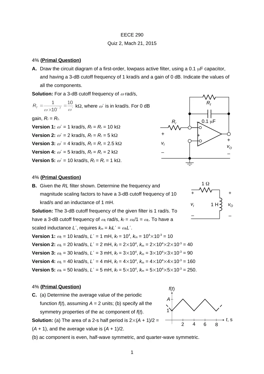
A. Draw the circuit diagram of a first-order, lowpass active filter, using a 0.1 F capacitor,
and having a 3-dB cutoff frequency of 1 krad/s and a gain of 0 dB. Indicate the values of
all the components.
Solution: For a 3-dB cutoff frequency of rad/s,
k, where is in krad/s. For 0 dB
gain, Rr = Rf.
Version 1: = 1 krad/s, Rf = Rr = 10 k
Version 2: = 2 krad/s, Rf = Rr = 5 k
Version 3: = 4 krad/s, Rf = Rr = 2.5 k
Version 4: = 5 krad/s, Rf = Rr = 2 k
Version 5: = 10 krad/s, Rf = Rr = 1 k.
4% (Primal Question)
B. Given the RL filter shown. Determine the frequency and
magnitude scaling factors to have a 3-dB cutoff frequency of 10
krad/s and an inductance of 1 mH.
Solution: The 3-dB cutoff frequency of the given filter is 1 rad/s. To
have a 3-dB cutoff frequency of c rad/s, kf = c/1 = c. To have a
scaled inductance L, requires km = kfL = cL.
Version 1: c = 10 krad/s, L = 1 mH, kf = 104, km = 10410-3 = 10
Version 2: c = 20 krad/s, L = 2 mH, kf = 2104, km = 2104210-3 = 40
Version 3: c = 30 krad/s, L = 3 mH, kf = 3104, km = 3104310-3 = 90
Version 4: c = 40 krad/s, L = 4 mH, kf = 4104, km = 4104410-3 = 160
Version 5: c = 50 krad/s, L = 5 mH, kf = 5104, km = 5104510-3 = 250.
4% (Primal Question)
C. (a) Determine the average value of the periodic
function f(t), assuming A = 2 units; (b) specify all the
symmetry properties of the ac component of f(t).
Solution: (a) The area of a 2-s half period is 2(A + 1)/2 =
(A + 1), and the average value is (A + 1)/2.
(b) ac component is even, half-wave symmetric, and quarter-wave symmetric.
1
Rr
0.1 F
Rf
vI
–
+
–
–
+
vO
+
1
A
2
6
4
f(t)
8
t, s
vO
+
–
vI
+
–
1 H
1
–
+
–
+
500
1 mH
1 k
–
+
VO(j)
VSRC(j)
2 nF
Version 1: A = 2, a0 = 1.5
Version 2: A = 3, a0 = 2
Version 3: A = 4, a0 = 2.5
Version 4: A = 5, a0 = 3
Version 5: A = 6, a0 = 3.5.
4% (Primal Question)
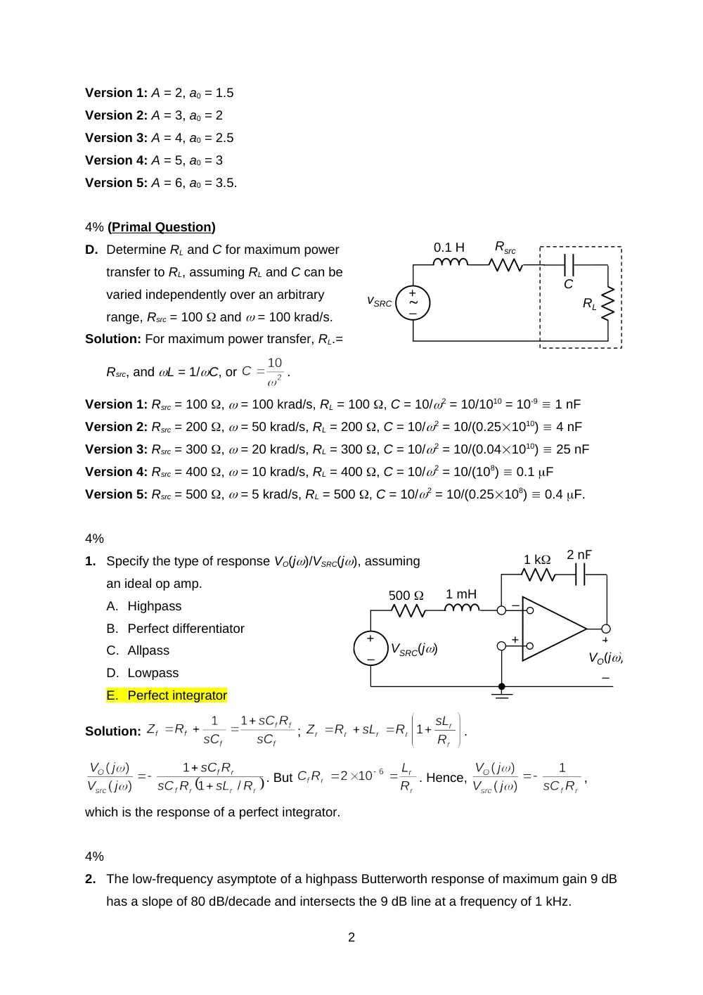
D. Determine RL and C for maximum power
transfer to RL, assuming RL and C can be
varied independently over an arbitrary
range, Rsrc = 100 and = 100 krad/s.
Solution: For maximum power transfer, RL.=
Rsrc, and L = 1/C, or
.
Version 1: Rsrc = 100 , = 100 krad/s, RL = 100 , C = 10/2 = 10/1010 = 10-9 1 nF
Version 2: Rsrc = 200 , = 50 krad/s, RL = 200 , C = 10/2 = 10/(0.251010) 4 nF
Version 3: Rsrc = 300 , = 20 krad/s, RL = 300 , C = 10/2 = 10/(0.041010) 25 nF
Version 4: Rsrc = 400 , = 10 krad/s, RL = 400 , C = 10/2 = 10/(108) 0.1 F
Version 5: Rsrc = 500 , = 5 krad/s, RL = 500 , C = 10/2 = 10/(0.25108) 0.4 F.
4%
1.
Specify the type of response VO(j)/VSRC(j), assuming
an ideal op amp.
A. Highpass
B. Perfect differentiator
C. Allpass
D. Lowpass
E. Perfect integrator
Solution:
;
.
. But
. Hence,
,
which is the response of a perfect integrator.
4%
2.
The low-frequency asymptote of a highpass Butterworth response of maximum gain 9 dB
has a slope of 80 dB/decade and intersects the 9 dB line at a frequency of 1 kHz.
2
–
+
vSRC
0.1 H
C
RL
Rsrc
10 k
vSRC
vO
+
_
+
_
–
+
10 k
1 mH
2 mH
L
Determine the frequency at which the gain is 6 dB.
A. 5 kHz
B. 1 kHz
C. 4 kHz
D. 2 kHz
E. 3 kHz
Solution: The required frequency is the 3-dB cutoff frequency, which is the same as the
corner frequency, that is, 1 kHz.
Version 1: Corner frequency = 1 kHz, fch = 1 kHz
Version 2: Corner frequency = 2 kHz, fch = 2 kHz
Version 3: Corner frequency = 3 kHz, fch = 3 kHz
Version 4: Corner frequency = 4 kHz, fch = 4 kHz
Version 5: Corner frequency = 5 kHz, fch = 5 kHz.
4%
3.
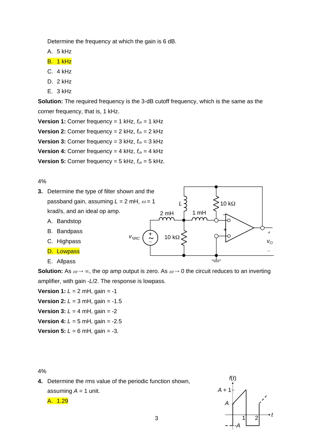
Determine the type of filter shown and the
passband gain, assuming L = 2 mH, = 1
krad/s, and an ideal op amp.
A. Bandstop
B. Bandpass
C. Highpass
D. Lowpass
E. Allpass
Solution: As , the op amp output is zero. As 0 the circuit reduces to an inverting
amplifier, with gain -L/2. The response is lowpass.
Version 1: L = 2 mH, gain = -1
Version 2: L = 3 mH, gain = -1.5
Version 3: L = 4 mH, gain = -2
Version 4: L = 5 mH, gain = -2.5
Version 5: L = 6 mH, gain = -3.
4%
4.
Determine the rms value of the periodic function shown,
assuming A = 1 unit.
A. 1.29
3
A + 1
1
2
f(t)
t
A
-A
–
+
vSRC
j15
-jX
7
5
Load
B. 3.27
C. 2.27
D. 5.26
E. 4.26
Solution: For 0 t 1, f(t) = t + A. The area under the square is
+ A21 =
=
. The mean square is
, and Frms =
.
Version 1: A = 1, Frms =
= 1.29
Version 2: A = 2, Frms =
= 2.27
Version 3: A = 3, Frms =
= 3.27
Version 4: A = 4, Frms =
= 4.26
Version 5: A = 5, Frms =
= 5.26.
4%
5.
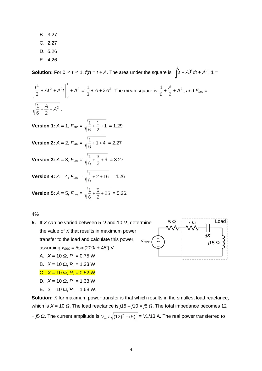
If X can be varied between 5 and 10 , determine
the value of X that results in maximum power
transfer to the load and calculate this power,
assuming vSRC = 5sin(200t + 45) V.
A. X = 10 , PL = 0.75 W
B. X = 10 , PL = 1.33 W
C. X = 10 , PL = 0.52 W
D. X = 10 , PL = 1.33 W
E. X = 10 , PL = 1.68 W.
Solution: X for maximum power transfer is that which results in the smallest load reactance,
which is X = 10 . The load reactance is j15 – j10 = j5 . The total impedance becomes 12
+ j5 . The current amplitude is
= Vm/13 A. The real power transferred to
4
–
+
10 V
rms
-j15
-j10
j10
2
1:a
RL
j15
+
–
+
_
VI(s)
+
_
VO(s)
Rf
1/sC
R
the load is PL =
.
Version 1: Vm = 5 V, PL = 25/48.286 = 0.52 W
Version 2: Vm = 6 V, PL = 36/48.286 = 0.75 W
Version 3: Vm = 7 V, PL = 49/48.286 = 1.01 W
Version 4: Vm = 8 V, PL = 64/48.286 = 1.33 W
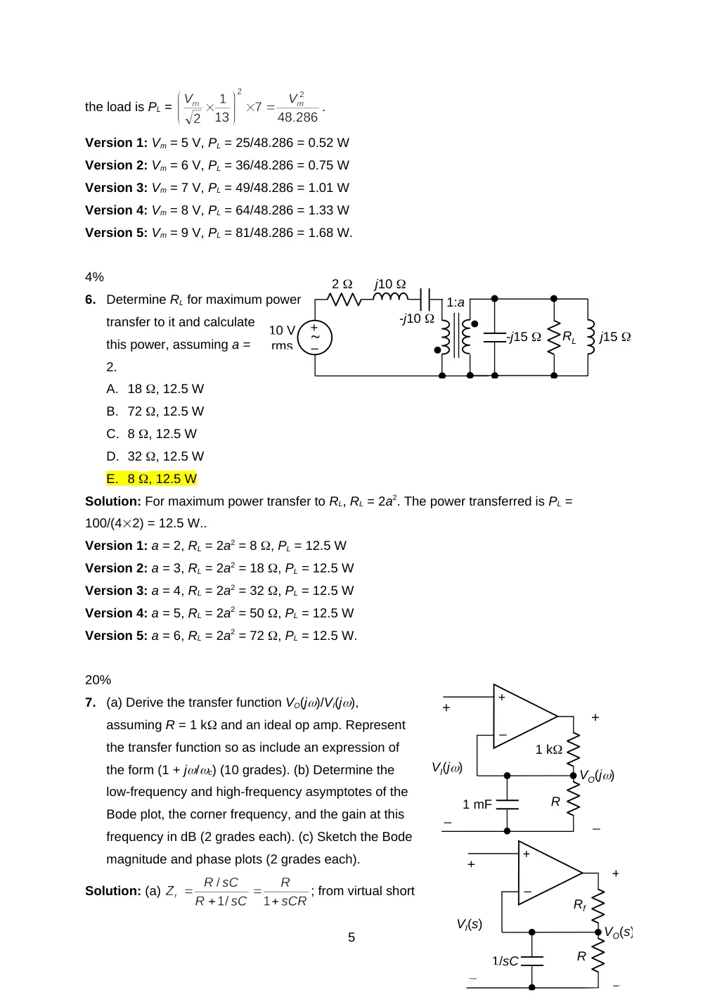
Version 5: Vm = 9 V, PL = 81/48.286 = 1.68 W.
4%
6.
Determine RL for maximum power
transfer to it and calculate
this power, assuming a =
2.
A. 18 , 12.5 W
B. 72 , 12.5 W
C. 8 , 12.5 W
D. 32 , 12.5 W
E. 8 , 12.5 W
Solution: For maximum power transfer to RL, RL = 2a2. The power transferred is PL =
100/(42) = 12.5 W..
Version 1: a = 2, RL = 2a2 = 8 , PL = 12.5 W
Version 2: a = 3, RL = 2a2 = 18 , PL = 12.5 W
Version 3: a = 4, RL = 2a2 = 32 , PL = 12.5 W
Version 4: a = 5, RL = 2a2 = 50 , PL = 12.5 W
Version 5: a = 6, RL = 2a2 = 72 , PL = 12.5 W.
20%
7.
(a) Derive the transfer function VO(j)/VI(j),
assuming R = 1 k and an ideal op amp. Represent
the transfer function so as include an expression of
the form (1 + j/c) (10 grades). (b) Determine the
low-frequency and high-frequency asymptotes of the
Bode plot, the corner frequency, and the gain at this
frequency in dB (2 grades each). (c) Sketch the Bode
magnitude and phase plots (2 grades each).
Solution: (a)
; from virtual short
5
+
–
+
_
VI(j)
+
_
VO(j)
R
1 k
1 mF
Frequency, Hz
0.01
0.03
0.1
0.3
1.0
3.0
10
0
10
20
30
40
dB
0d
50d
100d
Frequency, Hz
0.01
0.03
0.1
0.3
1.0
3.0
10
2A
1
3
2
f(t)
4
t, s
A
-A
-2A
circuit,
; hence, H(j) =
K + j10-3103 = K(1 + j/K), where K = (1 + 1/R), R is in k.
(b)
; when = 0, |H(j)| = K; the low-frequency asymptote is 20log10|
H(j)| = 20log10K. As ,
|H(j)| = ; the high-frequency asymptote is 20log10|H(j)| = 20log10, slope = +20
dB/decade. The corner frequency is when 20log10 = 20log10K, or c = K rad/s. At this
frequency, 20log10|H(j)| = 20log10
= 20log10K + 3 dB.
(c) The Bode magnitude and phase plots are as
shown.
Version 1: R = 1 k, K = (1 + 1/R) = 2, LF
asymptote: 20log102 = 6 dB; c = 2 rad/s;
gain = 6 + 3 = 9 dB
Version 2: R = 1/2 k, K = (1 + 2) = 3, LF
asymptote: 20log103 = 9.5 dB; c = 3 rad/s;
gain = 9.5 + 3 = 12.5 dB
Version 3: R = 1/3 k, K = (1 + 3) = 4, LF asymptote:
20log104 = 12 dB; c = 4 rad/s; gain = 12 +
3 = 15 dB
Version 4: R = 1/4 k, K = (1 + 4) = 5, LF
asymptote: 20log105 = 14 dB; c = 5 rad/s;
gain = 14 + 3 = 17 dB
Version 5: R = 1/5 k, K = (1 + 5) = 6, LF
asymptote: 20log106 = 15.6 dB; c = 6 rad/s;
gain = 15.6 + 3 = 18.6 dB.
20%
8.
The first period of the periodic function f(t) is shown,
where A = 1 unit. Determine: (a) C0, C1, C2, and C3 (4
grades each); (b) Derive the amplitude and phase angle
of the third harmonic component of f(t) (2 grades each).
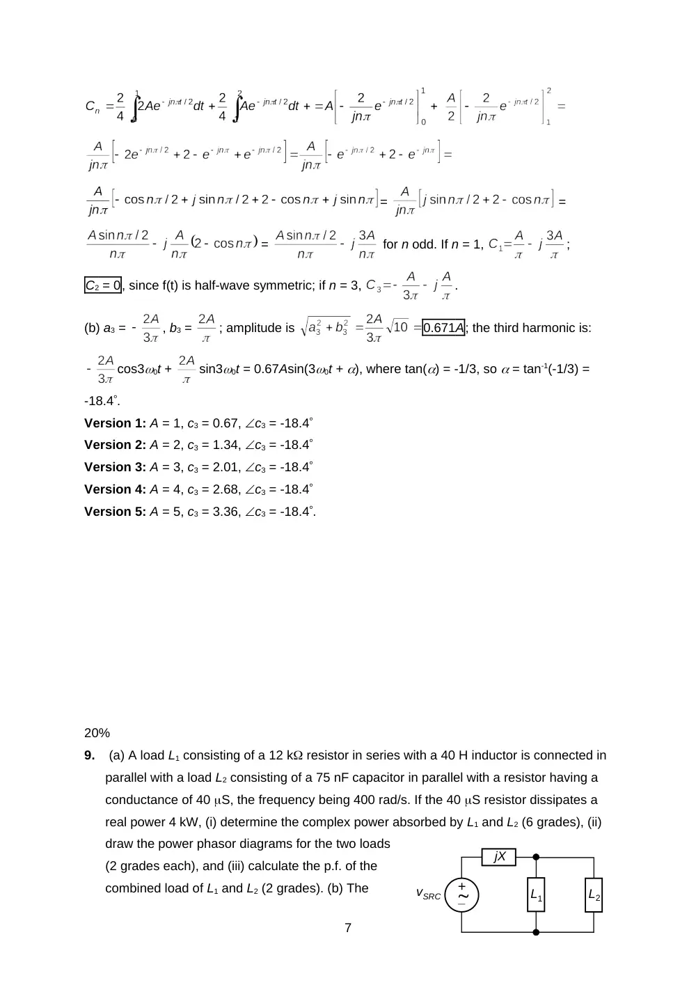
Solution: (a) f(t) is half-wave symmetric, 0 = 2/T = /2
rad/s. C0 = 0;
6
=
=
=
for n odd. If n = 1,
;
C2 = 0, since f(t) is half-wave symmetric; if n = 3,
.
(b) a3 =
, b3 =
; amplitude is
0.671A; the third harmonic is:
cos30t +
sin30t = 0.67Asin(30t + ), where tan() = -1/3, so = tan-1(-1/3) =
-18.4.
Version 1: A = 1, c3 = 0.67, c3 = -18.4
Version 2: A = 2, c3 = 1.34, c3 = -18.4
Version 3: A = 3, c3 = 2.01, c3 = -18.4
Version 4: A = 4, c3 = 2.68, c3 = -18.4
Version 5: A = 5, c3 = 3.36, c3 = -18.4.
20%
9.
(a) A load L1 consisting of a 12 k resistor in series with a 40 H inductor is connected in
parallel with a load L2 consisting of a 75 nF capacitor in parallel with a resistor having a
conductance of 40 S, the frequency being 400 rad/s. If the 40 S resistor dissipates a
real power 4 kW, (i) determine the complex power absorbed by L1 and L2 (6 grades), (ii)
draw the power phasor diagrams for the two loads
(2 grades each), and (iii) calculate the p.f. of the
combined load of L1 and L2 (2 grades). (b) The
7
+
_
L1
L2
jX
vSRC
P1
Q1
P2
Q2
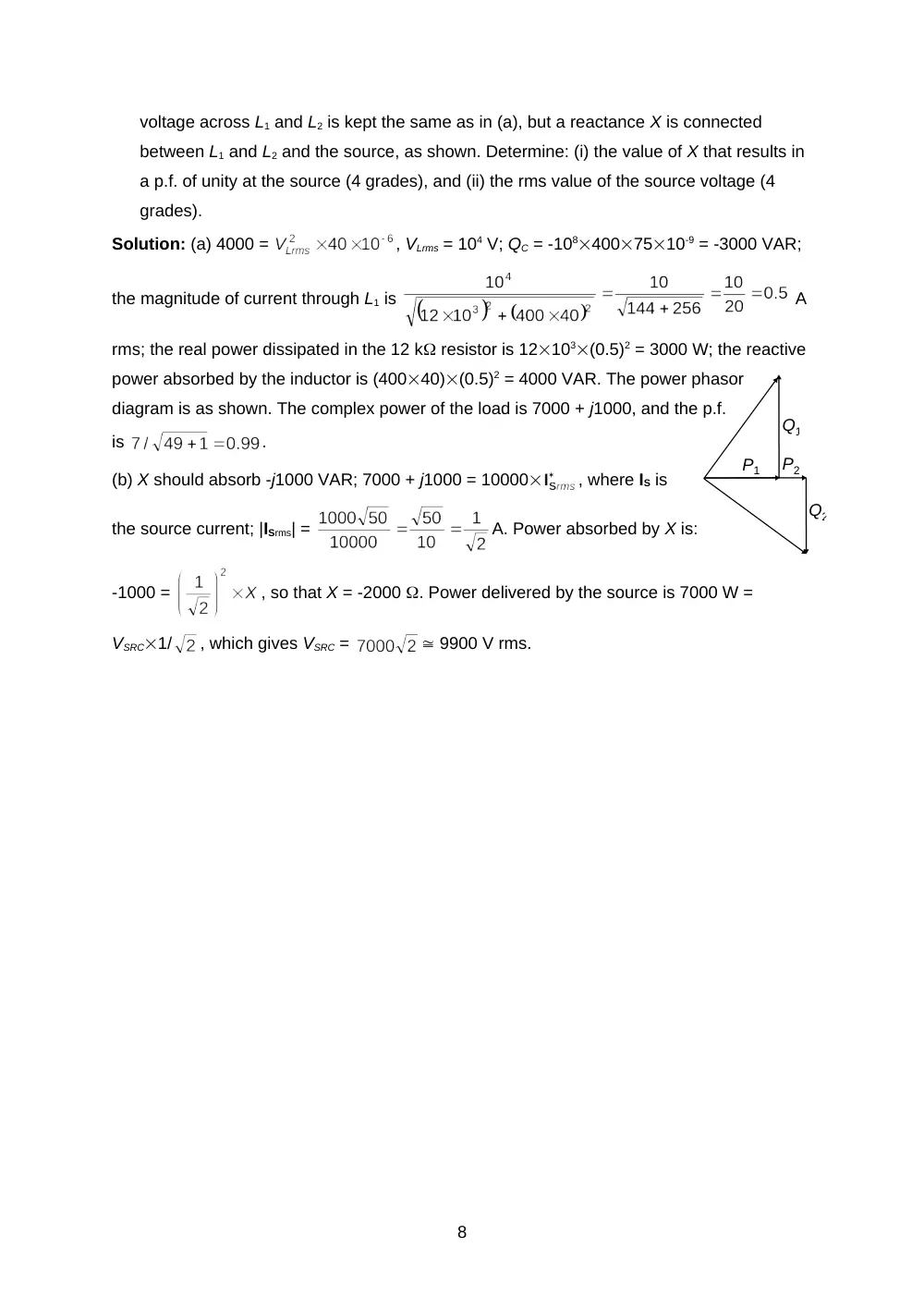
voltage across L1 and L2 is kept the same as in (a), but a reactance X is connected
between L1 and L2 and the source, as shown. Determine: (i) the value of X that results in
a p.f. of unity at the source (4 grades), and (ii) the rms value of the source voltage (4
grades).
Solution: (a) 4000 =
, VLrms = 104 V; QC = -1084007510-9 = -3000 VAR;
the magnitude of current through L1 is
A
rms; the real power dissipated in the 12 k resistor is 12103(0.5)2 = 3000 W; the reactive
power absorbed by the inductor is (40040)(0.5)2 = 4000 VAR. The power phasor
diagram is as shown. The complex power of the load is 7000 + j1000, and the p.f.
is
.
(b) X should absorb -j1000 VAR; 7000 + j1000 = 10000
, where IS is
the source current; |ISrms| =
A. Power absorbed by X is:
-1000 =
, so that X = -2000 . Power delivered by the source is 7000 W =
VSRC1/
, which gives VSRC =
9900 V rms.
8