
EECE 290 Exam 2 with Solution, Spring 2016
American University of Beirut · Analog Signal Processing · 8 pages · with solution


More EECE 290 files
- Exam 1 Clean Copy · Spring 2019ExamView
- Exam 2 Clean Copy · Spring 2019ExamView
- Exam 1 with Solutions · Spring 2019Exam · with solutionView
- Exam 2 with Solutions · Spring 2018Exam · with solutionView
- Exam 1 with Solutions · Spring 2018Exam · with solutionView
- Exam 1 Quiz 1 2016 · Spring 2017ExamView
- Exam 2 Quiz 2 2016 · Spring 2017ExamView
- Exam 1 · Spring 2017ExamView
Show the text of this exam
–
+
VSRC(j)
-j10
j20
4
t
f(t)
2
4
-2
-4
8
EECE 290
Quiz 2, Mar 19, 2016
4% (Primal Question)
A. Given the transfer function
for a normalized second-order Butterworth filter.
Determine the transfer function of the filter when the frequency is scaled to 10 rad/s.
Solution: Coefficient of s is 0/Q, where Q of the Butterworth filter is
. The constant
term is term is
.
Version 1: 0 = 10 rad/s, H(s) =
Version 2: 0 = 20 rad/s, H(s) =
Version 3: 0 = 30 rad/s, H(s) =
Version 4: 0 = 40 rad/s, H(s) =
Version 5: 0 = 50 rad/s, H(s) =
.
4% (Primal Question)
B. Enter between the parenthesis (T) or (F) according to
whether the statement is true or false, respectively:
( T )The average value of f(t) is 4
( F )The ac component of the FSE of f(t) consists of
even harmonic only
( T )The trigonometric terms of the FSE are cosine functions only
( F )The harmonics of the FSE of f(t) attenuate at a rate of approximately 1/n
(Note: 1 grade for each correct answer. No penalty for wrong answers)
4% (Primal Question)
C. Determine the reactive power absorbed by the inductor
and the capacitor, assuming VSRC(j) = 10-45 V
rms.
Solution: QL = -|VSRC(j)|2BL = -|VSRC(j)|2×[-(1/20)]; QC =
-|VSRC(j)|2BC = -|VSRC(j)|2×[(1/10)].
1
Version 1: |VSRC(j)| = 10; QL = 100/20 = 5 VAR, QC = -100/10 = -10 VAR
Version 2: |VSRC(j)| = 20; QL = 400/20 = 20 VAR, QC = -400/10 = -40 VAR
Version 3: |VSRC(j)| = 30; QL = 900/20 = 45 VAR, QC = -900/10 = -90 VAR
Version 4: |VSRC(j)| = 40; QL = 1600/20 = 80 VAR, QC = -1600/10 = -160 VAR
Version 5: |VSRC(j)| = 50; QL = 2500/20 = 125 VAR, QC = -2500/10 = -250 VAR
4% (Primal Question)
D. A source has an open circuit voltage of 10-140 V rms, a source inductance of 10 mH
and a source resistance of 10 , the frequency being 400 Hz. Determine the load that
will absorb maximum power from this source and the value of this power.
Solution: The source reactance is 2×400×10-2 = 8 . For maximum power transfer, the
load resistance should be 10 and the reactance should be -8 , which gives a
capacitance of -1/(8×800) 15.8 F. The power delivered is PL = |VSRC|2/(4*10) =
Version 1: |VSRC| = 10; PL = 100/40 = 2.5 W
Version 2: |VSRC| = 8; PL = 64/40 = 1.6 W
Version 3: |VSRC| = 6; PL = 36/40 = 0.9 W
Version 4: |VSRC| = 5; PL = 25/40 = 0.625 W
Version 5: |VSRC| = 4; PL = 16/40 = 0.4 W.
4%
1.
A highpass 4th order Butterworth filter has a passband gain of 10 and a 3-dB cutoff
frequency of 10 kHz. Determine the frequency at which the gain is 10-6.
A. Hz
B. Hz
C. Hz
D. Hz
E. 177.8 Hz
Solution: For a 4th order highpass Butterworth filter of a passband gain of 10,
. The frequency fx at which the gain is A×10-6 is small compared to fch
if A is relatively small. Hence, (fch/fx) >> 1, so that
, or =
, or,
= 177.8 Hz if A = 1. Alternatively,
fx will lie on the LF asymptote, whose slope is 80 dB/dec. The gain of 10-6 is 10-7 below the
passband gain, which corresponds to -140 dB. This is 140/80 = 7/4 decades less than 10
2
t, s
1
2
-1
-2
A
vO
+
–
–
+
–
+
–
+
1
1 F
1
1 H
vSRC
vSRC
kHz, which gives fX = 104×10-7/4 = 177.8 Hz
Version 1: A = 1,
= 177.8 Hz
Version 2: A = 2,
= 211.5 Hz
Version 3: A = 3,
= 234.0 Hz
Version 4: A = 4,
= 251.5 Hz
Version 5: A = 5,
= 265.9 Hz
4%
2.
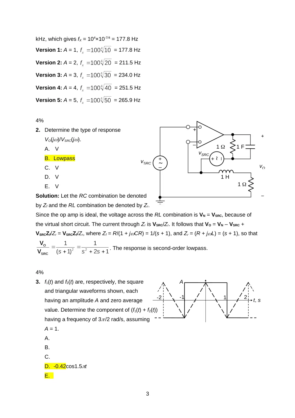
Determine the type of response
VO(j)/VSRC(j).
A. V
B. Lowpass
C. V
D. V
E. V
Solution: Let the RC combination be denoted
by Zf and the RL combination be denoted by Zr.
Since the op amp is ideal, the voltage across the RL combination is VN = VSRC, because of
the virtual short circuit. The current through Zr is VSRC/Zr. It follows that VO = VN – VSRC +
VSRCZf/Zr = VSRCZf/Zr, where Zf = R/(1 + jCR) = 1/(s + 1), and Zr = (R + jL) = (s + 1), so that
. The response is second-order lowpass.
4%
3.
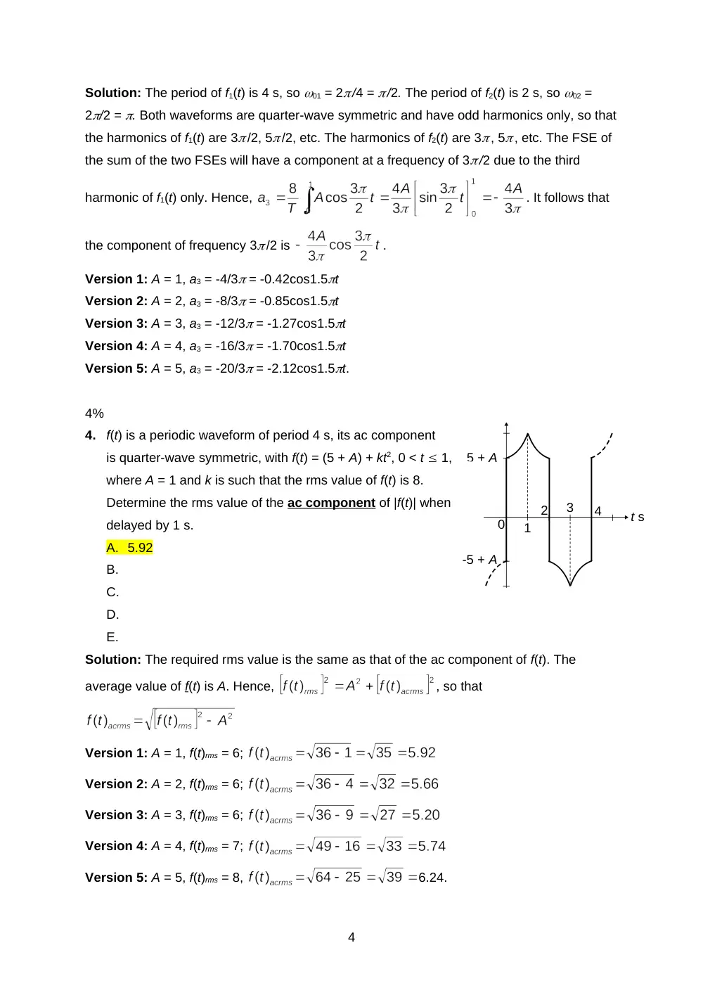
f1(t) and f2(t) are, respectively, the square
and triangular waveforms shown, each
having an amplitude A and zero average
value. Determine the component of (f1(t) + f2(t))
having a frequency of 3 /2 rad/s, assuming
A = 1.
A.
B.
C.
D. -0.42cos1.5t
E.
3
t s
0
1
3
2
4
5 + A
-5 + A
Solution: The period of f1(t) is 4 s, so 01 = 2 /4 = /2. The period of f2(t) is 2 s, so 02 =
2/2 = . Both waveforms are quarter-wave symmetric and have odd harmonics only, so that
the harmonics of f1(t) are 3 /2, 5 /2, etc. The harmonics of f2(t) are 3 , 5 , etc. The FSE of
the sum of the two FSEs will have a component at a frequency of 3 /2 due to the third
harmonic of f1(t) only. Hence,
. It follows that
the component of frequency 3 /2 is
.
Version 1: A = 1, a3 = -4/3 = -0.42cos1.5t
Version 2: A = 2, a3 = -8/3 = -0.85cos1.5t
Version 3: A = 3, a3 = -12/3 = -1.27cos1.5t
Version 4: A = 4, a3 = -16/3 = -1.70cos1.5t
Version 5: A = 5, a3 = -20/3 = -2.12cos1.5t.
4%
4.
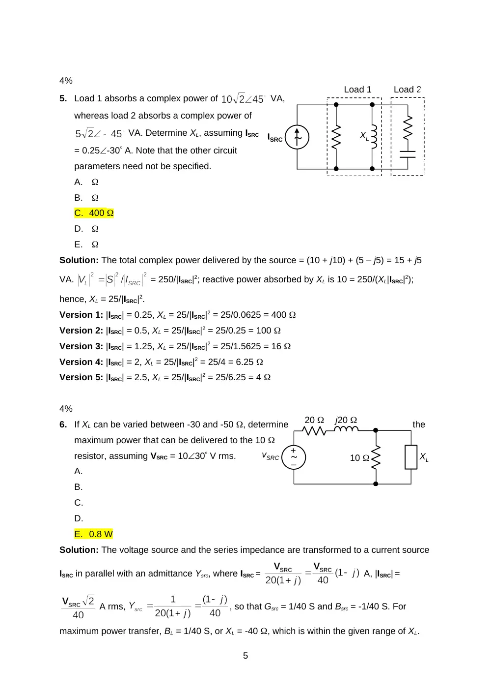
f(t) is a periodic waveform of period 4 s, its ac component
is quarter-wave symmetric, with f(t) = (5 + A) + kt2, 0 < t 1,
where A = 1 and k is such that the rms value of f(t) is 8.
Determine the rms value of the ac component of |f(t)| when
delayed by 1 s.
A. 5.92
B.
C.
D.
E.
Solution: The required rms value is the same as that of the ac component of f(t). The
average value of f(t) is A. Hence,
, so that
Version 1: A = 1, f(t)rms = 6;
Version 2: A = 2, f(t)rms = 6;
Version 3: A = 3, f(t)rms = 6;
Version 4: A = 4, f(t)rms = 7;
Version 5: A = 5, f(t)rms = 8,
6.24.
4
–
+
vSRC
j20
20
XL
10
ISRC
XL
Load 1
Load 2
4%
5.
Load 1 absorbs a complex power of
VA,
whereas load 2 absorbs a complex power of
VA. Determine XL, assuming ISRC
= 0.25-30 A. Note that the other circuit
parameters need not be specified.
A.
B.
C. 400
D.
E.
Solution: The total complex power delivered by the source = (10 + j10) + (5 – j5) = 15 + j5
VA.
= 250/|ISRC|2; reactive power absorbed by XL is 10 = 250/(XL|ISRC|2);
hence, XL = 25/|ISRC|2.
Version 1: |ISRC| = 0.25, XL = 25/|ISRC|2 = 25/0.0625 = 400
Version 2: |ISRC| = 0.5, XL = 25/|ISRC|2 = 25/0.25 = 100
Version 3: |ISRC| = 1.25, XL = 25/|ISRC|2 = 25/1.5625 = 16
Version 4: |ISRC| = 2, XL = 25/|ISRC|2 = 25/4 = 6.25
Version 5: |ISRC| = 2.5, XL = 25/|ISRC|2 = 25/6.25 = 4
4%
6.
If XL can be varied between -30 and -50 , determine
the
maximum power that can be delivered to the 10
resistor, assuming VSRC = 1030 V rms.
A.
B.
C.
D.
E. 0.8 W
Solution: The voltage source and the series impedance are transformed to a current source
ISRC in parallel with an admittance Ysrc, where ISRC =
A, |ISRC| =
A rms,
, so that Gsrc = 1/40 S and Bsrc = -1/40 S. For
maximum power transfer, BL = 1/40 S, or XL = -40 , which is within the given range of XL.
5
50 k
vO
vI
+
–
+
–
+
–
+
–
+
–
50 k
0.2 nF
50 k
50 k
10 k
10 k
100 k
0.16 F
4
5
-4
-3
t
f(t)
-
The circuit reduces to ISRC in parallel with 40 and 10 . The current in the 10 resistor is
ISRC×40/50 = 0.8ISRC. The power absorbed by the 10 resistor is PL = 0.64|ISRC|2×10 =
Version 1: |VSRC| = 10; PL = |VSRC|2/125 = 100/125 = 0.8 W
Version 2: |VSRC| = 15; PL = |VSRC|2/125 = 225/125 = 1.8 W
Version 3: |VSRC| = 20; PL = |VSRC|2/125 = 400/125 = 3.2 W
Version 4: |VSRC| = 25; PL = |VSRC|2/125 = 625/125 = 5 W
Version 5: |VSRC| = 30; PL = |VSRC|2/125 = 900/125 = 7.2 W.
20%
7.
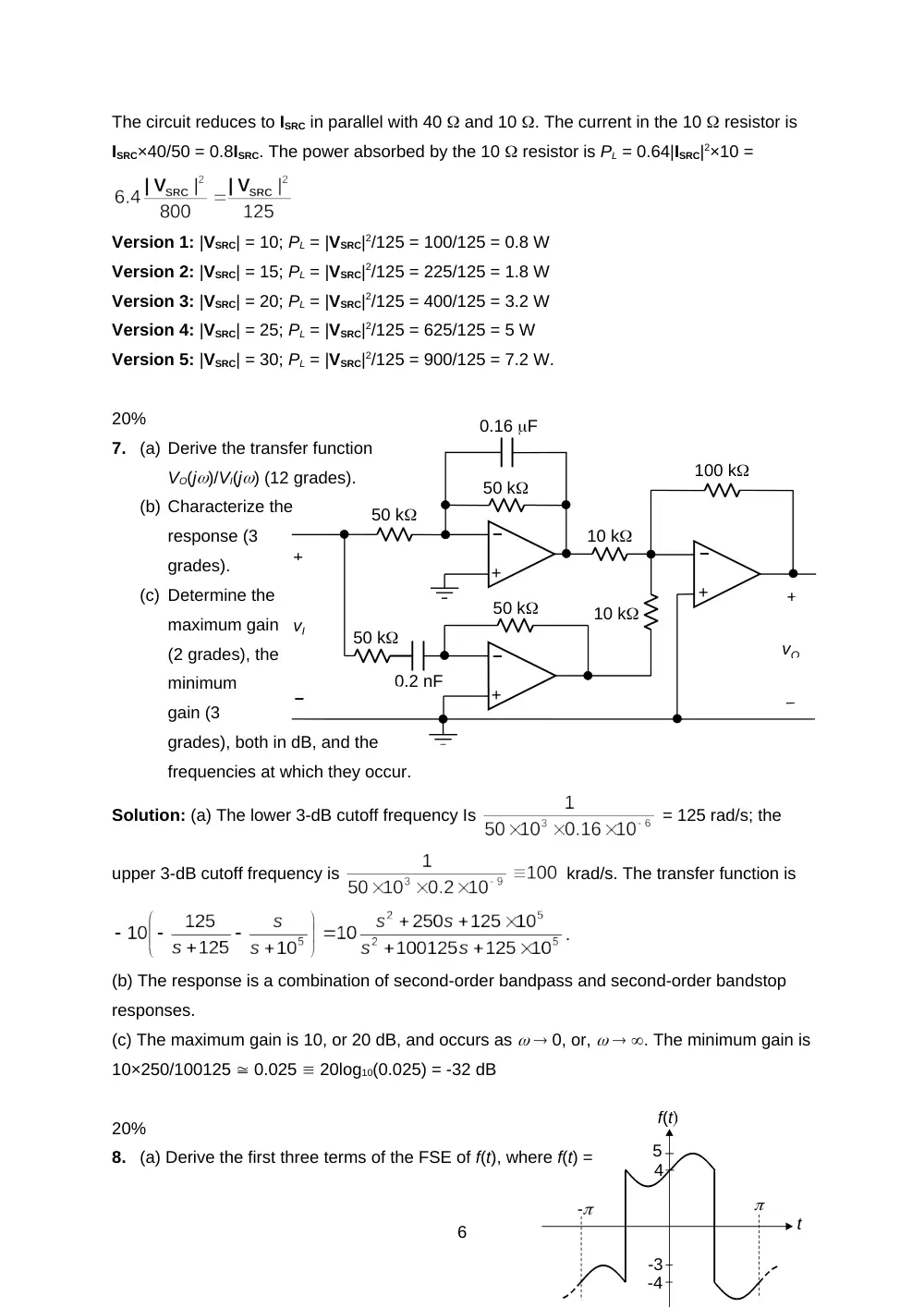
(a) Derive the transfer function
VO(j)/VI(j) (12 grades).
(b) Characterize the
response (3
grades).
(c) Determine the
maximum gain
(2 grades), the
minimum
gain (3
grades), both in dB, and the
frequencies at which they occur.
Solution: (a) The lower 3-dB cutoff frequency Is
= 125 rad/s; the
upper 3-dB cutoff frequency is
krad/s. The transfer function is
.
(b) The response is a combination of second-order bandpass and second-order bandstop
responses.
(c) The maximum gain is 10, or 20 dB, and occurs as 0, or, . The minimum gain is
10×250/100125 0.025 20log10(0.025) = -32 dB
20%
8.
(a) Derive the first three terms of the FSE of f(t), where f(t) =
6
-j40
20
50
A rms
j18
4
a
b
-j5
20
80 – j40
V rms
j10
10
a
b
–
+
4 + sin 2t, -/2 < t < /2 and f(t) = -4 + sin 2t, - t < -/2 and
/2 < t (16 grades); (b) determine these terms when f(t) is advanced by a quarter
period (4 grades).
Solution: (a) f(t) is neither odd nor even, is not half-wave
symmetric, and is of zero average. It is the sum of sin2t and an even square wave of
amplitude 4, zero average,
and period 2, or 0 = 1 rad/s. The square wave is quarter-wave symmetric so it consists of
odd cosine terms only.
. The
fundamental is
, and the third harmonic is
. The sinusoidal function is
its own FSE, so that the first three terms of the FSE of f(t) are:
+ sin2t
.
(b) If the function is advanced by a quarter period, the phase angle is increased by n0ta,
where 0 = 1 rad/s, and ta = /2 s. The FSE becomes
+ sin(2t + )
=
– sin2t
. The function becomes odd.
20%
9.
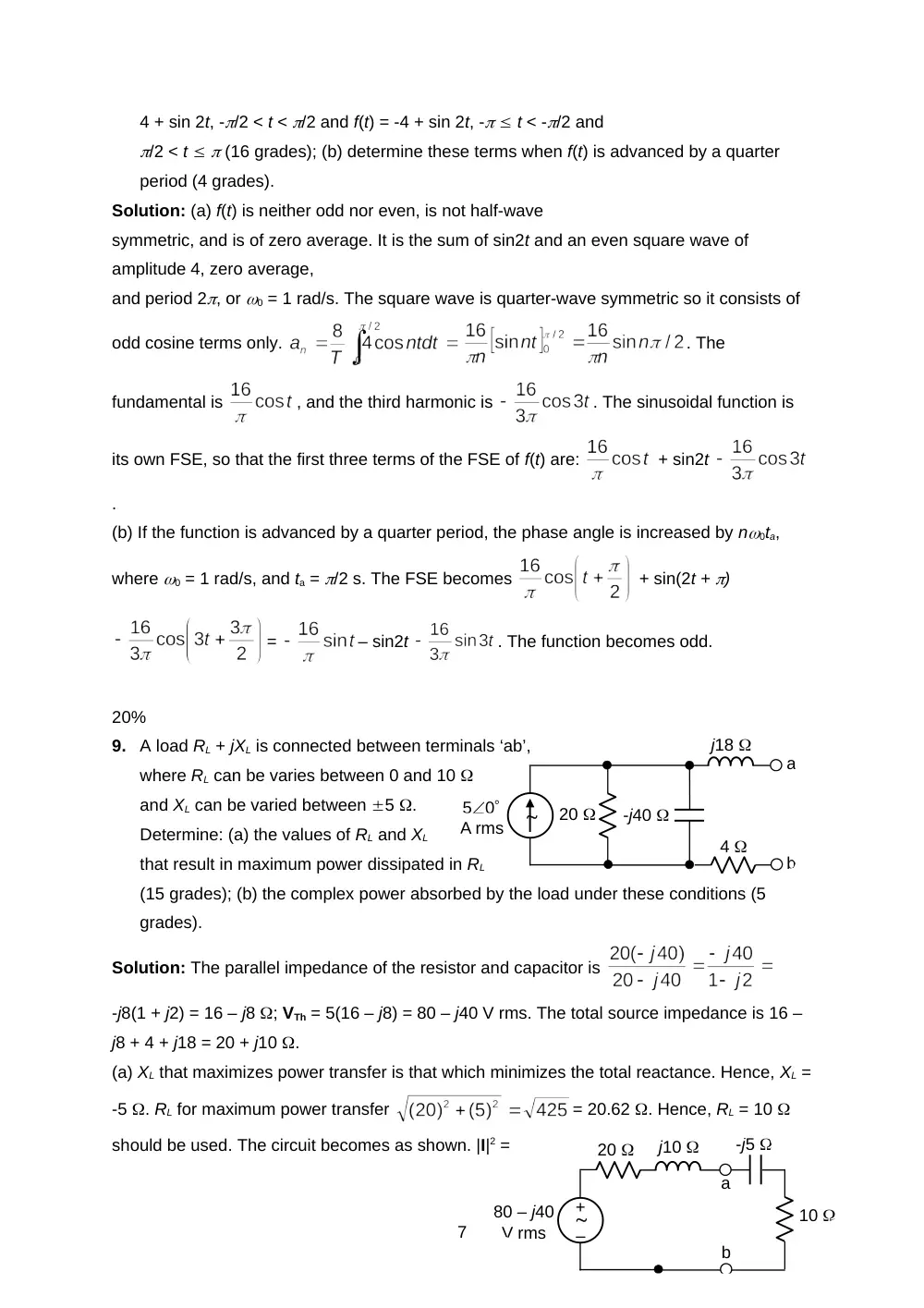
A load RL + jXL is connected between terminals ‘ab’,
where RL can be varies between 0 and 10
and XL can be varied between 5 .
Determine: (a) the values of RL and XL
that result in maximum power dissipated in RL
(15 grades); (b) the complex power absorbed by the load under these conditions (5
grades).
Solution: The parallel impedance of the resistor and capacitor is
-j8(1 + j2) = 16 – j8 ; VTh = 5(16 – j8) = 80 – j40 V rms. The total source impedance is 16 –
j8 + 4 + j18 = 20 + j10 .
(a) XL that maximizes power transfer is that which minimizes the total reactance. Hence, XL =
-5 . RL for maximum power transfer
= 20.62 . Hence, RL = 10
should be used. The circuit becomes as shown. |I|2 =
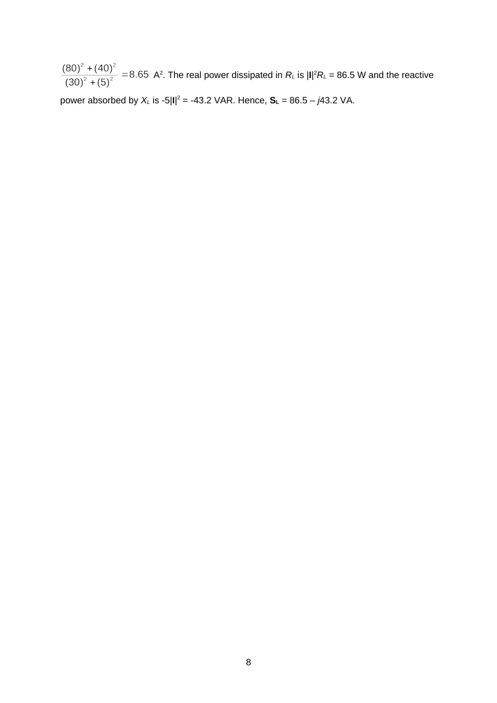
7
A2. The real power dissipated in RL is |I|2RL = 86.5 W and the reactive
power absorbed by XL is -5|I|2 = -43.2 VAR. Hence, SL = 86.5 – j43.2 VA.
8