
EECE 290 Exam 3 with Solution, Spring 2016
American University of Beirut · Analog Signal Processing · 6 pages · with solution


More EECE 290 files
- Exam 1 Clean Copy · Spring 2019ExamView
- Exam 2 Clean Copy · Spring 2019ExamView
- Exam 1 with Solutions · Spring 2019Exam · with solutionView
- Exam 2 with Solutions · Spring 2018Exam · with solutionView
- Exam 1 with Solutions · Spring 2018Exam · with solutionView
- Exam 1 Quiz 1 2016 · Spring 2017ExamView
- Exam 2 Quiz 2 2016 · Spring 2017ExamView
- Exam 1 · Spring 2017ExamView
Show the text of this exam
–
+
vSRC
1 F
1
–
+
vC
1
t = 0
6 µF
2 µF
+
–
V0
2
2
-2
A
1
-1
t
t
EECE 290
Quiz 3, Apr 16, 2016
4% (Primal Question)
A. Determine vC(t), t 0+, assuming vSRC(t) = (t) V and the
capacitor to be initially uncharged.
Solution: If the impulse is K(t) V, it will cause a current
impulse of K(t) A through the capacitor, depositing a charge of
K C on the capacitor and resulting in vC(0+) = K V; = 0.5 s, so that
V, t is in s.
Version 1: K = 1,
=
V
Version 2: K = 2,
= 2
V
Version 3: K = 3,
= 3
V
Version 4: K = 4,
= 4
V
Version 5: K = 5,
= 5
V.
4% (Primal Question)
B. The switch is closed at t = 0, with the 2 F capacitor initially
charged to V0 = 2 V, and the 6 F capacitor uncharged.
Determine the common voltage across the capacitors at t = 0+,
and the strength of the impulse that flows.
Solution: The initial capacitor charge is 2V0 C, and the final voltage is 2V0/8 = V0/4 V. The
charge on the 6 F capacitor is 1.5V0 C, which is the strength of the current impulse.
Version 1: V0 = 2 V, v(0+) = V0/4 = 0.5 V, q = 1.5V0 = 3 C
Version 2: V0 = 4 V, v(0+) = V0/4 = 1 V, q = 1.5V0 = 6 C
Version 3: V0 = 6 V, v(0+) = V0/4 = 1.5 V, q = 1.5V0 = 9 C
Version 4: V0 = 8 V, v(0+) = V0/4 = 2 V, q = 1.5V0 = 12 C
Version 5: V0 = 10 V, v(0+) = V0/4 = 2.5 V, q = 1.5V0 = 15 C.
4% (Primal Question)
C. Determine the maximum value of the convolution
integral when the two pulses are convolved
together, assuming A = 1.
Solution: The maximum area under the product is 2A×2 = 4A.
Version 1: A = 1, ym = 4A = 4
Version 2: A = 1.5, ym = 4A = 6
1
–
+
K(t)
V
1 k
iL
2u(t)
A
1 H
Ku(t)
A
1 F
–
+ 5 V
1 H
2
iR
2 A
Version 3: A = 2, ym = 4A = 8
Version 4: A = 2.5, ym = 4A = 10
Version 5: A = 3, ym = 4A = 12.
4% (Primal Question)
D. Derive the ILT of
.
Solution: The PFE of
is
. The ILT is A(1 – cost)u(t).
Version 1: A = 1, ILT = A(1 – cost) = (1 – cost)u(t)
Version 2: A = 2, ILT = A(1 – cost) = 2(1 – cost)u(t)
Version 3: A = 3, ILT = A(1 – cost) = 3(1 – cost)u(t)
Version 4: A = 4, ILT = A(1 – cost) = 4(1 – cost)u(t)
Version 5: A = 5, ILT = A(1 – cost) = 5(1 – cost)u(t).
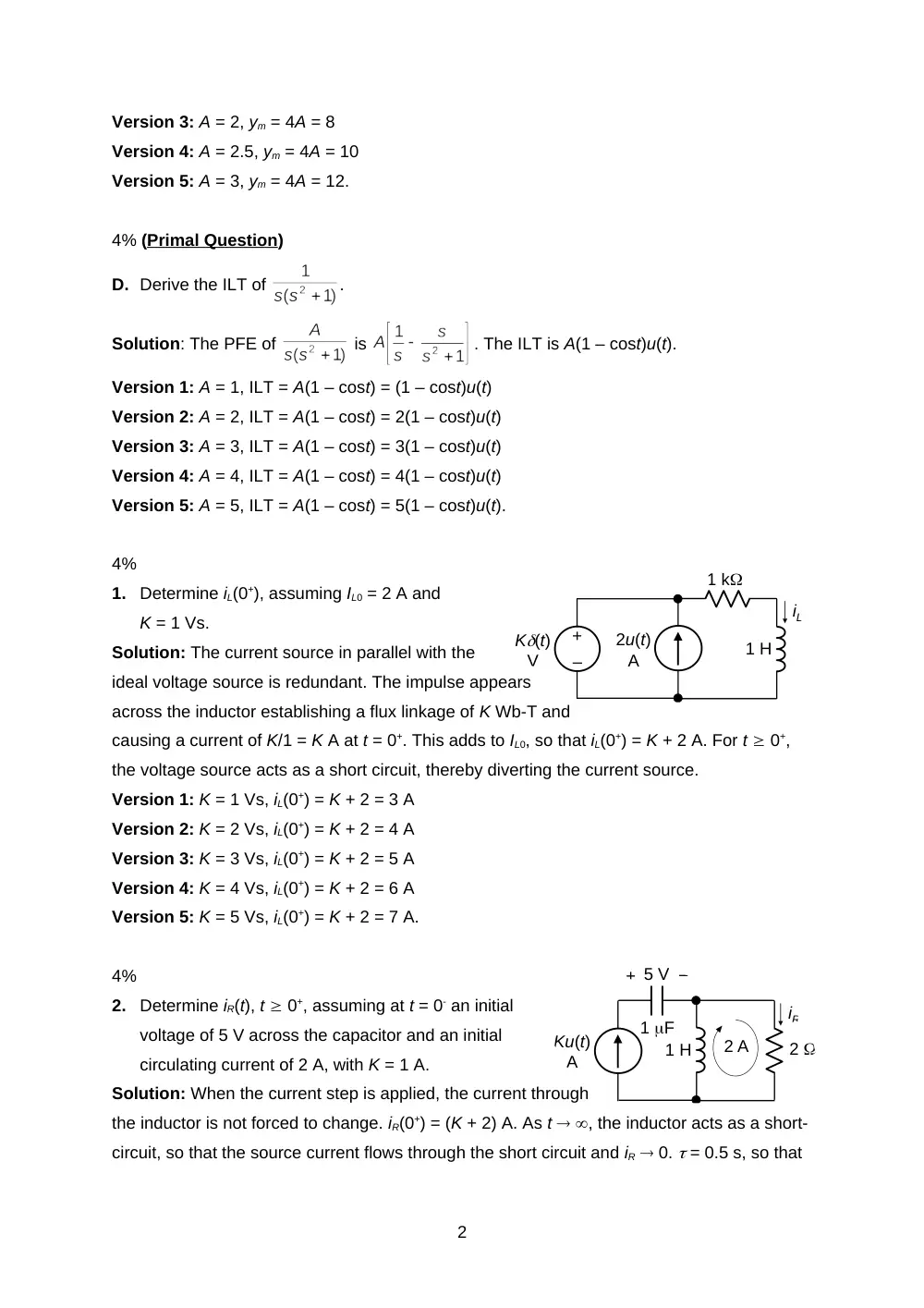
4%
1.
Determine iL(0+), assuming IL0 = 2 A and
K = 1 Vs.
Solution: The current source in parallel with the
ideal voltage source is redundant. The impulse appears
across the inductor establishing a flux linkage of K Wb-T and
causing a current of K/1 = K A at t = 0+. This adds to IL0, so that iL(0+) = K + 2 A. For t 0+,
the voltage source acts as a short circuit, thereby diverting the current source.
Version 1: K = 1 Vs, iL(0+) = K + 2 = 3 A
Version 2: K = 2 Vs, iL(0+) = K + 2 = 4 A
Version 3: K = 3 Vs, iL(0+) = K + 2 = 5 A
Version 4: K = 4 Vs, iL(0+) = K + 2 = 6 A
Version 5: K = 5 Vs, iL(0+) = K + 2 = 7 A.
4%
2.
Determine iR(t), t 0+, assuming at t = 0- an initial
voltage of 5 V across the capacitor and an initial
circulating current of 2 A, with K = 1 A.
Solution: When the current step is applied, the current through
the inductor is not forced to change. iR(0+) = (K + 2) A. As t , the inductor acts as a short-
circuit, so that the source current flows through the short circuit and iR 0. = 0.5 s, so that
2
–
+
K(t)
V
0.5 H
1 F
1
iC
–
+
V0
1 F
1 F
2
2 F
t = 0
–
+
V0
iR
A, t is in s.
Version 1: K = 1 C,
=
A, t is in s
Version 2: K = 2 C,
=
A, t is in s
Version 3: K = 3 C,
=
A, t is in s
Version 4: K = 4 C,
=
A, t is in s
Version 5: K = 5 C,
=
A, t is in s.
4%
3.
Determine iC(0+), assuming no initial current in the
inductor, an initial V0 = 1 V, and K = 1 Vs.
Solution: Initially, the inductor acts as an open circuit,
the capacitor voltage is not forced to change at t = 0+, and an
initial current of 1 A flows downwards through the resistor. The voltage impulse appears
across the inductor, establishing a flux linkage of K Wb-T and causing a current of 2K A to
flow through the inductor. It follows that iC(0+) = (2K – 1) A.
Version 1: K = 1 Vs, iC(0+) = (2K – 1) = 1 A
Version 2: K = 2 Vs, iC(0+) = (2K – 1) = 3 A
Version 3: K = 3 Vs, iC(0+) = (2K – 1) = 5 A
Version 4: K = 4 Vs, iC(0+) = (2K – 1) = 7 A
Version 5: K = 5 Vs, iC(0+) = (2K – 1) = 9 A.
4%
4.
Determine iR(t), t 0+, assuming an initial voltage
V0 = 4 V, and no initial charge in the other two
capacitors.
Solution: When the switch is closed, the voltages across
the
two 1 F capacitors are forced to become equal, that across
the 2
F is not forced to change because of iR, which is finite. Charge is conserved between the
two 1 F capacitors at t = 0+, so that the voltage across them at t = 0+ is V0/2 V. iR(0+) = (V0/4)
A. The equivalent capacitance in series with the resistor is 1 F, so that = 2 s. Hence,
A, t in s.
Version 1: V0 = 4 V,
=
A, t in s
Version 2: V0 = 8 V,
=
A, t in s
Version 3: V0 = 12 V,
=
A, t in s
Version 4: V0 = 16 V,
=
A, t in s
3
4
2
-2
f(t)
t
A
1
-1
f(t)
t
A/2
1
-1
f(1)(t)
t
-A(t)
Version 5: V0 = 20 V,
=
A, t in s.
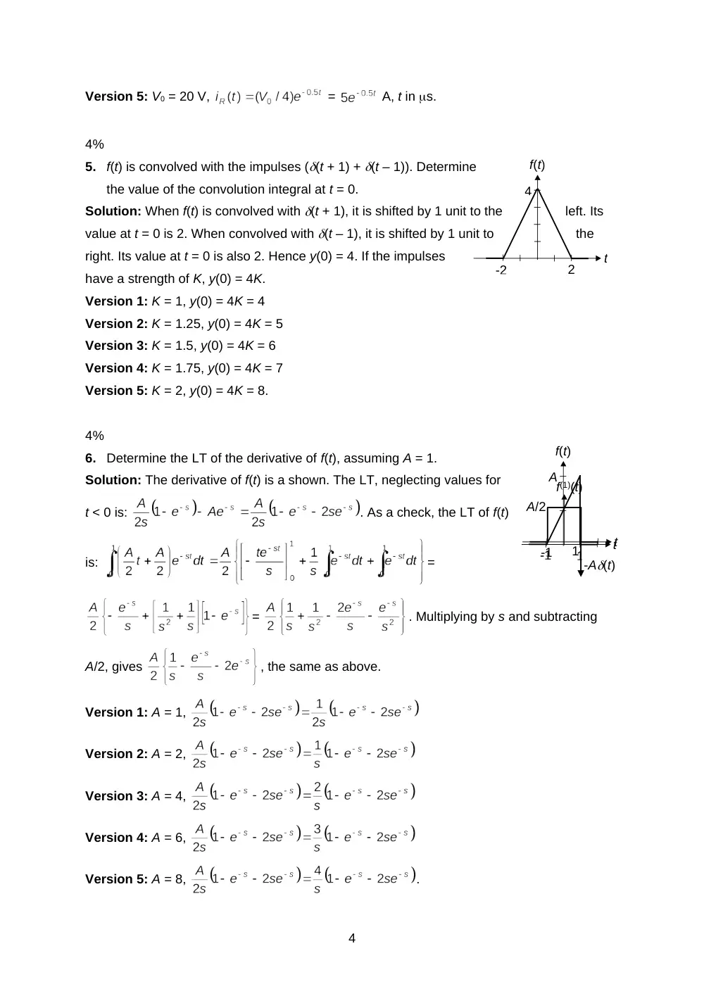
4%
5.
f(t) is convolved with the impulses ((t + 1) + (t – 1)). Determine
the value of the convolution integral at t = 0.
Solution: When f(t) is convolved with (t + 1), it is shifted by 1 unit to the
left. Its
value at t = 0 is 2. When convolved with (t – 1), it is shifted by 1 unit to
the
right. Its value at t = 0 is also 2. Hence y(0) = 4. If the impulses
have a strength of K, y(0) = 4K.
Version 1: K = 1, y(0) = 4K = 4
Version 2: K = 1.25, y(0) = 4K = 5
Version 3: K = 1.5, y(0) = 4K = 6
Version 4: K = 1.75, y(0) = 4K = 7
Version 5: K = 2, y(0) = 4K = 8.
4%
6.
Determine the LT of the derivative of f(t), assuming A = 1.
Solution: The derivative of f(t) is a shown. The LT, neglecting values for
t < 0 is:
. As a check, the LT of f(t)
is:
=
=
. Multiplying by s and subtracting
A/2, gives
, the same as above.
Version 1: A = 1,
Version 2: A = 2,
Version 3: A = 4,
Version 4: A = 6,
Version 5: A = 8,
.
4
1
1
-1
-1
t
t+1
1
1
-1
-1
1-t
t
t - 1
1
1
-1
-1
t
t - 1
2-t
2
+v2 –
–
+v3
–
+
v1
t = 0
C1
C2
C3
1
1
1
-1
-1
f(t)
g(t)
t, s
t, s
1
20%
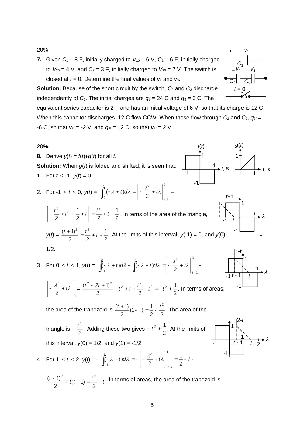
7.
Given C1 = 8 F, initially charged to V10 = 6 V, C2 = 6 F, initially charged
to V20 = 4 V, and C3 = 3 F, initially charged to V30 = 2 V. The switch is
closed at t = 0. Determine the final values of v2 and v3.
Solution: Because of the short circuit by the switch, C2 and C3 discharge
independently of C1. The initial charges are q2 = 24 C and q3 = 6 C. The
equivalent series capacitor is 2 F and has an initial voltage of 6 V, so that its charge is 12 C.
When this capacitor discharges, 12 C flow CCW. When these flow through C2 and C3, q3f =
-6 C, so that v3f = -2 V, and q2f = 12 C, so that v2f = 2 V.
20%
8.
Derive y(t) = f(t)g(t) for all t.
Solution: When g(t) is folded and shifted, it is seen that:
1.
For t -1, y(t) = 0
2.
For -1 t 0, y(t) =
. In terns of the area of the triangle,
y(t) =
. At the limits of this interval, y(-1) = 0, and y(0)
=
1/2.
3.
For 0 t 1, y(t) =
=
. In terms of areas,
the area of the trapezoid is
. The area of the
triangle is
. Adding these two gives
. At the limits of
this interval, y(0) = 1/2, and y(1) = -1/2.
4.
For 1 t 2, y(t) =
. In terms of areas, the area of the trapezoid is
5
–
+
vSRC
1 F
1
iSRC
–
+
VC0
. At the limits of this interval, y(1) = -1/2, and y(2) = 0.
5.
For t 2, y(t) = 0.
20%
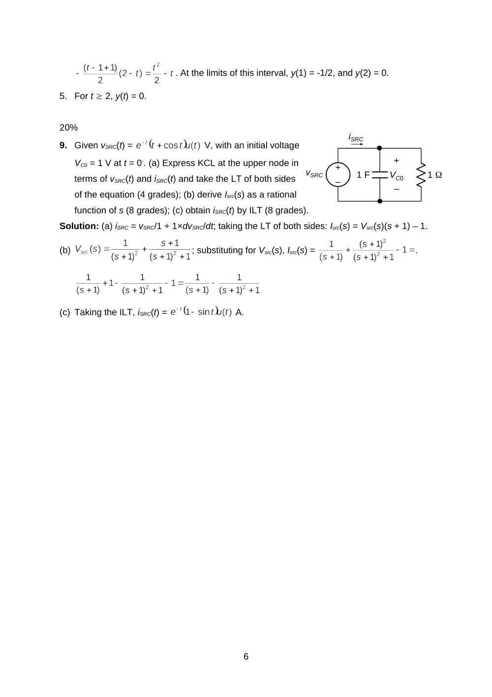
9.
Given vSRC(t) =
V, with an initial voltage
VC0 = 1 V at t = 0-. (a) Express KCL at the upper node in
terms of vSRC(t) and iSRC(t) and take the LT of both sides
of the equation (4 grades); (b) derive Isrc(s) as a rational
function of s (8 grades); (c) obtain iSRC(t) by ILT (8 grades).
Solution: (a) iSRC = vSRC/1 + 1×dvSRC/dt; taking the LT of both sides: Isrc(s) = Vsrc(s)(s + 1) – 1.
(b)
; substituting for Vsrc(s), Isrc(s) =
.
(c) Taking the ILT, iSRC(t) =
A.
6