
EECE 290 Homework 1 with Solution, Spring 2011
American University of Beirut · Analog Signal Processing · 5 pages · with solution


More EECE 290 files
- Homework 1 To 14 · Spring 2016HomeworkView
- Homework 13 · Spring 2015HomeworkView
- Homework 1 · Spring 2015HomeworkView
- Homework 10 · Spring 2015HomeworkView
- Homework 11 · Spring 2015HomeworkView
- Homework 12 · Spring 2015HomeworkView
- Homework 14 · Spring 2015HomeworkView
- Homework 15 · Spring 2015HomeworkView
Show the text of this homework
1
Homework 1
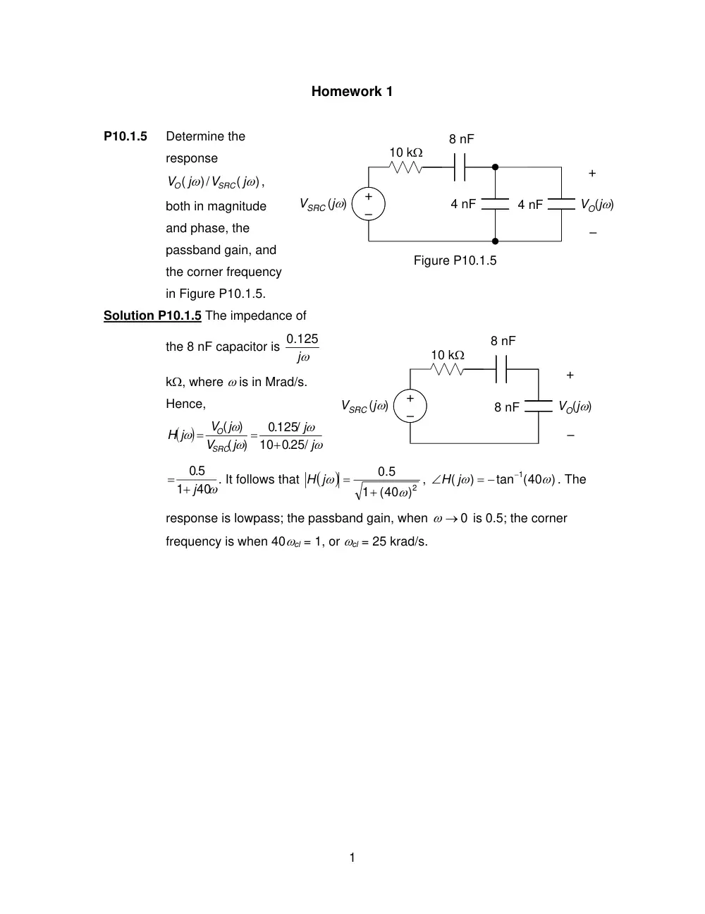
P10.1.5
Determine the
response
)
(
/)
(
ω
ω
j
V
j
V
SRC
O
,
both in magnitude
and phase, the
passband gain, and
the corner frequency
in Figure P10.1.5.
Solution P10.1.5 The impedance of
the 8 nF capacitor is
jω
0.125
kΩ, where ω is in Mrad/s.
Hence,
(
)
ω
ω
ω
ω
ω
j
j
j
V
V j
j
H
SRC
O
.0 25/
10
.0 125/
)
(
)
(
+
=
=
ω
40
1
5.0
= + j
. It follows that
(
)
2)
(40
1
.5
0
ω
ω
+
=
H j
,
tan (40 )
)
(
1
ω
ω
−
= −
∠
H j
. The
response is lowpass; the passband gain, when
ω → 0
is 0.5; the corner
frequency is when 40ωcl = 1, or ωcl = 25 krad/s.
–
+
+
–
10 kΩ
8 nF
8 nF
VO(jω)
VSRC (jω)
Figure P10.1.5
–
+
4 nF
+
–
10 kΩ
4 nF
8 nF
VO(jω)
VSRC (jω)
2
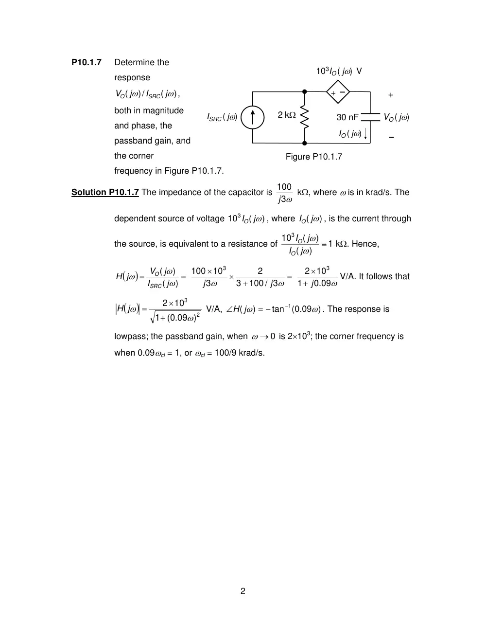
P10.1.7
Determine the
response
)
(
/)
(
ω
ω
j
I
j
V
SRC
O
,
both in magnitude
and phase, the
passband gain, and
the corner
frequency in Figure P10.1.7.
Solution P10.1.7 The impedance of the capacitor is
3ω
100
j
kΩ, where ω is in krad/s. The
dependent source of voltage
)
(
103
IO jω
, where
( ω)
IO j
, is the current through
the source, is equivalent to a resistance of
1
)
(
)
(
103
≡
ω
ω
j
I
j
I
O
O
kΩ. Hence,
(
)
=
=
)
(
)
(
ω
ω
ω
j
I
j
V
j
H
SRC
O
=
+
×
×
ω
ω
100 / 3
3
2
3
10
100
3
j
j
0.09ω
1
10
2
3
+ j
×
V/A. It follows that
(
)
2
3
(0.09 )
1
10
2
ω
ω
+
×
=
H j
V/A,
(0.09 )
tan
)
(
1
ω
ω
−
= −
∠
H j
. The response is
lowpass; the passband gain, when
ω → 0
is 2×10³; the corner frequency is
when 0.09ωcl = 1, or ωcl = 100/9 krad/s.
Figure P10.1.7
30 nF
IO ( jω)
103IO ( jω) V
–
+
2 kΩ
ISRC ( jω)
+
–
VO ( jω)
3
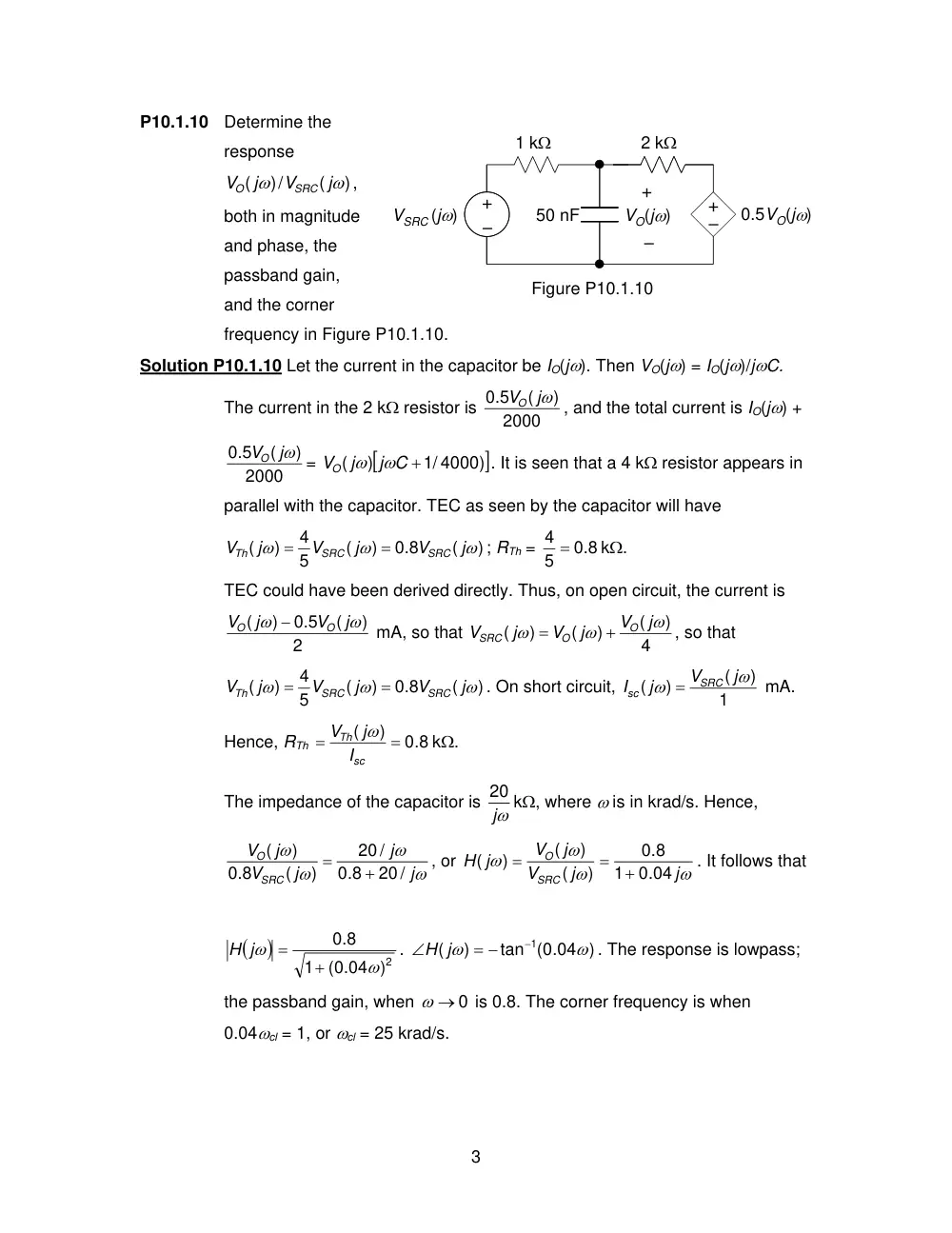
P10.1.10 Determine the
response
)
(
/)
(
ω
ω
j
V
j
V
SRC
O
,
both in magnitude
and phase, the
passband gain,
and the corner
frequency in Figure P10.1.10.
Solution P10.1.10 Let the current in the capacitor be IO(jω). Then VO(jω) = IO(jω)/jωC.
The current in the 2 kΩ resistor is
2000
)
(
0.5
VO jω
, and the total current is IO(jω) +
2000
)
(
0.5
VO jω
=
[
1/ 4000 ])
)
(
j C +
VO j
ω
ω
. It is seen that a 4 kΩ resistor appears in
parallel with the capacitor. TEC as seen by the capacitor will have
)
(
0.8
)
(
5
4
)
(
ω
ω
ω
j
V
j
V
j
V
SRC
SRC
Th
=
=
; RTh =
0.8
5
4 =
kΩ.
TEC could have been derived directly. Thus, on open circuit, the current is
2
)
(
0.5
)
(
ω
ω
j
V
j
V
O
O
−
mA, so that
4
)
(
)
(
)
(
ω
ω
ω
j
V
j
V
j
V
O
O
SRC
+
=
, so that
)
(
0.8
)
(
5
4
)
(
ω
ω
ω
j
V
j
V
j
V
SRC
SRC
Th
=
=
. On short circuit,
1
)
(
)
(
ω
ω
j
V
j
I
SRC
sc
=
mA.
Hence, RTh
0.8
)
(
=
=
sc
Th
I
j
V
ω
kΩ.
The impedance of the capacitor is ω
j
20 kΩ, where ω is in krad/s. Hence,
ω
ω
ω
ω
j
j
j
V
j
V
SRC
O
20 /
0.8
20 /
)
(
0.8
)
(
+
=
, or
ω
ω
ω
ω
j
j
V
j
V
j
H
SRC
O
0.04
1
0.8
)
(
)
(
)
(
+
=
=
. It follows that
(
)
2)
(0.04
1
.8
0
ω
ω
+
=
H j
.
tan (0.04 )
)
(
1
ω
ω
−
= −
∠
H j
. The response is lowpass;
the passband gain, when
ω → 0
is 0.8. The corner frequency is when
0.04ωcl = 1, or ωcl = 25 krad/s.
Figure P10.1.10
–
+
1 kΩ
+
–
50 nF
2 kΩ
–
+
VO(jω)
0.5VO(jω)
VSRC (jω)
4
P10.1.12 Determine the response
)
(
/)
(
ω
ω
j
V
j
V
SRC
O
, both
in magnitude and
phase, the passband
gain, and the corner
frequency in Figure
P10.1.12.
Solution P10.1.12 The impedance
of the capacitor is
10 9
100
1
−
×
jω
jω
≡ 10
kΩ,
where ω is in krad/s.
When the source and 2
kΩ resistor are reflected to the secondary side, they become a source of
2VSRC(jω) in series with 8 kΩ. Hence,
ω
ω
ω
j
j
V
j
V
SRC
O
10 /
18
10
)
(
2
)
(
+
=
, or
ω
ω
ω
ω
ω
ω
1.8
1
2
10 /
18
20
)
(
)
(
)
(
j
j
j
j
V
j
V
j
H
SRC
O
+
=
+
=
=
. It follows that
(
)
2)
(1.8
1
2
ω
ω
ω
+
=
H j
,
tan (1.8 )
90
)
(
1
ω
ω
−
−
=
∠
o
H j
. The response is
highpass; the passband gain, when
ω → ∞
is 10/9 ≡ 0.915 dB; the corner
frequency is ωcl = 9
5 krad/s ≡ 88.4 Hz
10 kΩ
2 kΩ
–
+
100 nF
1:2
+
–
VO ( jω)
VSRC ( jω)
10 kΩ
Figure P10.1.12
2 kΩ
–
+
100 nF
1:2
+
–
VO(jω)
VSRC (jω)
5
P10.2.2
Determine R , L , and
C in Figure P10.2.2
such that:
(a) the maximum
response of VO(s) is 1
V; (b) the bandwidth is
4 krad/s; and (c) the center frequency is 100 krad/s.
P10.2.2 Maximum response, which occurs at ω0, is RI; hence R = 10 kΩ. Q =
Solution
ω0 /BW = 100/4 = 25; it follows that
≡
×
=
=
4
5
0
10
10
25
R
Q
C
ω
25 nF, and L =
4
25 10
10
5
4
0
≡
×
Q =
R
ω
mH.
P10.2.3
Given the transfer function
125
500
5
100
1000
4
)
(
2
2
+
+
+
+
=
s
s
s
s
H s
. Determine the
maximum response in dB.
Solution P10.2.3.
⎥
⎦
⎤
⎢
⎣
⎡
+
+
+
+
+
+
⎥ =
⎦
⎤
⎢
⎣
⎡
+
+
+
+
=
25
100
250
25
100
25
0.8
25
100
25
250
5
4
)
(
2
2
2
2
2
s
s
s
s
s
s
s
s
s
s
H s
.
The first term is a bandstop response of magnitude 0.8 at low and high
frequencies and zero at ω = 5 rad/ s. The second term is a bandpass
response of zero at low and high frequencies and magnitude of 2 at ω = 5
rad/ s. The sum will have a maximum magnitude of 2, or 20log102 = 6 dB, at
ω = 5 rad/s.
Figure P10.2.2
C
L
+
–
VO(s)
0.1 mA
R