
EECE 290 Homework 2, Spring 2015
American University of Beirut · Analog Signal Processing · 4 pages


More EECE 290 files
- Homework 1 To 14 · Spring 2016HomeworkView
- Homework 12 · Spring 2015HomeworkView
- Homework 1 · Spring 2015HomeworkView
- Homework 15 · Spring 2015HomeworkView
- Homework 10 · Spring 2015HomeworkView
- Homework 11 · Spring 2015HomeworkView
- Homework 13 · Spring 2015HomeworkView
- Homework 14 · Spring 2015HomeworkView
Show the text of this homework
30 nF
IO ( j)
103IO ( j) V
–
+
2 k
ISRC ( j)
+
–
VO ( j)
Figure P14.1.15
Homework 2
P14.1.4
Given a lowpass RL filter having R = 1 k and L = 20 mH. Determine: (a) the 3-
dB cutoff frequency in krad/s; (b) the lowpass transfer function.
Short solution: (a) c = R/L = 1000/(2010-3) rad/s 1000/20 = 50 krad/s.
(b) For the LP response, . If frequency is expressed as in krad/s, then H(j) = .
P14.1.14
(a) Determine NEC seen by the resistor in
Figure P14.1.14; (b) IO(j); (c) the 3-dB
cutoff frequency.
Solution: It is convenient to determine the open-
circuit voltage and ZTh. On open circuit, each branch
has an impedance of j1.5, so that the 6 A divides
equally between the two branches. It follows that Vac
= j3; Vbc = j1.5; Vba = VTh = Vbc – Vac = j1.5 – j3 =
-j1.5. When the current source is replaced by an
open circuit, the impedance between terminals ‘ab’ is
j1.5 in parallel with j1.5, which is j0.75. TEC will
be as shown. Hence, NEC consists of a current
source IN = Iba =
-j1.5/(j0.75) = -2 A in parallel with j0.75, as shown. The current source -
2 A is directed from terminal ‘b’ to terminal ‘a’ in accordance with the
assumed polarity of VTh.
(b) It follows that = .
(c) ; ; , or, c =4000/3 rad/s 4/3
krad/s.
P14.1.15
Determine, for the filter in
Figure
P14.1.15, (a) the transfer
function VO(j)/ISRC(j);
(b) the 3-dB cutoff
frequency in krad/s;
(c) the magnitude of the gain
1 H
1 H
0.5 H
0.5 H
1 k
6 A
IO(j)
Figure P14.1.14
j
6 A
j
j0.5
a
b
3
j0.5
3
c
j0.75
–
+
-j1.5
b
a
j0.75
-2 A
b
a
1 k
IO(j)
1/6 F 6
1/30 F 30
–
+
VSRC ( j)
Figure P14.1.20
1 F
30 nF
103IO(j) V
+ –
+
–
–
+
VO(j)
IO(j)
IT(j)
VT(j)
+
–
–
+
3
100
j
k
3 k
VO(j)
2103ISRC(j)
and the phase angle as a function of frequency; (d) the maximum gain in the
passband.
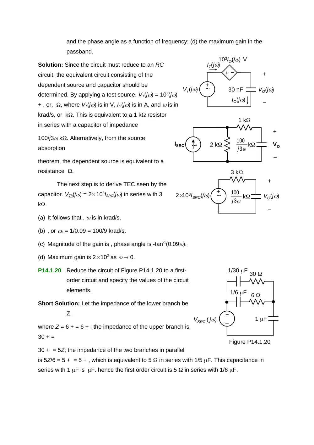
Solution: Since the circuit must reduce to an RC
circuit, the equivalent circuit consisting of the
dependent source and capacitor should be
determined. By applying a test source, VT(j) = 103(j)
+ , or, , where VT(j) is in V, IO(j) is in A, and is in
krad/s, or k. This is equivalent to a 1 k resistor
in series with a capacitor of impedance
100/j3 k. Alternatively, from the source
absorption
theorem, the dependent source is equivalent to a
resistance .
The next step is to derive TEC seen by the
capacitor. VTh(j) = 2103ISRC(j) in series with 3
k.
(a) It follows that , is in krad/s.
(b) , or c = 1/0.09 = 100/9 krad/s.
(c) Magnitude of the gain is , phase angle is -tan-1(0.09).
(d) Maximum gain is 2103 as 0.
P14.1.20
Reduce the circuit of Figure P14.1.20 to a first-
order circuit and specify the values of the circuit
elements.
Short Solution: Let the impedance of the lower branch be
Z,
where Z = 6 + = 6 + ; the impedance of the upper branch is
30 + =
30 + = 5Z; the impedance of the two branches in parallel
is 5Z/6 = 5 + = 5 + , which is equivalent to 5 in series with 1/5 F. This capacitance in
series with 1 F is F. hence the first order circuit is 5 in series with 1/6 F.
2 k
ISRC
+
–
VO
1 k
3
100
j
k
1/jC
R2
R1
jL
–
+
Figure P14.1.22
VSRC ( j)
I2 ( j)
I1 ( j)
Figure P14.2.8
–
+
VSRC ( j)
R
0.5 F
L
+
–
VO (j)
Figure P14.2.9
–
+
VSRC ( j)
0.5 F
2 H
+
–
VO (j)
60
30
5
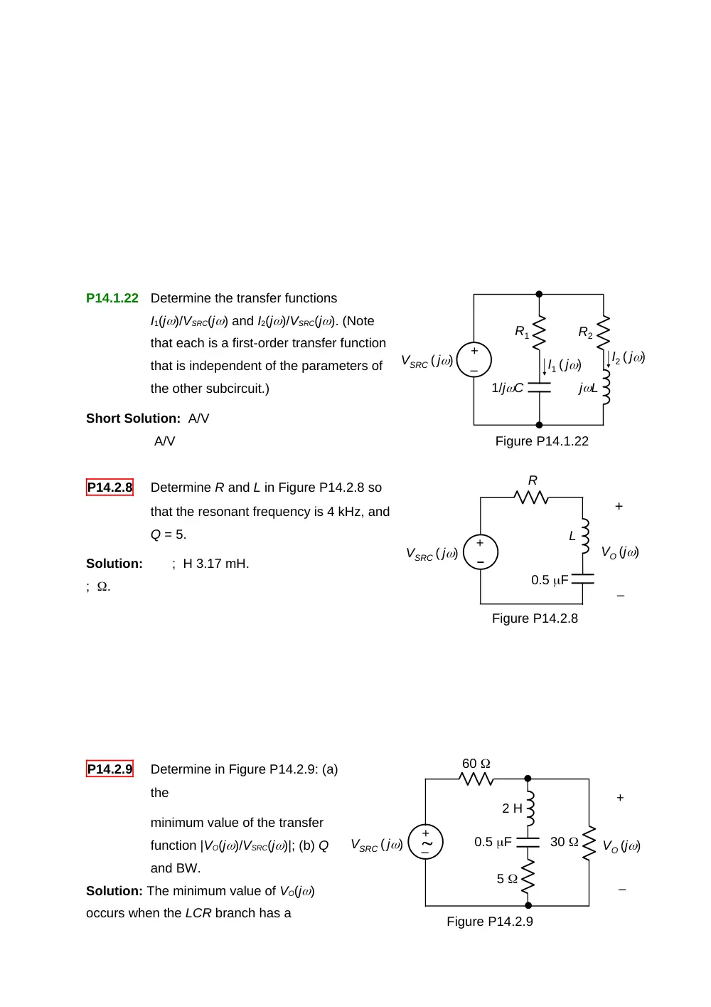
P14.1.22
Determine the transfer functions
I1(j)/VSRC(j) and I2(j)/VSRC(j). (Note
that each is a first-order transfer function
that is independent of the parameters of
the other subcircuit.)
Short Solution: A/V
A/V
P14.2.8
Determine R and L in Figure P14.2.8 so
that the resonant frequency is 4 kHz, and
Q = 5.
Solution:
; H 3.17 mH.
; .
P14.2.9
Determine in Figure P14.2.9: (a)
the
minimum value of the transfer
function |VO(j)/VSRC(j)|; (b) Q
and BW.
Solution: The minimum value of VO(j)
occurs when the LCR branch has a
minimum impedance. This occurs when L and C in series have a zero impedance, that is, at
= 103 rad/s. At this frequency, 30||5 = 30/7 .
(a) From voltage division, the minimum value of the transfer function .
(b) TEC seen by the LCR branch has RTh = (60)||(30) = 20 . For the purpose of determining
Q, VTh can be set to zero, the circuit reducing to that shown. This is a series LCR circuit
with R = 25 . Hence, 80; BW = 12.5 rad/s.
P14.2.15
Determine the frequency at
which VO(j) = 0 in Figure
P14.2.15
Solution: VO(j) = 0 when the
impedance of the LC branch is zero.
The impedance of L in parallel with C is
. This impedance in series with -j/C =
0, that is, , which gives , or , or rad/s Mrad/s.
Figure P14.2.15
1 H
+
–
VO (j)
ISRC(j)
1 F
1 F
10 k