
EECE 290 Homework 2 with Solution, Spring 2011
American University of Beirut · Analog Signal Processing · 5 pages · with solution
More EECE 290 files
- Homework 1 To 14 · Spring 2016HomeworkView
- Homework 12 · Spring 2015HomeworkView
- Homework 1 · Spring 2015HomeworkView
- Homework 15 · Spring 2015HomeworkView
- Homework 10 · Spring 2015HomeworkView
- Homework 11 · Spring 2015HomeworkView
- Homework 13 · Spring 2015HomeworkView
- Homework 14 · Spring 2015HomeworkView
Show the text of this homework
1
Homework 2
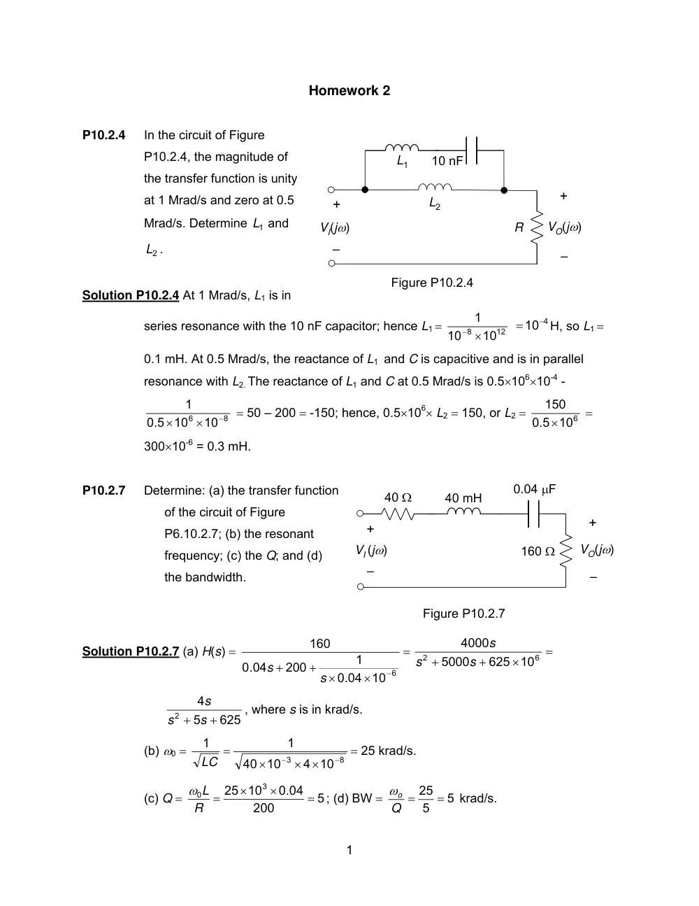
P10.2.4
In the circuit of Figure
P10.2.4, the magnitude of
the transfer function is unity
at 1 Mrad/s and zero at 0.5
Mrad/s. Determine
1
L and
2
L .
Solution P10.2.4 At 1 Mrad/s, L1 is in
series resonance with the 10 nF capacitor; hence L1 =
12
8
10
10
1
− ×
=10−4
H, so L1 =
0.1 mH. At 0.5 Mrad/s, the reactance of L1 and C is capacitive and is in parallel
resonance with L2. The reactance of L1 and C at 0.5 Mrad/s is 0.5×106×10-4 -
8
6
10
0.5 10
1
−
×
×
= 50 – 200 = -150; hence, 0.5×10⁶× L2 = 150, or L2 =
0.5 106
150
×
=
300×10-6 = 0.3 mH.
P10.2.7
Determine: (a) the transfer function
of the circuit of Figure
P6.10.2.7; (b) the resonant
frequency; (c) the Q; and (d)
the bandwidth.
Solution P10.2.7 (a) H(s) =
=
×
×
+
+
0.04 10−6
1
200
.04
0
160
s
s
=
×
+
+
6
2
10
625
5000
4000
s
s
s
625
5
4
2
s + s +
s
, where s is in krad/s.
(b) ω0 =
8
3
4 10
10
40
1
1
−
−
×
×
×
=
LC
= 25 krad/s.
(c) Q =
5
200
0.04
10
25
3
0
=
×
×
=
R
ω L
; (d) BW =
5
5
= 25 =
Q
ωo
krad/s.
Figure P10.2.4
10 nF
L1
+
–
VO(jω)
+
–
VI(jω)
R
L2
Figure P10.2.7
40 Ω
0.04 μF
40 mH
160 Ω
+
–
VO(jω)
+
–
VI (jω)
2
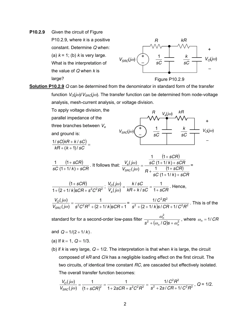
P10.2.9
Given the circuit of Figure
P10.2.9, where k is a positive
constant. Determine Q when:
(a) k = 1; (b) k is very large.
What is the interpretation of
the value of Q when k is
large?
Solution P10.2.9 Q can be determined from the denominator in standard form of the transfer
function VO(jω)/VSRC(jω). The transfer function can be determined from node-voltage
analysis, mesh-current analysis, or voltage division.
To apply voltage division, the
parallel impedance of the
three branches between Va
and ground is:
(
) =
+
+
+
sC
k
kR
k sC
sC kR
/)1
(
/
1/
(
)
sCR
k
sCR
sC
+
+
+
)
(1 1/
1
1
. It follows that:
(
)
(
)
sCR
k
sCR
sC
R
sCR
k
sCR
sC
j
V
j
V
SRC
a
+
+
+
+
+
+
+
=
)
(1 1/
1
1
)
(1 1/
1
1
)
(
)
(
ω
ω
=
(
)
(
)
2
2 2
1/
2
1
1
s C R
k sCR
sCR
+
+
+
+
;
sCR
k sC
kR
k sC
j
V
j
V
a
O
+
=
+
=
1
1
/
/
)
(
)
(
ω
ω
. Hence,
(
)
1
1/
2
1
)
(
)
(
2
2 2
+
+
+
=
k sCR
s C R
j
V
j
V
SRC
O
ω
ω
=
(
)
2
2
2
2
2
1/
/
1/
2
1/
C R
k s CR
s
C R
+
+
+
. This is of the
standard for for a second-order low-pass filter
(
)
2
2
2
/
n
n
n
Q s
s
ω
ω
ω
+
+
, where
CR
n
= 1/
ω
and
)
1/
1/(2
k
Q
+
=
.
(a) If k = 1, Q = 1/3.
(b) if k is very large, Q = 1/2. The interpretation is that when k is large, the circuit
composed of kR and C/k has a negligible loading effect on the first circuit. The
two circuits, of identical time constant RC, are cascaded but effectively isolated.
The overall transfer function becomes:
(
)
=
+
+
=
+
=
2
2
2
2
2
1
1
1
1
)
(
)
(
s C R
sCR
sCR
j
V
j
V
SRC
O
ω
ω
2
2
2
2
2
1/
2 /
1/
C R
s CR
s
C R
+
+
, Q = 1/2.
R
kR
sC
1
sC
k
Figure P10.2.9
+
–
VO(jω)
–
+
VSRC(jω)
R
kR
sC
1
sC
k
+
–
VO(jω)
–
+
VSRC(jω)
Va(jω)
3
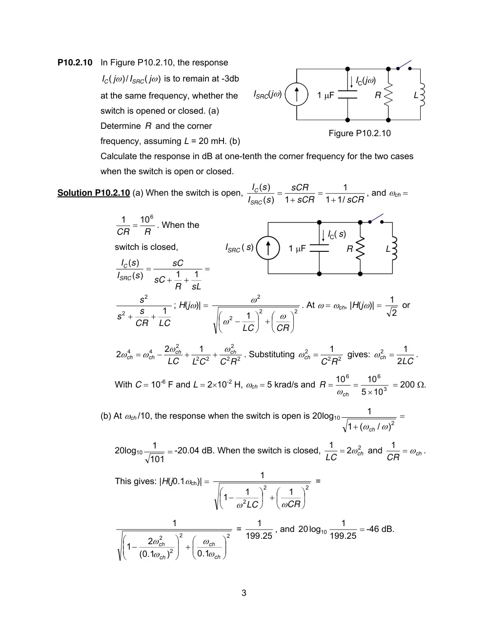
P10.2.10 In Figure P10.2.10, the response
)
(
/)
(
ω
ω
j
I
j
I
SRC
C
is to remain at -3db
at the same frequency, whether the
switch is opened or closed. (a)
Determine R and the corner
frequency, assuming L = 20 mH. (b)
Calculate the response in dB at one-tenth the corner frequency for the two cases
when the switch is open or closed.
Solution P10.2.10 (a) When the switch is open,
sCR
sCR
sCR
s
I
s
I
SRC
C
1/
1
1
1
( )
( )
+
=
+
=
, and ωch =
R
CR
1 = 106
. When the
switch is closed,
=
+
+
=
sL
R
sC
sC
s
I
s
I
SRC
C
1
1
( )
)
(
LC
CR
s
s
s
1
2
2
+
+
; H(jω)| =
2
2
2
2
1
⎟
⎠
⎞
⎜
⎝
⎟ + ⎛
⎠
⎞
⎜
⎝
⎛
−
CR
LC
ω
ω
ω
. At ω = ωch, |H(jω)| =
2
1 or
2
2
2
2
2
2
4
4
1
2
2
C R
L C
LC
ch
ch
ch
ch
ω
ω
ω
ω
+
+
−
=
. Substituting
2
2
2
1
C R
ωch =
gives:
LC
ch
2
1
ω2 =
.
With C = 10-6 F and L = 2×10⁻² H, ωch = 5 krad/s and
3
6
6
10
5
10
10
×
=
=
ch
R
ω
= 200 Ω.
(b) At ωch /10, the response when the switch is open is 20log10
2)
/
(
1
1
ωch ω
+
=
20log10
=
101
1
-20.04 dB. When the switch is closed,
2 2
1
ch
LC
= ω
and
ch
CR
1 = ω
.
This gives: |H(j0.1ωch)| =
2
2
2
1
1
1
1
⎟
⎠
⎞
⎜
⎝
⎟ + ⎛
⎠
⎞
⎜
⎝
⎛ −
CR
LC
ω
ω
=
2
2
2
2
0.1
)
(0.1
2
1
1
⎟⎟
⎠
⎞
⎜⎜
⎝
⎟⎟ + ⎛
⎠
⎞
⎜⎜
⎝
⎛ −
ch
ch
ch
ch
ω
ω
ω
ω
=
199.25
1
, and
199.25 =
1
20log
10
-46 dB.
R
ISRC ( s)
L
1 μF
IC( s)
R
ISRC(jω)
L
1 μF
IC(jω)
Figure P10.2.10
4
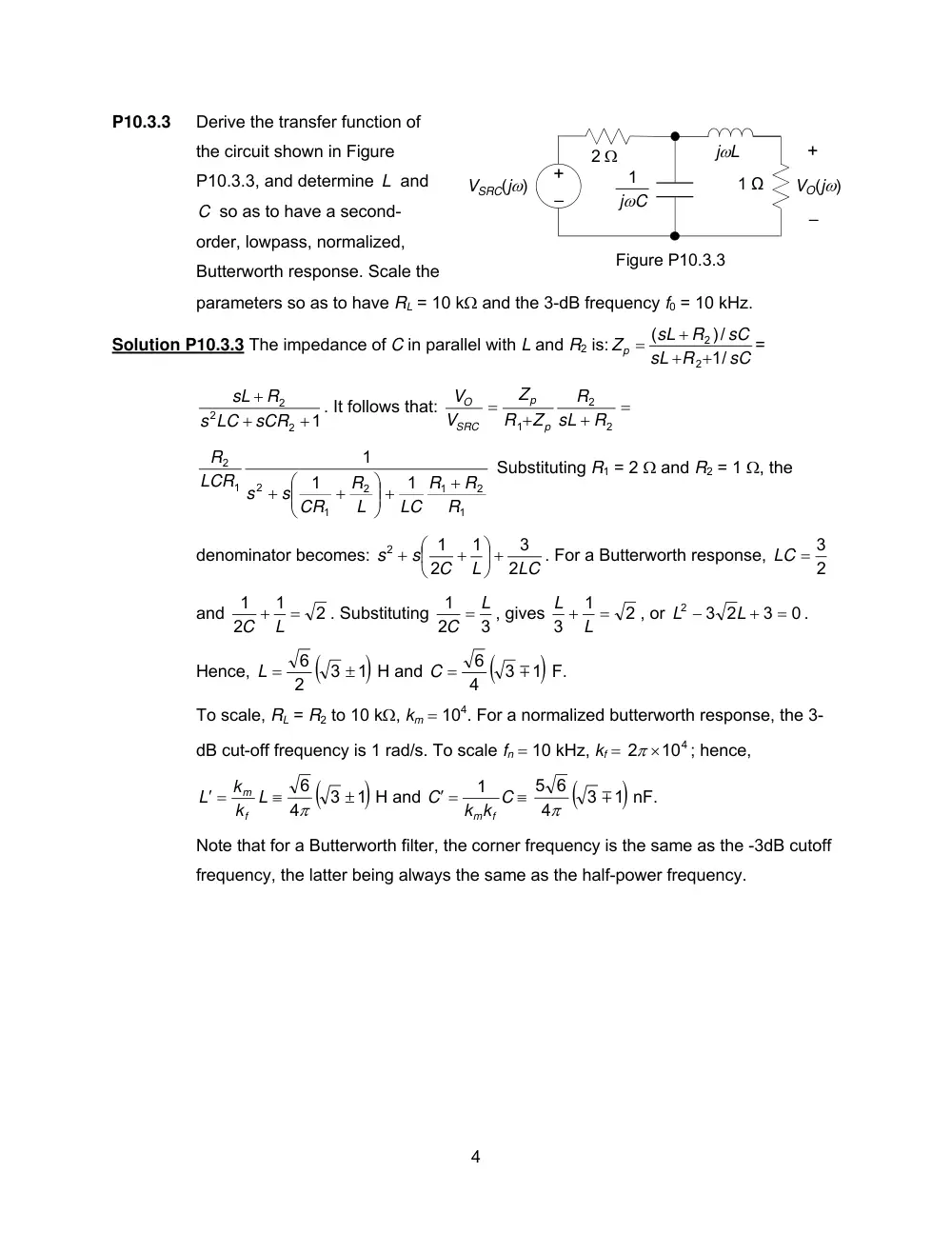
P10.3.3
Derive the transfer function of
the circuit shown in Figure
P10.3.3, and determine L and
C so as to have a second-
order, lowpass, normalized,
Butterworth response. Scale the
parameters so as to have RL = 10 kΩ and the 3-dB frequency f0 = 10 kHz.
Solution P10.3.3 The impedance of C in parallel with L and R2 is:
sC
sL R
sC
R
sL
Zp
1/
/)
(
2
2
+
+
+
=
=
1
2
2
2
+
+
+
sCR
s LC
R
sL
. It follows that:
=
+
+
=
2
2
1
R
sL
R
Z
R
Z
V
V
p
p
SRC
O
1
2
1
2
1
2
1
2
1
1
1
R
R
R
LC
L
R
s CR
LCR s
R
+
⎟⎟ +
⎠
⎞
⎜⎜
⎝
⎛
+
+
Substituting R1 = 2 Ω and R2 = 1 Ω, the
denominator becomes:
s2 +
LC
L
C
s
2
3
1
2
1
⎟ +
⎠
⎞
⎜
⎝
⎛
+
. For a Butterworth response,
2
LC = 3
and
2
1
2
1
C + L =
. Substituting
3
2
1
C = L
, gives
2
1
3
L + L =
, or
0
3
2
3
2
=
+
−
L
L
.
Hence,
(
)1
3
2
6
±
L =
H and
(
)1
3
4
6
m
C =
F.
To scale, RL = R2 to 10 kΩ, km = 104. For a normalized butterworth response, the 3-
dB cut-off frequency is 1 rad/s. To scale fn = 10 kHz, kf =
2 ×10⁴
π
; hence,
≡
′ =
L
k
k
L
f
m
(
)1
3
4
6
±
π
H and
k k C
C
f
m
1
′ =
≡
(
)1
3
4
5 6
m
π
nF.
Note that for a Butterworth filter, the corner frequency is the same as the -3dB cutoff
frequency, the latter being always the same as the half-power frequency.
Figure P10.3.3
+
–
VO(jω)
2 Ω
–
+
VSRC(jω)
jωC
1
jωL
1 Ω
5
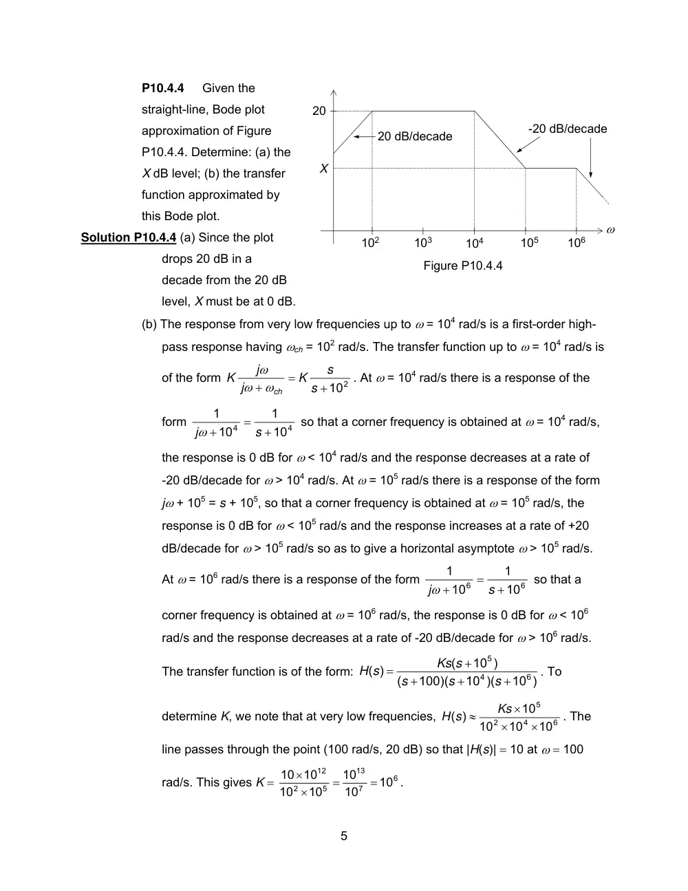
P10.4.4
Given the
straight-line, Bode plot
approximation of Figure
P10.4.4. Determine: (a) the
X dB level; (b) the transfer
function approximated by
this Bode plot.
Solution P10.4.4 (a) Since the plot
drops 20 dB in a
decade from the 20 dB
level, X must be at 0 dB.
(b) The response from very low frequencies up to ω = 104 rad/s is a first-order high-
pass response having ωch = 102 rad/s. The transfer function up to ω = 104 rad/s is
of the form
+102
=
+
s
s
K
j
j
K
ωch
ω
ω
. At ω = 104 rad/s there is a response of the
form
4
4
10
1
10
1
+
=
+
s
jω
so that a corner frequency is obtained at ω = 104 rad/s,
the response is 0 dB for ω < 104 rad/s and the response decreases at a rate of
-20 dB/decade for ω > 104 rad/s. At ω = 105 rad/s there is a response of the form
jω + 105 = s + 105, so that a corner frequency is obtained at ω = 105 rad/s, the
response is 0 dB for ω < 105 rad/s and the response increases at a rate of +20
dB/decade for ω > 105 rad/s so as to give a horizontal asymptote ω > 105 rad/s.
At ω = 106 rad/s there is a response of the form
6
6
10
1
10
1
+
=
+
s
jω
so that a
corner frequency is obtained at ω = 106 rad/s, the response is 0 dB for ω < 106
rad/s and the response decreases at a rate of -20 dB/decade for ω > 106 rad/s.
The transfer function is of the form:
10 )
10 )(
100)(
(
10 )
(
)
(
6
4
5
+
+
+
+
=
s
s
s
Ks s
H s
. To
determine K, we note that at very low frequencies,
6
4
2
5
10
10
10
10
( )
×
×
×
≈
Ks
H s
. The
line passes through the point (100 rad/s, 20 dB) so that |H(s)| = 10 at ω = 100
rad/s. This gives K =
6
7
13
5
2
12
10
10
10
10
10
10 10
=
=
×
×
.
Figure P10.4.4
ω
102
103
104
105
106
20
X
-20 dB/decade
20 dB/decade