
EECE 290 Homework 3, Spring 2015
American University of Beirut · Analog Signal Processing · 5 pages



More EECE 290 files
- Homework 1 To 14 · Spring 2016HomeworkView
- Homework 12 · Spring 2015HomeworkView
- Homework 1 · Spring 2015HomeworkView
- Homework 15 · Spring 2015HomeworkView
- Homework 10 · Spring 2015HomeworkView
- Homework 11 · Spring 2015HomeworkView
- Homework 13 · Spring 2015HomeworkView
- Homework 14 · Spring 2015HomeworkView
Show the text of this homework
Figure P14.2.6
C
L
+
–
VO (j)
0.1 mA
R
Figure P14.2.7
1 mH
VSRC (j)
1 k
1 F
–
+
0.9VSRCj)
–
+
Figure P14.2.7
VSRC(j)
1 k
–
+
–
+
IC(j)
jL
1/jC
0.9VSRC(j)
+ 0.1VSRC(j) –
Homework 3
P14.2.6
Determine R, L, and C In
Figure P14.2.6 so that the
maximum response is 1 V,
0 = 100 krad/s, and BW
= 4 krad/s.
Short Solution: maximum response occurs when the
combined impedance of L and C is infinite. The source current flows through R. so that:
R(0.1 mA) = 1 V, which gives R = 10 k.
From the given data, Q = 0/BW = 100/4 = 25 = 0CR, so that C = 25/(0R) =
25/(105104) = 2510-9 F 25 nF.
Since , or, H 4 mH.
P14.2.7
Determine 0 and Q in
Figure
P14.2.7.
Solution: The first step is to
account for the dependent source.
The voltage across the
capacitor is 0.1 VSRC(j). Hence,
(0.1VSRC(j))(jC) =
VSRC(j)j(0.1C).
In other words, the capacitor C in
series
with the dependent source is
equivalent to a capacitor 0.1C.
This is in
accordance with the source absorption
theorem, for the current through the dependent
source is VSRC(j)j(0.1C). Dividing this by the voltage 0.9VSRC, the dependent source is
equivalent to an admittance jC/9, or a capacitor C/9. This capacitor in series with C gives a
capacitance C(C/9)/(C + C/9) = 0.1C.
+
–
VO ( j)
750
50 H
20 nF
VSRC ( j)
–
+
Figure P14.2.10
+
–
VO ( j)
40 k
100 mH
100 nF
VSRC ( j)
–
+
Figure P14.2.12
10 k
It follows that rad/s 100 krad/s. Q = 0RC =
10510-7103 = 10.
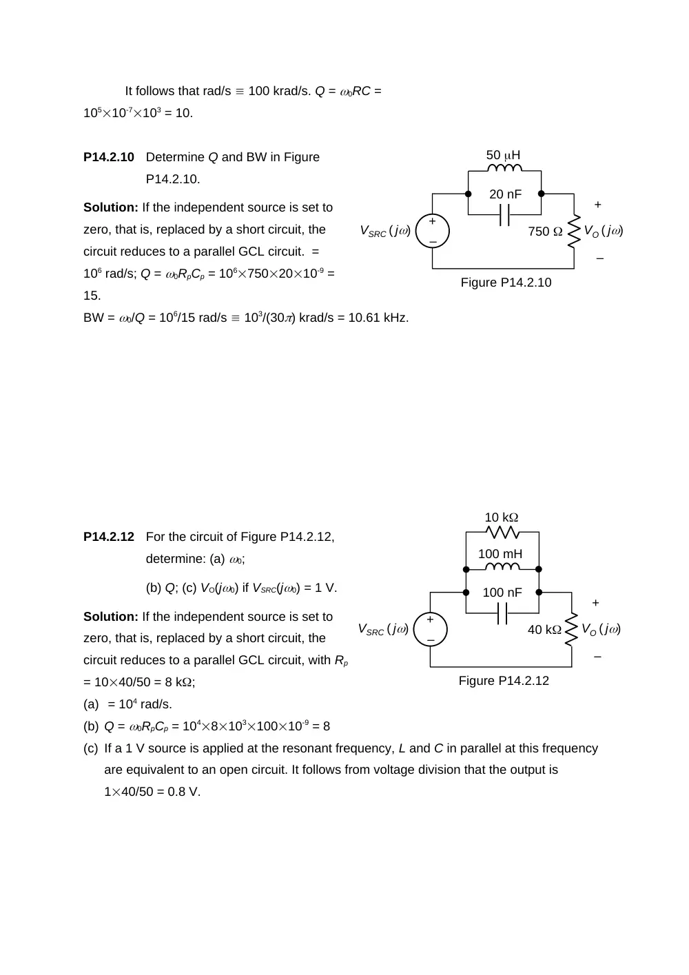
P14.2.10
Determine Q and BW in Figure
P14.2.10.
Solution: If the independent source is set to
zero, that is, replaced by a short circuit, the
circuit reduces to a parallel GCL circuit. =
106 rad/s; Q = 0RpCp = 1067502010-9 =
15.
BW = 0/Q = 106/15 rad/s 103/(30) krad/s = 10.61 kHz.
P14.2.12
For the circuit of Figure P14.2.12,
determine: (a) 0;
(b) Q; (c) VO(j0) if VSRC(j0) = 1 V.
Solution: If the independent source is set to
zero, that is, replaced by a short circuit, the
circuit reduces to a parallel GCL circuit, with Rp
= 1040/50 = 8 k;
(a) = 104 rad/s.
(b) Q = 0RpCp = 104810310010-9 = 8
(c) If a 1 V source is applied at the resonant frequency, L and C in parallel at this frequency
are equivalent to an open circuit. It follows from voltage division that the output is
140/50 = 0.8 V.
Figure P14.2.13
–
+
VSRC ( j)
R
L
+
– VO (j)
C
R
L
C
Figure P14.2.17
1 k
+
–
VO (j)
1 F
1 F
–
+
VSRC ( j)
1 k
–
+
R
sL
+
– VO(j)
1/sC
R
a
b
c
sL
1/sC
VSRC(j)
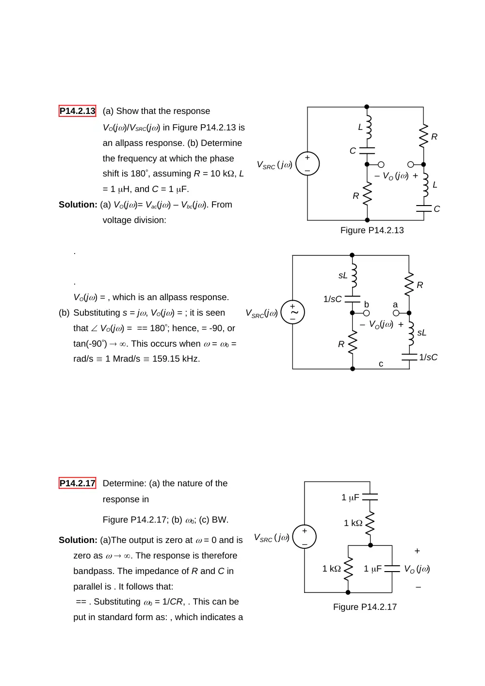
P14.2.13
(a) Show that the response
VO(j)/VSRC(j) in Figure P14.2.13 is
an allpass response. (b) Determine
the frequency at which the phase
shift is 180, assuming R = 10 k, L
= 1 H, and C = 1 F.
Solution: (a) VO(j)= Vac(j) – Vbc(j). From
voltage division:
.
.
VO(j) = , which is an allpass response.
(b) Substituting s = j, VO(j) = ; it is seen
that VO(j) = == 180; hence, = -90, or
tan(-90) . This occurs when = 0 =
rad/s 1 Mrad/s 159.15 kHz.
P14.2.17
Determine: (a) the nature of the
response in
Figure P14.2.17; (b) 0; (c) BW.
Solution: (a)The output is zero at = 0 and is
zero as . The response is therefore
bandpass. The impedance of R and C in
parallel is . It follows that:
== . Substituting 0 = 1/CR, . This can be
put in standard form as: , which indicates a
20log10|H(j)|, dB
0
-20
2
25
250
20log10|H(j)|, dB
0
20
-20
2
25
250
Figure P14.3.8
Q = 1/3 and a maximum gain of 1/3.
(b) 0 = 1/CR = 1/(10-6103) = 103 rad/s 1 krad/s.
(c) BW = 0/Q = 1/(1/3) = 3 krad/s.
P14.3.3
Given . Determine the smaller 3-db cutoff frequency.
Short Solution: , BW = 50 = 2 – 1; ; = 0; ; 1 = 40 rad/s.
P14.3.8
Determine the transfer function
whose asymptotic Bode magnitude
plot is shown in Figure P14.3.8.
Solution: The first part, as shown, is a
highpass response of corner frequency 2 rad/s.
The transfer function is: =, and . If ,
and 20log10;
if 0, , and 20log10 20log10() – 20log10(2),
which is the equation
of the LF asymptote.
The second part is the mirror image,
with respect to the horizontal axis, of the
low pass response shown, having a corner
frequency 25 rad/s. The transfer function is:
=, and ; if 0, ; 20log10; if , , and
20log1020log10(25) – 20log10(),which is the
equation of the HF asymptote. The transfer
function of the mirror image with respect to the horizontal axis is the reciprocal on a log
scale. The transfer function of the given part is therefore =. The overall Bode plots is the sum
of the Bode plots of the two parts on a log scale, which corresponds to the product of the
20log10|H(j)|, dB
0
-20
2
25
250
transfer functions, that is: .