
EECE 290 Homework 4, Spring 2015
American University of Beirut · Analog Signal Processing · 3 pages
More EECE 290 files
- Homework 1 To 14 · Spring 2016HomeworkView
- Homework 12 · Spring 2015HomeworkView
- Homework 1 · Spring 2015HomeworkView
- Homework 15 · Spring 2015HomeworkView
- Homework 10 · Spring 2015HomeworkView
- Homework 11 · Spring 2015HomeworkView
- Homework 13 · Spring 2015HomeworkView
- Homework 14 · Spring 2015HomeworkView
Show the text of this homework
5 H
100
vO
+
_
–
+
vI
+
_
Figure P15.3.1
20 k
10 k
1 H
1 k
Homework 4
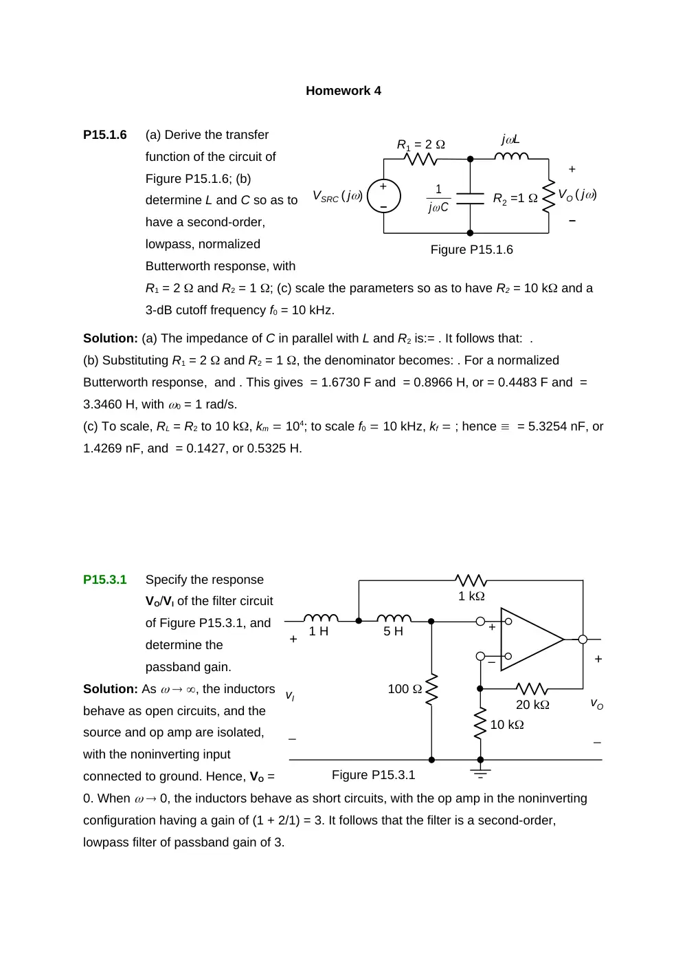
P15.1.6
(a) Derive the transfer
function of the circuit of
Figure P15.1.6; (b)
determine L and C so as to
have a second-order,
lowpass, normalized
Butterworth response, with
R1 = 2 and R2 = 1 ; (c) scale the parameters so as to have R2 = 10 k and a
3-dB cutoff frequency f0 = 10 kHz.
Solution: (a) The impedance of C in parallel with L and R2 is:= . It follows that: .
(b) Substituting R1 = 2 and R2 = 1 , the denominator becomes: . For a normalized
Butterworth response, and . This gives = 1.6730 F and = 0.8966 H, or = 0.4483 F and =
3.3460 H, with 0 = 1 rad/s.
(c) To scale, RL = R2 to 10 k, km 104; to scale f0 10 kHz, kf ; hence = 5.3254 nF, or
1.4269 nF, and = 0.1427, or 0.5325 H.
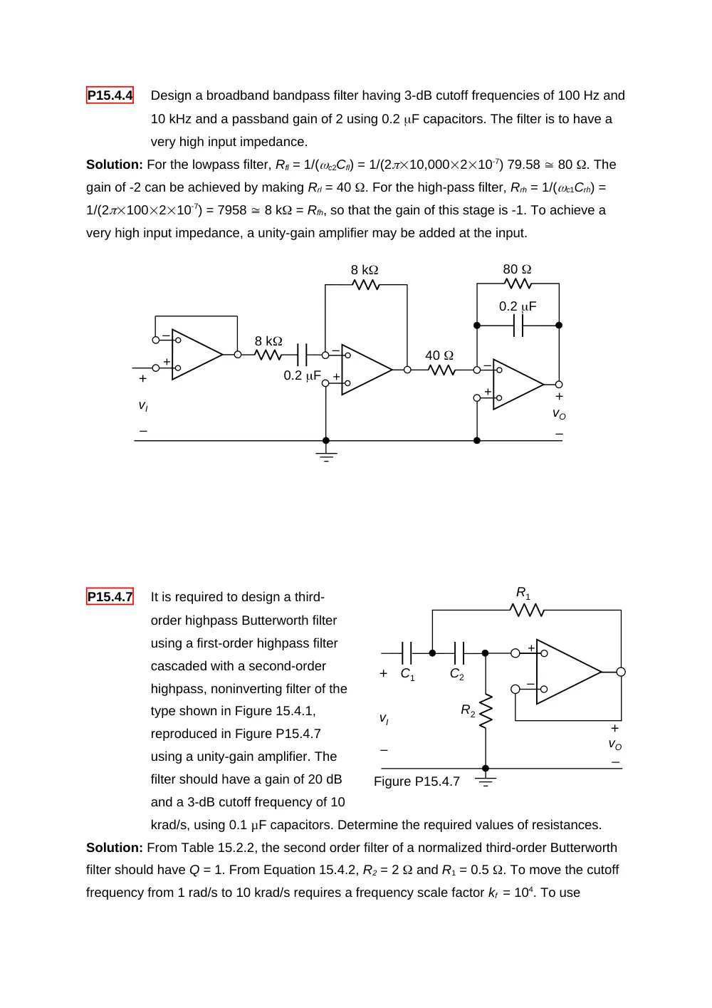
P15.3.1
Specify the response
VO/VI of the filter circuit
of Figure P15.3.1, and
determine the
passband gain.
Solution: As , the inductors
behave as open circuits, and the
source and op amp are isolated,
with the noninverting input
connected to ground. Hence, VO =
0. When 0, the inductors behave as short circuits, with the op amp in the noninverting
configuration having a gain of (1 + 2/1) = 3. It follows that the filter is a second-order,
lowpass filter of passband gain of 3.
+
–
VO ( j)
R1 = 2
–
+
VSRC ( j)
C
j
1
jL
R2 =1
Figure P15.1.6
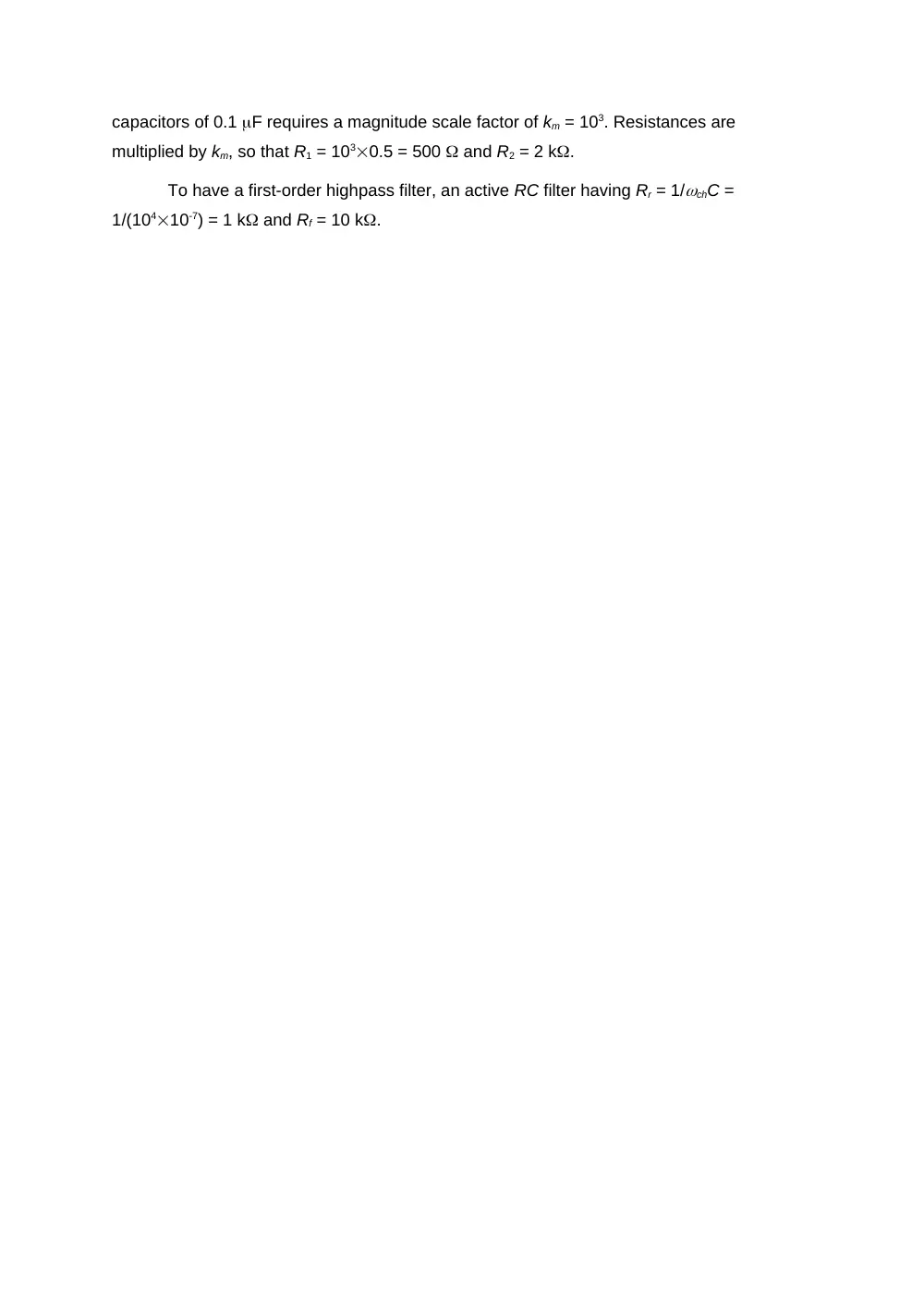
P15.4.4
Design a broadband bandpass filter having 3-dB cutoff frequencies of 100 Hz and
10 kHz and a passband gain of 2 using 0.2 F capacitors. The filter is to have a
very high input impedance.
Solution: For the lowpass filter, Rfl = 1/(c2Cfl) = 1/(210,000210-7) 79.58 80 . The
gain of -2 can be achieved by making Rrl = 40 . For the high-pass filter, Rrh = 1/(c1Crh) =
1/(2100210-7) = 7958 8 k = Rfh, so that the gain of this stage is -1. To achieve a
very high input impedance, a unity-gain amplifier may be added at the input.
P15.4.7
It is required to design a third-
order highpass Butterworth filter
using a first-order highpass filter
cascaded with a second-order
highpass, noninverting filter of the
type shown in Figure 15.4.1,
reproduced in Figure P15.4.7
using a unity-gain amplifier. The
filter should have a gain of 20 dB
and a 3-dB cutoff frequency of 10
krad/s, using 0.1 µF capacitors. Determine the required values of resistances.
Solution: From Table 15.2.2, the second order filter of a normalized third-order Butterworth
filter should have Q = 1. From Equation 15.4.2, R2 = 2 and R1 = 0.5 . To move the cutoff
frequency from 1 rad/s to 10 krad/s requires a frequency scale factor kf = 104. To use
R1
C2
C1
R2
vO
+
_
–
+
Figure P15.4.7
vI
+
–
0.2 F
40
0.2 F
vO
vI
+
–
+
–
–
+
–
+
8 k
8 k
80
–
+
capacitors of 0.1 F requires a magnitude scale factor of km = 103. Resistances are
multiplied by km, so that R1 = 1030.5 = 500 and R2 = 2 k.
To have a first-order highpass filter, an active RC filter having Rr = 1/chC =
1/(10410-7) = 1 k and Rf = 10 k.