
EECE 290 Homework, Spring 2008
American University of Beirut · Analog Signal Processing · 21 pages




Showing the first 10 of 21 pages. Download the PDF to see all of it.
More EECE 290 files
- Homework 1 To 14 · Spring 2016HomeworkView
- Homework 12 · Spring 2015HomeworkView
- Homework 1 · Spring 2015HomeworkView
- Homework 15 · Spring 2015HomeworkView
- Homework 10 · Spring 2015HomeworkView
- Homework 11 · Spring 2015HomeworkView
- Homework 13 · Spring 2015HomeworkView
- Homework 14 · Spring 2015HomeworkView
Show the text of this homework
16.26 The full-wave rectified sine-wave voltage shown in
Fig. P16.26(a) is applied to the circuit shown in
Fig. P16.26(b).
Figure PiG.26
(— ; >)
v4 (V)
340 L
t (s)
0 1/120 1/60 1/40
(a)
Gr
16H
L. 12.5 pF RS i, 3 1kO
Ug(
-O-
(b)
XY wy,
a) Find the first four nonzero terms in the
Fourier series representation of v,.
b), Does your solution for v, make sense? Ex-
plain.
P 16.26 [a] Note — find i,(t)
v-V,
16s
Yo _
1000
1 Vg
1
J, | —— a —6 —_| = —
Vo | +125 x 10 5+ T5099 ls
+ Vo(12.5 x 1078s) +
0
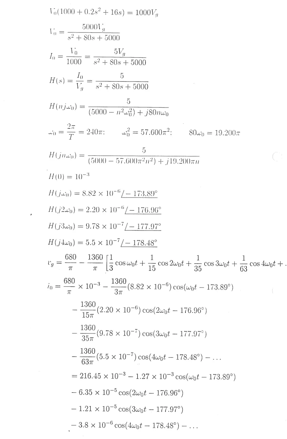
\,,(1000 + 0.2s° + 16s) = 1000V,
—_ 50001,
"52-4 80s + 5000
7, 10 5V,
"1000 s?2 + 80s + 5000
I _
H(s)= = ———
Vy, 82+ 80s + 5000
5
H ;
(V0) = 5 = nae) & SOc
oF oo) 9
<0 = Fe = Hor: wa = 57.6007: SOxvo = 19.2007
5
F( jrey) — 2, T ;
(5000 = 57.60072n2) + j19.200Rn
HU) = 1074
H( jay) = 8.82 x 10⁷°/— 173.89°
A ( j22y) = 2.20 x 10⁷°/— 176.96°
H(j3xy) = 9.78 x 10⁷' /— 177.97°
A (jtuy) = =5.5 x 10⁷ 7 — 178.48°
680 1360 1 1 1
ty = | 3 + coswint + 75 Quyt + 35 COS Swot + 33 cos duit +.
680 1360
ip = x 1077 — (8.82 x 10⁷°) cos(wyt — 173.89°)
Tv oT
1360
— Ep (2:20 x 107%) cos(2uot — 176.96")
Jil
1360
~ 3e (9.78 x 107") cos(3wipt — 177.97°)
O07
_ 1360
637
= 216.45 x 10⁷? — 1.27 x 10⁷? cos(wot — 173.89°)
(5.5 x 1077) cos(4uigt — 178.48°) —
— 6.35 x 10⁷° cos(2upt — 176.96°)
— 1.21 x 10⁷° cos(3wpt — 177.97°)
— 3.8 x 10⁷° cos(4wot — 178.48) —
,
ig = 216.45 — 1.27 cos(wot — 173.89°) mA
Note that the sinusoidal component is very small compared to the de
component, so
ig = 216.45mA (adc current)
[b] Yes, the solution makes sense. The circuit is a low-pass filter which nearly
eliminates all but the dc component.
16.37
a)
b)
Use the first four nonzero terms in the
Fourier series approximation of the peri-
odic voltage shown in Fig. P16.37 to esti-
mate its rms value.
Calculate the true rms value of the voltage.
Calculate the percentage of error in the es-
timated value.
Figure P1G.37
la
v(V)
107 4
2.597
T/4 T/2
37/4
P 16.37 [a] v has half-wave symmetry, quarter-wave symmetry, and is odd
dy = 0, a, = Oall hk. b, = 0 k-even
8 Ts.
== / f(t)sinkuytdt, k-odd
Jo
8 TV “m
== Ul 1 sin hut dt + po J, Sin utah
~ T/8
T/A
T/ ]
— 8Vin cos kwt
4T htuto
T/8 _ 8Vin | COS kwot
'
0 kw
— 8VYn i-e kr 8Vin co hi 0
~ thal | OT | Fh, [O° TF
SVin 1 1 kr ki
= ——— cos + COS
hwoT [4 4 I
Vin 1 a ker
= Tk {5 +0.75c08 7 | [10 + 30 cos kir/-4)]
—
Il
0+ 30cos(a/4) = 31.21
3[10 + 30 cos(3n 7/4)] = —3.74
=
ae
II
|
bs = z {10 + 30 cos(5m/4)| = —2.24
by = =[10 + 30.cos(77/4)] = 4.46
31.212 + 3.742 + 2.242 + 4.467
Vv (rms) = Vj, / + + + = 22.51
5)
2 LT 2
{[b] Area under v- = 2 [2 (2. 5a)? (5 ) +10 “ = §3.1250°T
1
V(ms) = \ 7 (53. 12577)T = V53.1257
22.51
22.90
[c] % Error = ( - 1) (100) = —1.7%
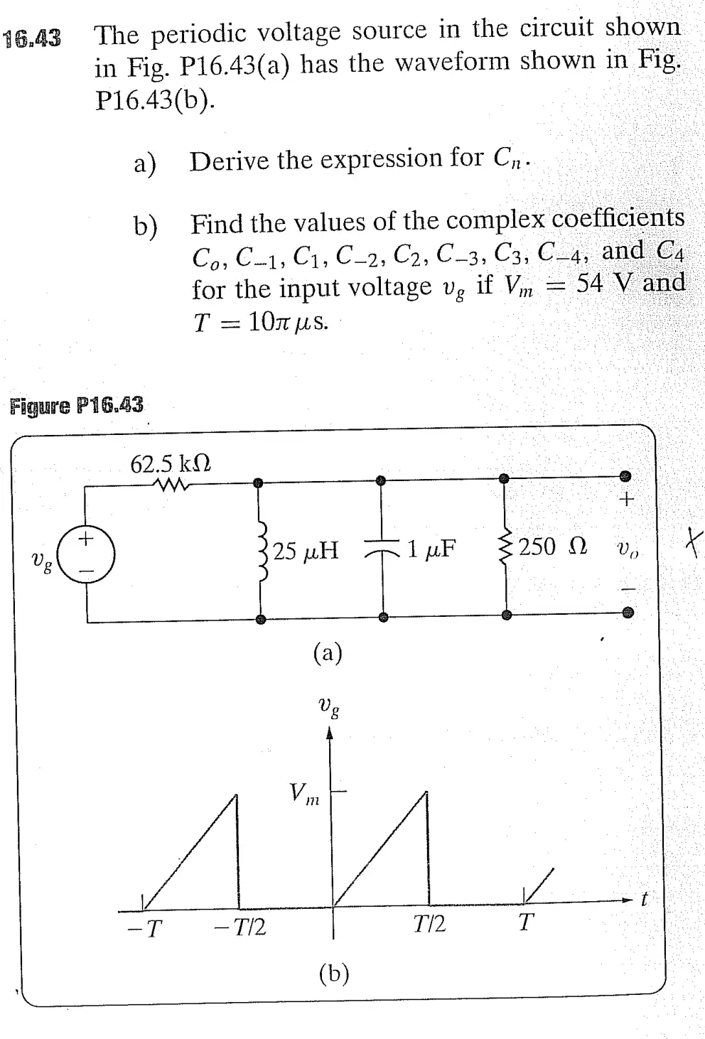
46.43 The periodic voltage source in the circuit shown
in Fig. P16.43(a) has the waveform shown in Fig.
P16.43(b).
a) Derive the expression for Cy.
b) Find the values of the complex coefficients
Co; C1, C1, C_2, C2, C_3, C3, C24; and C4
for the input voltage v, if V, = 54 V and
T = 107 ps.
Figure P16.43
.
62.5 kO
AW- @
| :
+
7@ 25 wH ipF 22509 v, | ¥
il -e
(a) ‘
Ug
A
Vin |
| -t
-T —T/2 T/2 T
b
L (b) J