
EECE 290 Homework, Spring 2008
American University of Beirut · Analog Signal Processing · 14 pages

Showing the first 10 of 14 pages. Download the PDF to see all of it.
More EECE 290 files
- Homework 1 To 14 · Spring 2016HomeworkView
- Homework 12 · Spring 2015HomeworkView
- Homework 1 · Spring 2015HomeworkView
- Homework 15 · Spring 2015HomeworkView
- Homework 10 · Spring 2015HomeworkView
- Homework 11 · Spring 2015HomeworkView
- Homework 13 · Spring 2015HomeworkView
- Homework 14 · Spring 2015HomeworkView
Show the text of this homework
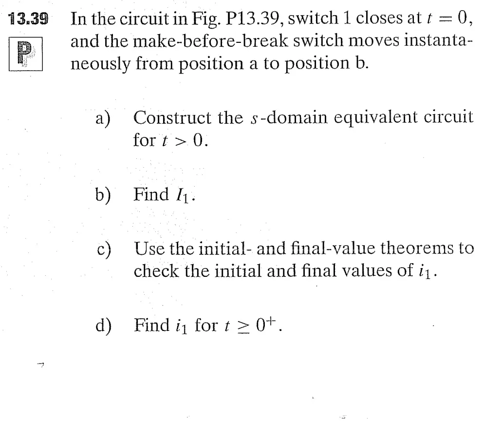
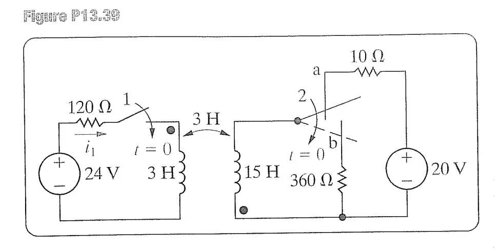
13.39 In the circuit in Fig. P13.39, switch 1 closes at t = 0,
p and the make-before-break switch moves instanta-
neously from position a to position b.
a) Construct the s-domain equivalent circuit
fort > 0.
b) Find k.
c) Use the initial- and final-value theorems to
check the initial and final values of i,.
d) Find i, fort > 0°.
we Te
Ly r=0
(O)av 3H
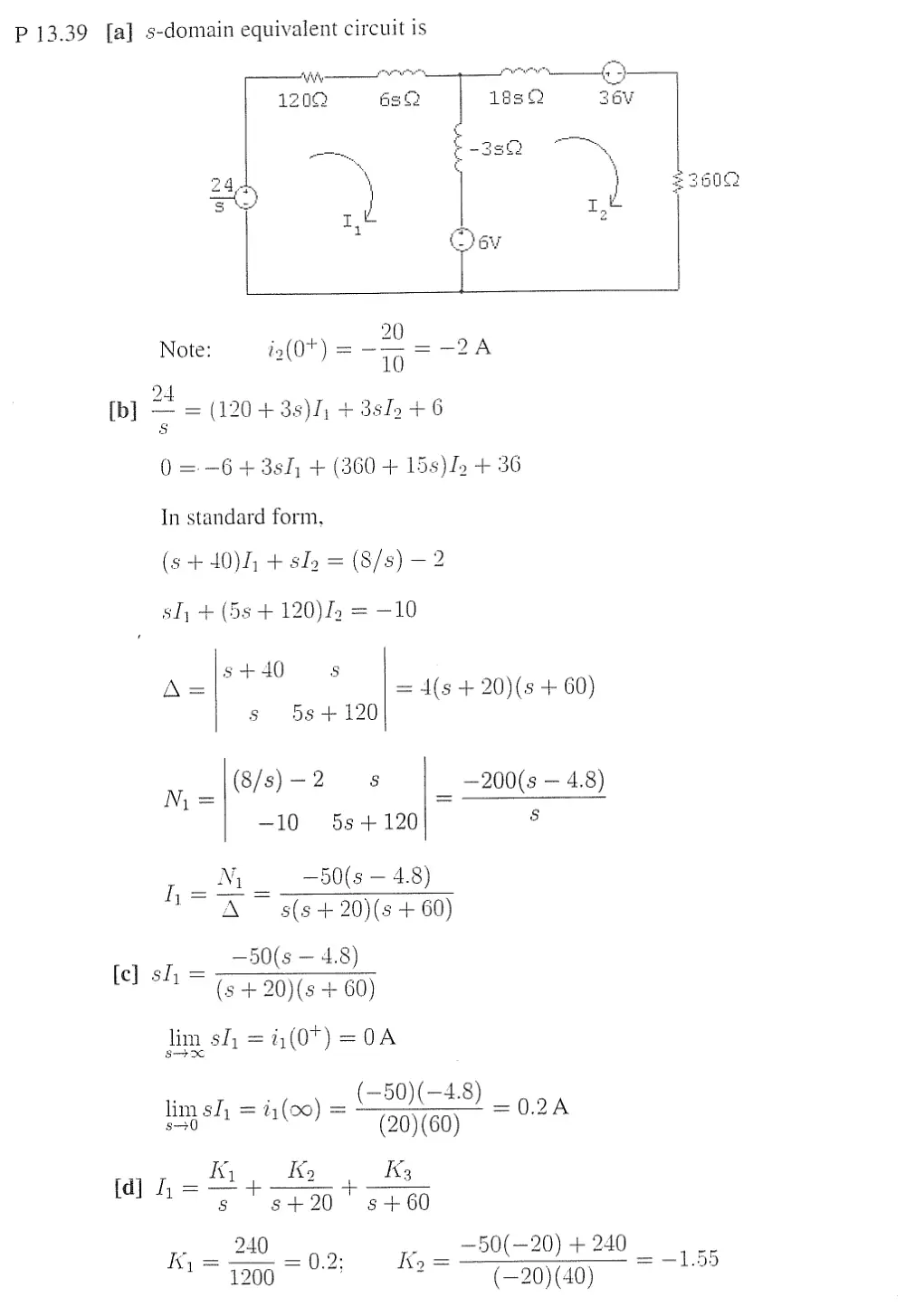
P 13.39 [a] s-domain equivalent circuit is
ANy owe + an 63)
1209 as 18s 36V
§ Sei ——,
ao ¢ -3sb2 \
244 S600
A } gsa0¢
aan Oe
Ss \ re Tt
Ge OV
20
Note: i,(0t) = -— = -2
ote i2(07) 10
[b] — — = (1204 38), + 3slo +6
0=-64 38h, + (3604 15s)In + 36
In standard form,
(6 +40), + slo = (8/8) — 2
sl, + (5s + 120)I5 = —10
5 +40 Ss
A= = d(s + 20)(s + 60)
s 58+ 120
N= (8/s)-2 8 —200(s — 4.8)
1= =
—10 5s+120 7
I Ny, —50(s — 4.8)
A ~ s(s + 20)(s + 60)
—50(s — 4.8
[e) sl, = 50(s — 4.8)
(s + 20)(s + 60)
Jim sh = i,(07) =0A
(—50)(—4.8)
limsh =i = ~ =0.2A
ing sh = (00) = —T99y@O)
fd] hh _ Ky Ko ; K3
8 s+20 s+60
. 240 —50(—2 Qe
Ky = 0.2 Ky = O20) +240 as
12000" ° (—20)(40)
_ =50(-60) +240
A ep rr l. :
8 = ~(—60)(—40) 3
i(t) = [0.2 — 1.55e77" + 1.356 u(t) A
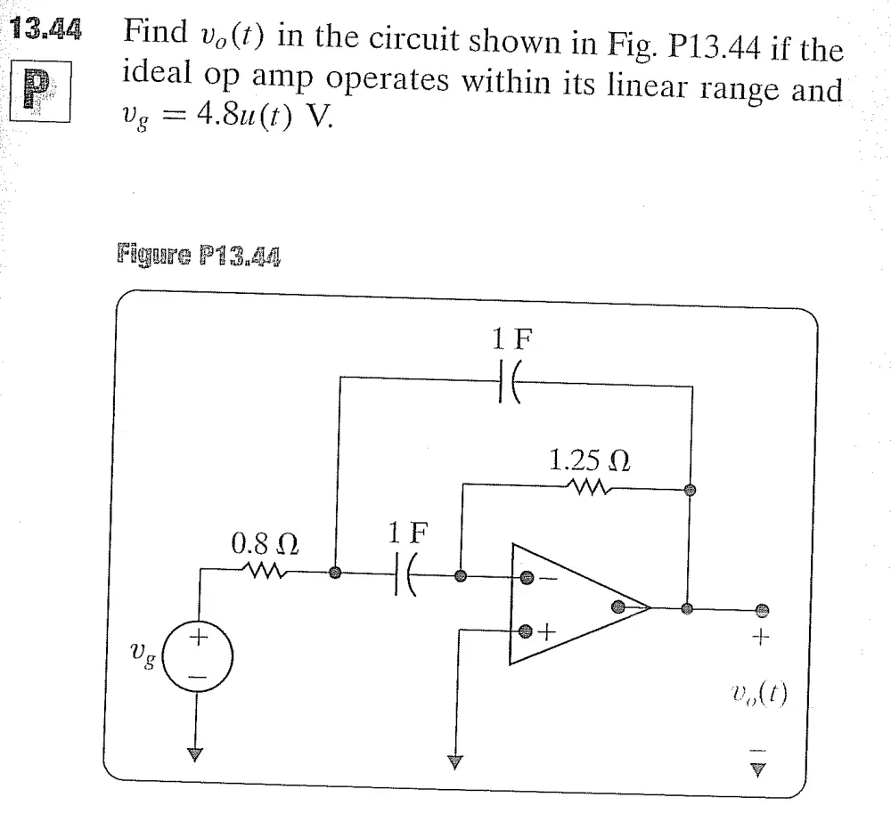
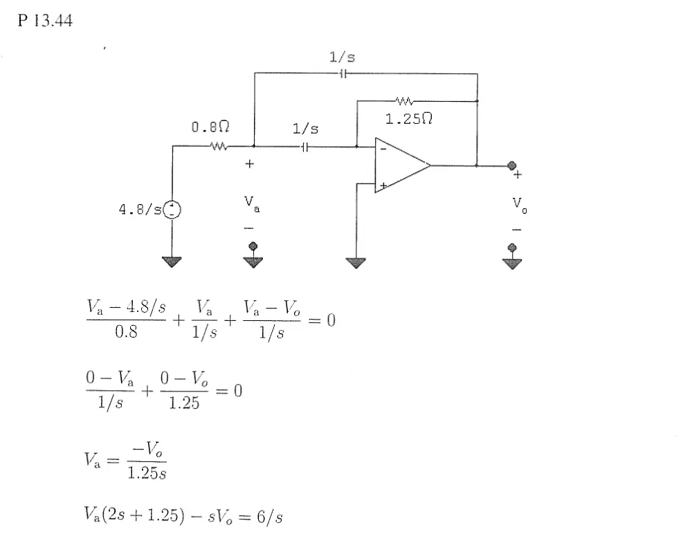
13.44 Find v,(t) in the circuit shown in Fig. P13.44 if the
P ideal op amp operates within its linear range and
i Ve = 4.8u(t) V.
Figure P1344
080 IP
Vv
6 v0)
v v
QO
P 13.44
1.250
V¥, — 4.8/s aM Man Me
08 ‘I/s* I/s |
0-Va O-% _,
1/s 1.25
Y= Vo
1.258
——‘* "i, +
<
o
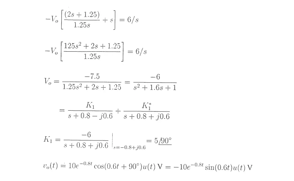
—_ —7.5 —6
° "1.2582 +2641.25 s24+1.6s4+1
_ Ky ; Ay
s+0.8—-j0.6 9 s+0.8+ j0.6
ke —6 | 5 90°
a OO =,
ts +08 + 0.6 |.=-0.8+j0.6
vo(t) = 10e~°*' cos(0.6¢ + 90°)u(t) V = —10e~° sin(0.6¢)u(t) V
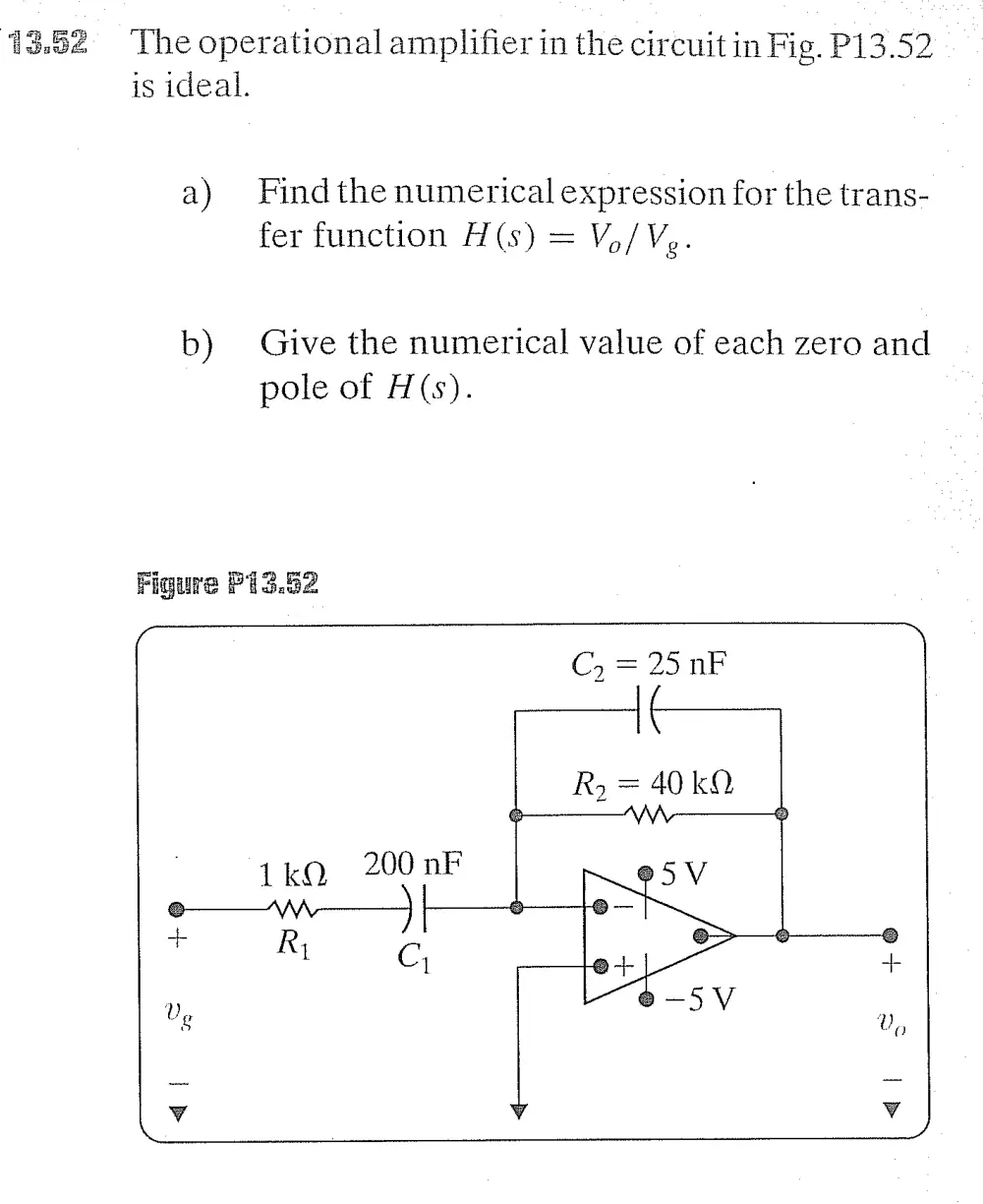
13.62 The operational amplifier in the circuit in Fig. P13.52
is ideal.
a) Findthe numerical expression for the trans-
fer function H(s) = V,/Vg.
b) Give the numerical value of each zero and
pole of H(s).
Figure Pi3.82
1kQ 200 nF
e—w—}
Dg
y y v
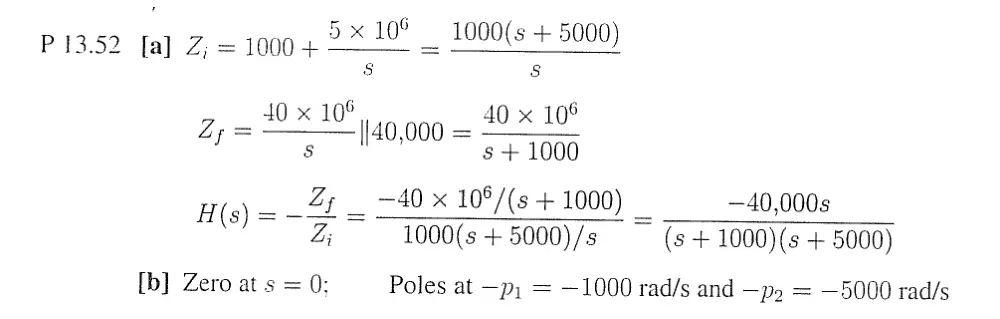
6 1000(s +5
P 13.52 [a] Z,= 1000 4 10 _ 1000(s + 5000)
Ss Ss
40 x 10° 40 x 10°
Z,= 40.000 = 2 1Y
f 5 '40,000 s+ 1000
H(s) = _ 2; — —40 x 108/(s + 1000) —40,000s
Z; 1000(s + 5000)/s (s + 1000)(s + 5000)
[b] Zero at s = 0; Poles at —p; = —1000 rad/s and —p = —5000 rad/s
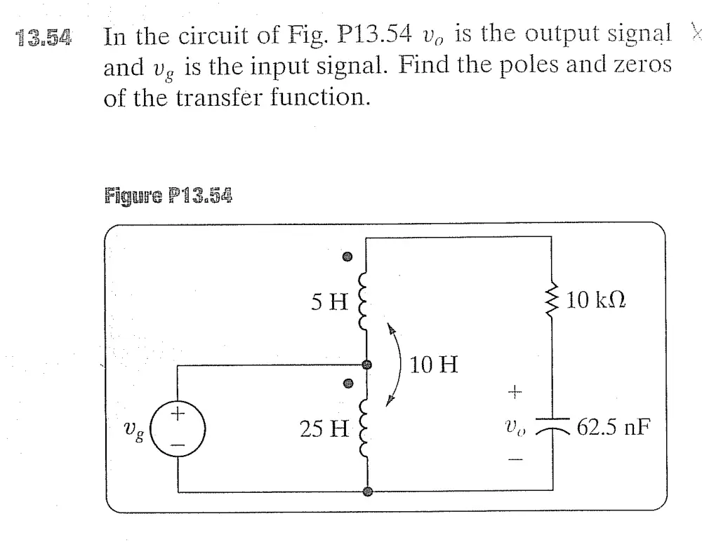
13.54 In the circuit of Fig. P13.54 v, is the output signal *
and vg is the input signal. Find the poles and zeros
of the transfer function.
Figure P13.54
y
e@
SH S 10k
-————» ]10H
° +
+ aL
Ug C) 25H Vo =~ 62.5 nF