
EECE 370 Final, Fall 2012
American University of Beirut · Electric Machines and Power Fundamentals · 3 pages · Prof. Sami Karaki


More EECE 370 files
- Final Solution · Fall 2012Final exam · with solutionView
- Midterm · Summer 2017ExamView
- Lecture Handout 1 · Fall 2016LabView
- Lecture Handout 2 · Fall 2016LabView
- Useful File Formula Sheet · Fall 2014FileView
- Notes Formula Sheet · Summer 2013NotesView
- Homework Intro · Summer 2013HomeworkView
- Problems PROBLEM SET · Fall 2012ProblemsView
Show the text of this final exam
EECE 370 – Final Exam 2008
1
S. KARAKI
AMERICAN UNIVERSITY OF BEIRUT
FALL 2007/ 2008
FACULTY OF ENGINEERING AND ARCHITECTURE
FINAL EXAM
ELECTRIC MACHINES AND POWER SYSTEMS FUNDAMENTALS
(EECE 370)
CLOSED BOOK (2.5 HOURS)
January 30, 2008
PROGRAMMABLE CALCULATORS ARE NOT ALLOWED.
THIS QUESTION SHEET MUST BE RETURNED WITH THE ANSWER BOOKLET.
NAME: _________________________
ID#: _________________________
1. A 20 kVA, 11000/380 V, 3-phase, Y-Y connected distribution transformer has an
impedance referred to the primary of 100 + j500Ω. The components of excitation
branch referred to the primary side are Rc = 490 kΩ and Xm = 100 kΩ. The
transformer is supplying a load having an impedance of 8 + j4 Ω.
a) Given a VA base SB= 10000 VA and a base voltage on the primary side VB1 =
11000 V, determine the secondary base voltage, the base currents and base
impedances on both sides of the transformer. Determine the transformer and load
impedances in per unit. Draw the per unit equivalent circuit and label it with
symbols and values.
b) If the primary voltage is 1.04 per unit, what is the transformer input current and
the active and reactive power supplied at the transformer primary in per unit and
in real quantities? What is the secondary voltage of the transformer in per unit and
in volts?
c) Repeat Part b with a capacitor of –j5Ω connected across the load (i.e. in parallel
with the load impedance). Compare these results with those of Part b and explain
the differences observed in the results.
2. A synchronous generator is rated at 500 kVA, 380V, 50 Hz, 0.85 PF lagging, is Y-
connected, and has two poles. Its armature resistance RA and synchronous reactance
XS are 0.04 and 1.2 per unit on machine rating, respectively. Its friction and windage
losses are 6 kW, its core losses are 7 kW, and it has miscellaneous losses equal to 1
kW. Its open-circuit characteristic is shown in Figure 1.
a) If the generator is supplying power at rated conditions, what are the active and
reactive power supplied by the generator, its internal voltage and the required
field current?
b) If the load drops by 25% but keeps the same power factor, what would be the
terminal voltage of the generator with the field current kept at the value obtained
in Part a?
c) If the governor droop (ω versus P) characteristic has a slope of -5%, what would
be the prime-mover torque required in Parts a, and b above?
EECE 370 – Final Exam 2008
2
Figure 1: Open-Circuit characteristic for the generator in Problem 2
3. A 380V, 50Hz, 4-pole, and Y-connected induction motor (IM) has rated output
power of 50 hp (1hp = 0.746kW) and a class B design. It has been tested in the Lab
with the following results:
No load: 380V, 8.6A, 2148W, 50Hz.
Locked rotor: 98.7V, 70A, 5586W, 50Hz
DC test: 36.4V, 70A
a) Calculate the equivalent circuit parameters of this induction motor R1, X1, R2, X2
and Xm and the no-load rotational losses Prot. Draw the IM equivalent circuit and
label it with symbols and values.
b) When the induction motor is delivering full load power, calculate its slip, rated
current, and the active and reactive power taken from the supply.
c) Calculate the starting current and starting torque of the motor.
150
0
450
300
600
900
750
0
0.1
0.2
0.3
0.4
0.5
0.6
Open-circuit voltage, V
Field current, A
EECE 370 – Final Exam 2008
3
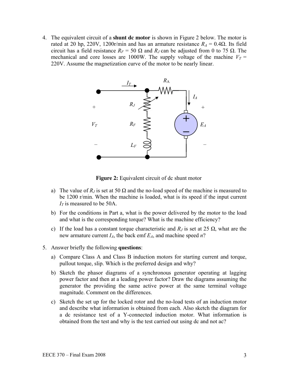
4. The equivalent circuit of a shunt dc motor is shown in Figure 2 below. The motor is
rated at 20 hp, 220V, 1200r/min and has an armature resistance RA = 0.4Ω. Its field
circuit has a field resistance RF = 50 Ω and RJ can be adjusted from 0 to 75 Ω. The
mechanical and core losses are 1000W. The supply voltage of the machine VT =
220V. Assume the magnetization curve of the motor to be nearly linear.
Figure 2: Equivalent circuit of dc shunt motor
a) The value of RJ is set at 50 Ω and the no-load speed of the machine is measured to
be 1200 r/min. When the machine is loaded, what is its speed if the input current
IT is measured to be 50A.
b) For the conditions in Part a, what is the power delivered by the motor to the load
and what is the corresponding torque? What is the machine efficiency?
c) If the load has a constant torque characteristic and RJ is set at 25 Ω, what are the
new armature current IA, the back emf EA, and machine speed n?
5. Answer briefly the following questions:
a) Compare Class A and Class B induction motors for starting current and torque,
pullout torque, slip. Which is the preferred design and why?
b) Sketch the phasor diagrams of a synchronous generator operating at lagging
power factor and then at a leading power factor? Draw the diagrams assuming the
generator the providing the same active power at the same terminal voltage
magnitude. Comment on the differences.
c) Sketch the set up for the locked rotor and the no-load tests of an induction motor
and describe what information is obtained from each. Also sketch the diagram for
a dc resistance test of a Y-connected induction motor. What information is
obtained from the test and why is the test carried out using dc and not ac?
EA
+
–
VT
+
–
RA
RJ
RF
LF
IT
IA