
MECH 220 Final, Fall 2010
American University of Beirut · Engineering Graphics · 6 pages



More MECH 220 files
Show the text of this final exam
AMERICAN UNIVERSITY OF BEIRUT
FACULTY OF ENGINEERING & ARCHITECTURE
Inst. Charbel Seif
FALL 2005-2006
MECH320: Introduction to Engineering CAD
Final Exam
CLOSED BOOK / OPEN MIND
60 Minutes
January 24, 2006
Please sign and date this front sheet PRIOR to working on this test.
I, the undersigned, and in the process of taking this test, pledge that I
(1) will conduct myself in a professional manner
(2) will not communicate with other examinees regarding the subject-matter of
this test while this test is in progress and will ONLY communicate with the
teacher administering this test.
(3) will use only what is handed to me with the exception of a calculator & pens
(4) acknowledge that I am familiar with FEA’s “Rules and Regulations on
Disciplinary Action” and understand that in case of policy violation, that I,
myself, will be responsible for the consequences of my actions.
STUDENT NAME ____________________________
STUDENT ID ____________________________
STUDENT SIGNATURE ____________________________
DATE
____________________________
1
ALL QUESTIONS ARE GRADED EQUALLY; ONE (1) POINT EACH.
VERSION A
1. What is the version of your question sheet?
a- A b- B
DRAWING FORMAT:
2.
Which of the following international regulatory bodies does NOT specify standard drawing formats?
a-
ANSI
b-
DIN
c-
JIS
d-
ISO
e- None of the above
3.
Which of the following does NOT describe a drawing or its intended use?
a-
a drawing is a formatted document
b-
a drawing specifies the required attributes of a part to be manufactured
c-
a drawing is a collection of data that reflects the design intent of the designer
d-
a drawing should stand on its own as far as completeness is concerned
e-
none of the above
4.
Which of the following is NOT a geometric attribute?
a-
Dimension
b-
Flatness
c-
Squareness
d-
Tolerance
e-
None of the above
5.
The following callout
“Obey tolerance block for dimensional tolerances unless otherwise specified.
“
was placed on the drawing in the miscellaneous notes callout. This is the proper location for this callout.
a (TRUE)
b (FALSE)
6.
Where on a drawing format should a callout such as
“Apply Chromate coating Class II prior to painting black (color chip xxx-xx) polyurethane
(Dow Chemical p/n xxxxx)”
be placed?
a-
Main Block
b-
Revision Block
c-
Miscellaneous Notes
d-
None of the above
DIMENSIONING AND TOLERANCING
7.
Which of the following documents govern basic American mechanical drawing formats as well as specifying
proper dimensioning and tolerancing?
a-
ASTM Publication Y15.4
b-
ANSI Publication Y14.5
c-
ISO 9001
d-
ISO 14001
e-
None of the above
2
8.
The following tolerance limits are placed on a nominal dimension so that the tolerancing scheme meets
“Unilateral Dimensioning”:
1.00” +/- 0.001”
a (TRUE)
b (FALSE)
9.
The following dimensions are all equivalent:
16 ½”
16.50”
1’ 4 1/2”
1.650 E+01 in.
a (TRUE)
b (FALSE)
10.
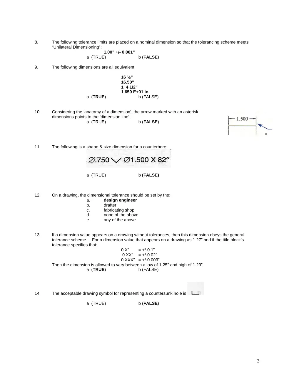
Considering the ‘anatomy of a dimension’, the arrow marked with an asterisk
dimensions points to the ‘dimension line’.
a (TRUE)
b (FALSE)
11.
The following is a shape & size dimension for a counterbore:
a (TRUE)
b (FALSE)
12.
On a drawing, the dimensional tolerance should be set by the:
a.
design engineer
b.
drafter
c.
fabricating shop
d.
none of the above
e.
any of the above
13.
If a dimension value appears on a drawing without tolerances, then this dimension obeys the general
tolerance scheme. For a dimension value that appears on a drawing as 1.27” and if the title block’s
tolerance specifies that:
0.X”
= +/-0.1”
0.XX”
= +/-0.02”
0.XXX”
= +/-0.003”
Then the dimension is allowed to vary between a low of 1.25” and high of 1.29”.
a (TRUE)
b (FALSE)
14.
The acceptable drawing symbol for representing a countersunk hole is
a (TRUE)
b (FALSE)
3
16.
This is a proper method to dimension a circle.
a (TRUE)
b (FALSE)
17.
Given the choice between the two views shown: front view (marked ‘a’)
and the side view (marked ‘b’) which of the two views is the better choice
to place the vertical dimensions?
a.
front view
b.
side view
c.
either view
18.
When using parallel dimensioning each dimension stands alone, not relying on any other dimension for
reference.
a (TRUE)
b (FALSE)
19.
This view shows a proper use of a leader in a
drawing.
a (TRUE)
b (FALSE)
20.
The main disadvantage of ordinate
dimensioning is potential crowding around fine
features.
a (TRUE)
b (FALSE)
VIEWS
21.
The SECTION VIEW shown opposite is an honest representation
of the part when using the straight plane shown on top view.
a (TRUE)
b (FALSE)
4
22.
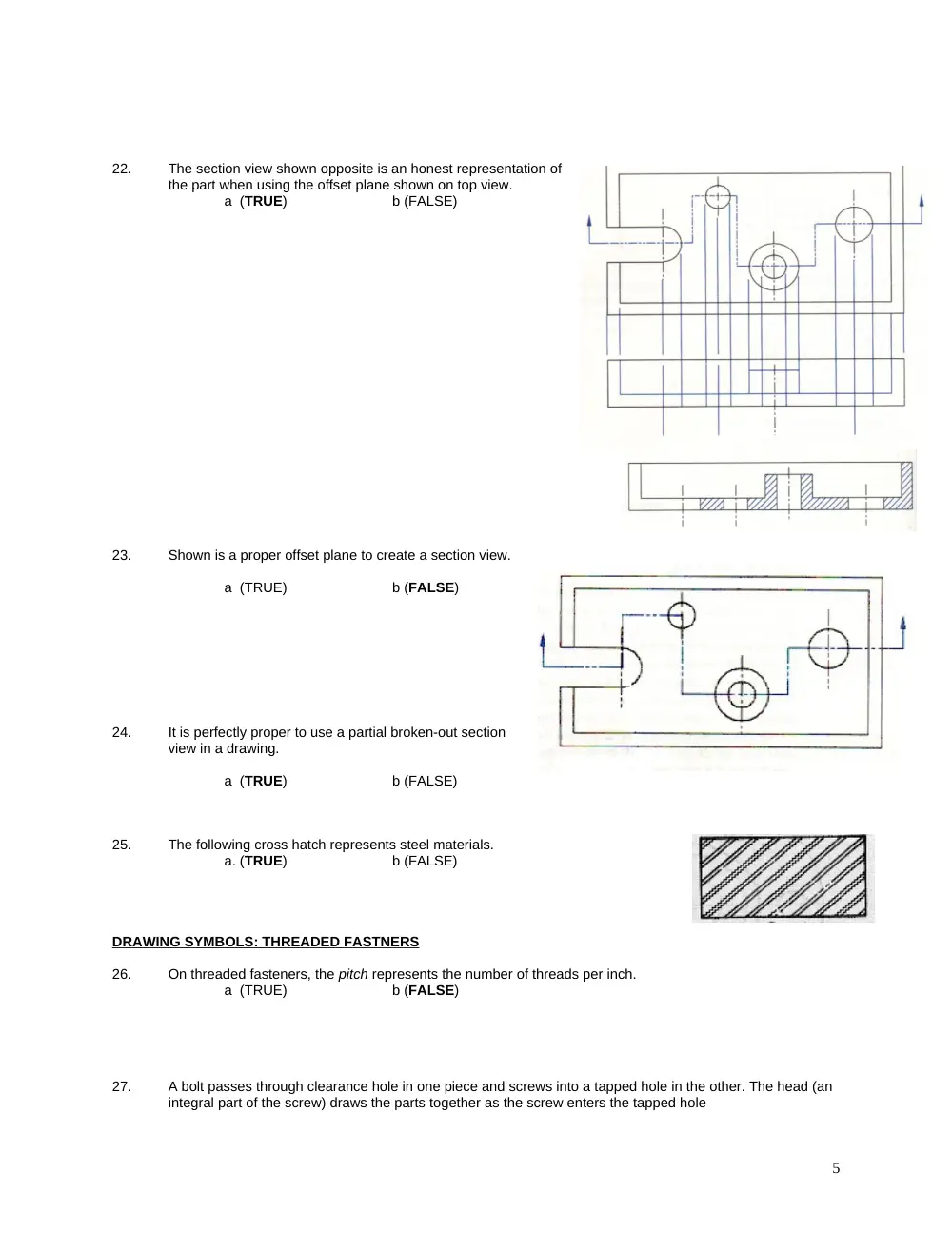
The section view shown opposite is an honest representation of
the part when using the offset plane shown on top view.
a (TRUE)
b (FALSE)
23.
Shown is a proper offset plane to create a section view.
a (TRUE)
b (FALSE)
24.
It is perfectly proper to use a partial broken-out section
view in a drawing.
a (TRUE)
b (FALSE)
25.
The following cross hatch represents steel materials.
a. (TRUE)
b (FALSE)
DRAWING SYMBOLS: THREADED FASTNERS
26.
On threaded fasteners, the pitch represents the number of threads per inch.
a (TRUE)
b (FALSE)
27.
A bolt passes through clearance hole in one piece and screws into a tapped hole in the other. The head (an
integral part of the screw) draws the parts together as the screw enters the tapped hole
5
a (TRUE)
b (FALSE)
28.
This sketch shows a hex head as viewed ‘across the flats’.
a (TRUE)
b (FALSE)
6