
MECH 314 Final, Fall 2006
American University of Beirut · Introduction to Fluids Engineering · 6 pages


More MECH 314 files
- Final 06 · Spring 2014Final examView
- Exam 1 Instructor's Solution · Fall 2018Exam · with solutionView
- Midterm · Fall 2017ExamView
- Exam Qwies · Fall 2017ExamView
- Exam 1 with Solution · Spring 2016Exam · with solutionView
- Drop Quiz 1 · Spring 2014QuizView
- Drop Quiz 1 · Spring 2014QuizView
- Drop Quiz 2 · Spring 2014QuizView
Show the text of this final exam
MECH 411 Introduction to Fluid Mechanics
February 1, 2006
American University of Beirut, Fall 2005-2006
Handout # Final
Final Exam
• This exam is an open book exam.
• All problems have equal weight.
• You have 3 hours.
Problem 1
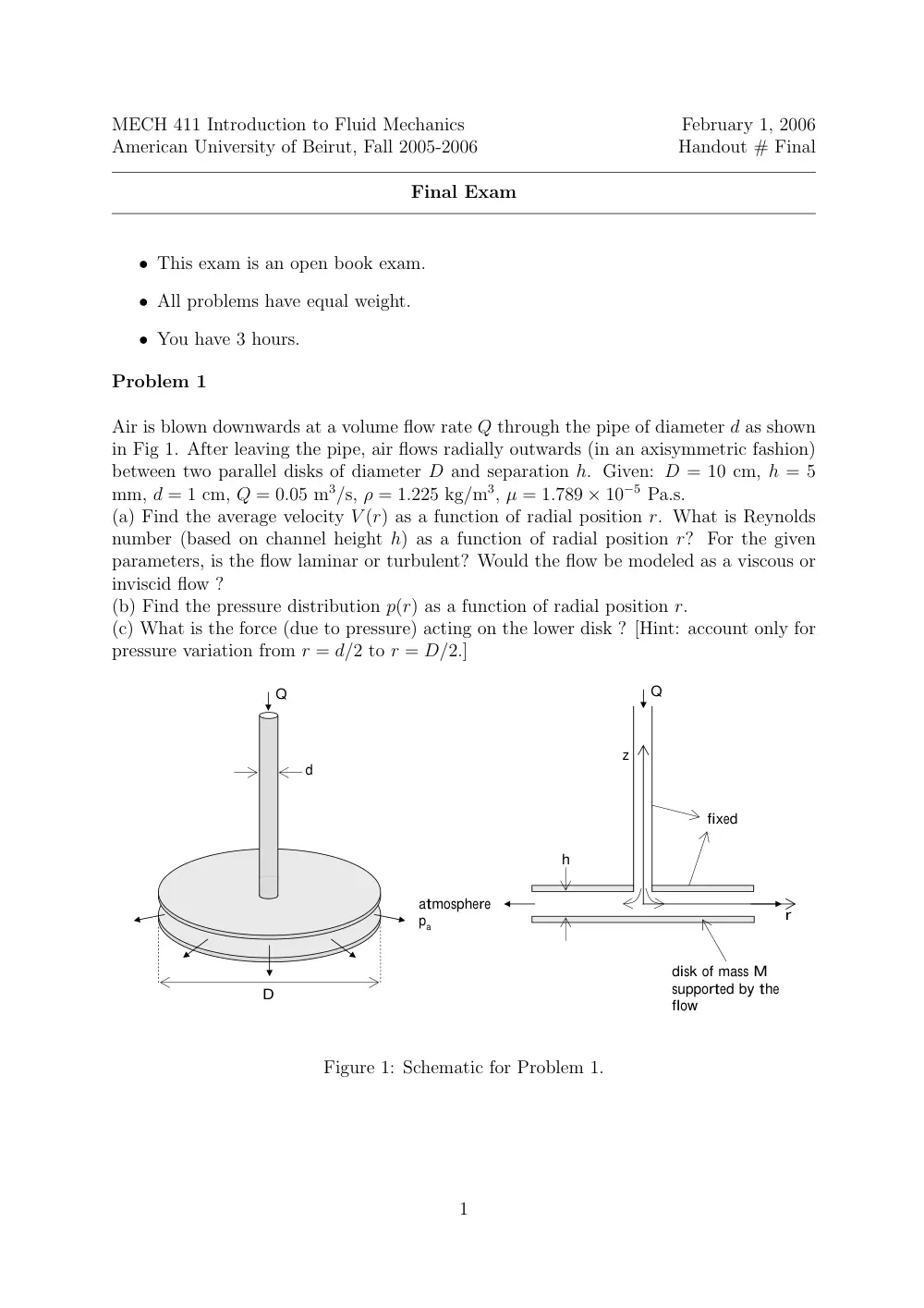
Air is blown downwards at a volume flow rate Q through the pipe of diameter d as shown
in Fig 1. After leaving the pipe, air flows radially outwards (in an axisymmetric fashion)
between two parallel disks of diameter D and separation h. Given: D = 10 cm, h = 5
mm, d = 1 cm, Q = 0.05 m3/s, ρ = 1.225 kg/m3, µ = 1.789 × 10⁻⁵ Pa.s.
(a) Find the average velocity V (r) as a function of radial position r. What is Reynolds
number (based on channel height h) as a function of radial position r? For the given
parameters, is the flow laminar or turbulent? Would the flow be modeled as a viscous or
inviscid flow ?
(b) Find the pressure distribution p(r) as a function of radial position r.
(c) What is the force (due to pressure) acting on the lower disk ? [Hint: account only for
pressure variation from r = d/2 to r = D/2.]
Q
d
D
atmosphere
pa
Q
h
disk of mass M
supported by the
flow
fixed
r
z
Figure 1: Schematic for Problem 1.
1
Problem 2
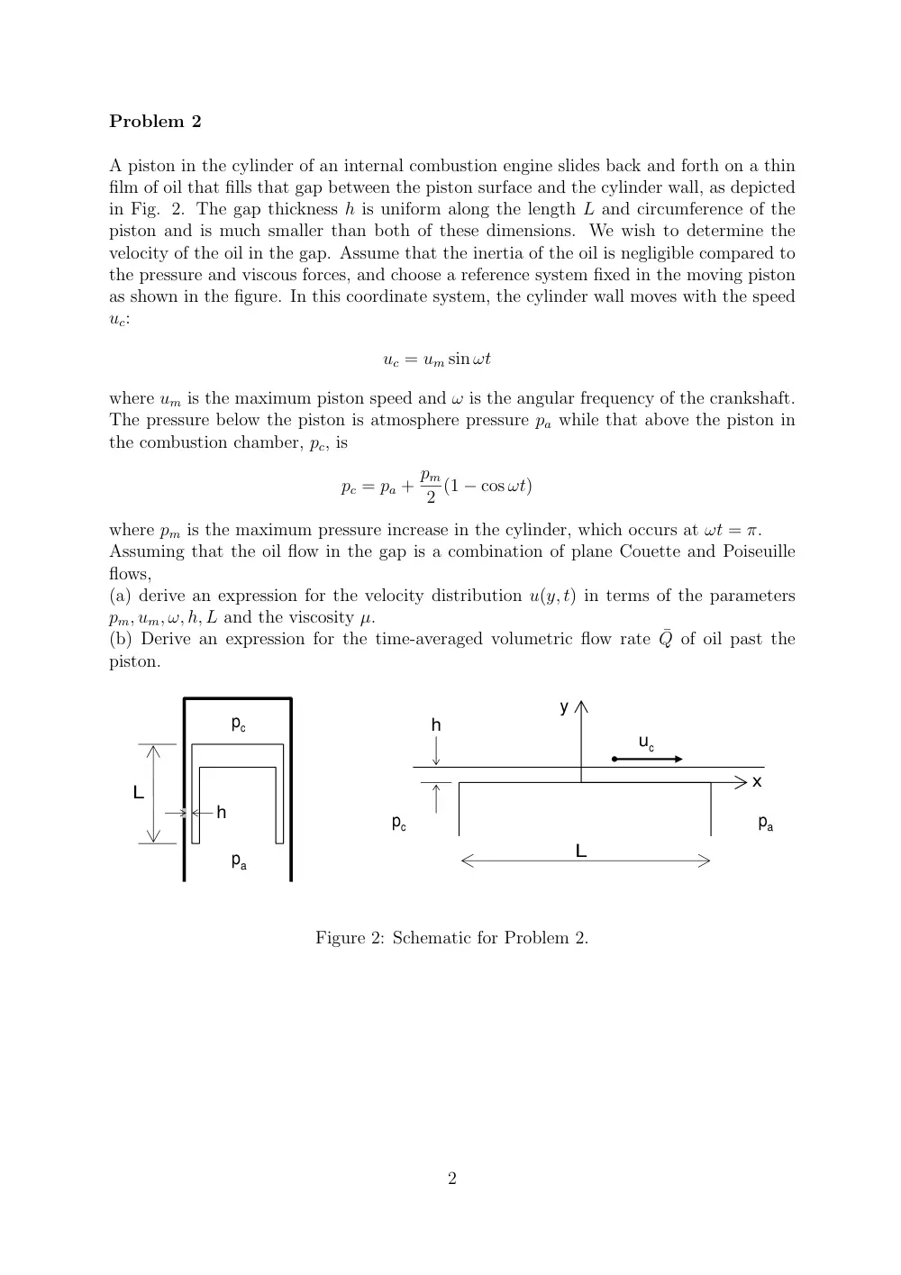
A piston in the cylinder of an internal combustion engine slides back and forth on a thin
film of oil that fills that gap between the piston surface and the cylinder wall, as depicted
in Fig. 2. The gap thickness h is uniform along the length L and circumference of the
piston and is much smaller than both of these dimensions. We wish to determine the
velocity of the oil in the gap. Assume that the inertia of the oil is negligible compared to
the pressure and viscous forces, and choose a reference system fixed in the moving piston
as shown in the figure. In this coordinate system, the cylinder wall moves with the speed
uc:
uc = um sin ωt
where um is the maximum piston speed and ω is the angular frequency of the crankshaft.
The pressure below the piston is atmosphere pressure pa while that above the piston in
the combustion chamber, pc, is
pc = pa + pm
2 (1 − cos ωt)
where pm is the maximum pressure increase in the cylinder, which occurs at ωt = π.
Assuming that the oil flow in the gap is a combination of plane Couette and Poiseuille
flows,
(a) derive an expression for the velocity distribution u(y, t) in terms of the parameters
pm, um, ω, h, L and the viscosity µ.
(b) Derive an expression for the time-averaged volumetric flow rate ¯Q of oil past the
piston.
pc
pa
L
h
pc
pa
h
L
y
x
uc
Figure 2: Schematic for Problem 2.
2
Problem 3
The drag (F) on a submarine moving well below the free surface is to be determined by a
test on a model scaled to 1/20 th of the prototype. The test is to be carried out in a water
tunnel. Determine the ratio of model to prototype drag (Fm/Fp) needed for finding the
prototype drag when the speed of the prototype is 2.57 m/s. The kinematic viscosity of
sea water is 1.3×10⁻⁶ m2/s, and the density is 1010 kg/m3 at the depth of the prototype.
The water in the tunnel has a temperature of 50 ◦C.
If the model submarine were to be tested in a wind tunnel where, at free stream, p = 2000
kPa, and T = 50◦C, what will the ratio Fm/Fp have to be ?
Note: Only the Reynolds number and the Euler number (∆p/ρV 2 ≡ (F/L2)/ρV 2) are im-
portant for dynamic similarity, where L =submarine length. Explain briefly why the Mach
number and the Froude number may be neglected.
3
Problem 4
Water at 10◦C is to flow from reservoir A to reservoir B through a cast-iron pipe of
length 20 m at a rate of Q = 0.0020 m3/s as shown in Fig. 3. The system contains a
sharp-edged entrance and six regular threaded 90 ◦ elbows. Determine the pipe diameter
needed, taking Kelbow = 1.5 [Hint: the friction factor lies between 0.030 and 0.035.]
B
A
total length = L = 20 m
Elevation z2 = 0 m
Elevation z1 = 2 m
D
(2)
(1)
Figure 3: Schematic for Problem 4.
4
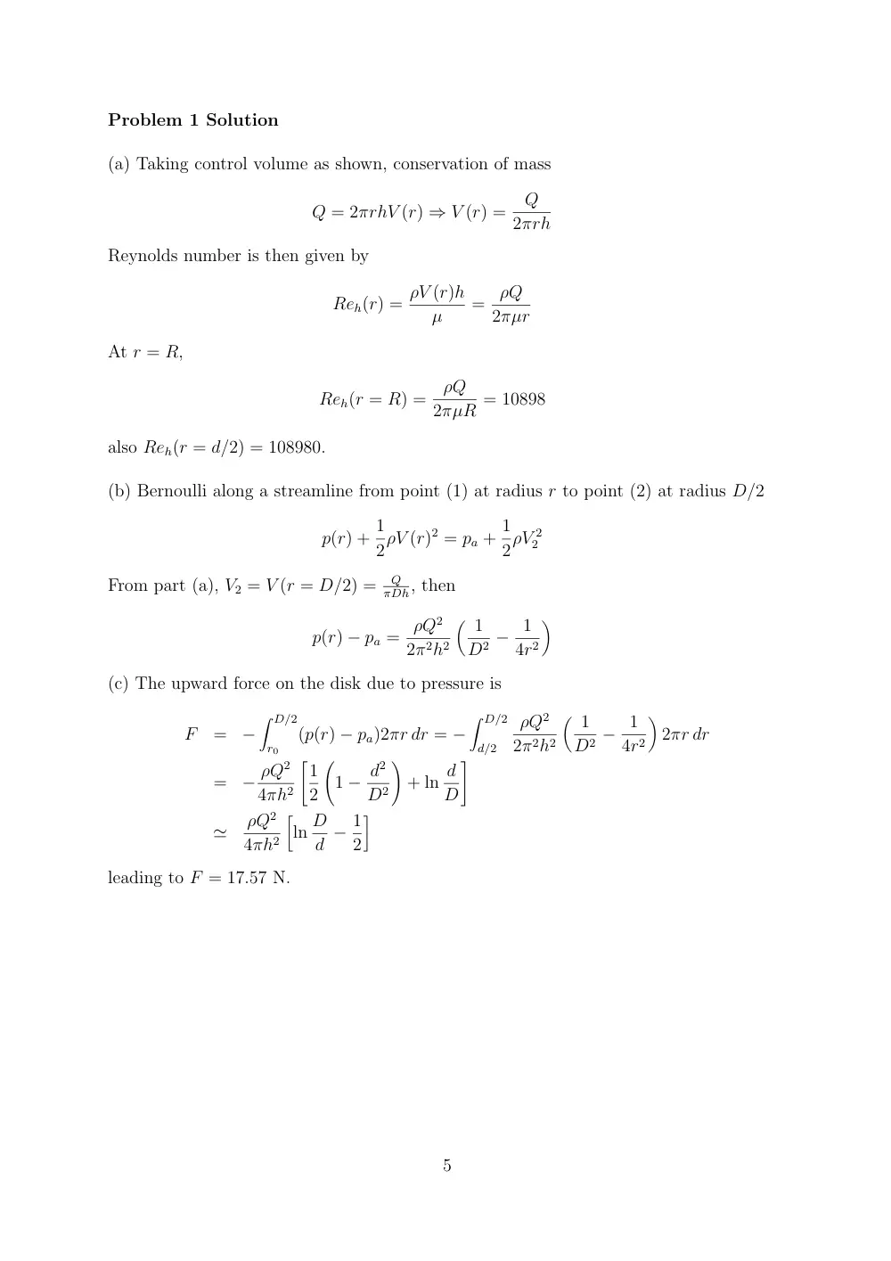
Problem 1 Solution
(a) Taking control volume as shown, conservation of mass
Q = 2πrhV (r) ⇒ V (r) =
Q
2πrh
Reynolds number is then given by
Reh(r) = ρV (r)h
µ
=
ρQ
2πµr
At r = R,
Reh(r = R) =
ρQ
2πµR = 10898
also Reh(r = d/2) = 108980.
(b) Bernoulli along a streamline from point (1) at radius r to point (2) at radius D/2
p(r) + 1
2ρV (r)2 = pa + 1
2ρV 2
2
From part (a), V2 = V (r = D/2) =
Q
πDh, then
p(r) − pa = ρQ2
2π2h2
� 1
D2 − 1
4r2
�
(c) The upward force on the disk due to pressure is
F
=
−
� D/2
r0
(p(r) − pa)2πr dr = −
� D/2
d/2
ρQ2
2π2h2
� 1
D2 − 1
4r2
�
2πr dr
=
− ρQ2
4πh2
�1
2
�
1 − d2
D2
�
+ ln d
D
�
≃
ρQ2
4πh2
�
ln D
d − 1
2
�
leading to F = 17.57 N.
5
Problem 2 Solution
The flow is fully developed with v = 0, so that p = p(x). Momentum in x−direction,
after neglecting the interia term, and ∂2u/∂x2:
dp
dx = µ∂2u
∂y2
⇒
u = 1
2µ
dp
dxy2 + C1y + C2
The boundary conditions are: u = 0 at y = 0 and u = uc at y = h, we
C2 = 0
uc = 1
2µ
dp
dxh2 + C1h ⇒ C1 = − 1
2µ
dp
dxh + uc
h
The velocity field is then given by
u(y, t) = 1
2µ
dp
dx(y2 − hy) + uc
y
h
The volume flow rate is
Q(t) = πDp
� h
0 u(y, t) dy = πDp
�
− h3
12µ
dp
dx + uc
h
2
�
with −dp/dx = pm
2L (1 − cos ωt) and uc = um sin ωt,
Q(t) = πDp
� h3
12µ
pm
2L(1 − cos ωt) + umh
2
sin ωt
�
The time averaged volume flow rate is obtained by averaging over one period
¯Q = ω
2π
� 2π/ω
0
Q(t) dt = πDp
h3
12µ
pm
2L
6