
MECH 340 Problems For Chapter 6, Fall 2011
American University of Beirut · Engineering Materials · 4 pages


More MECH 340 files
- Homework Chapter 6 · Fall 2011ChapterView
- Homework Chapter 1 · Fall 2011ChapterView
- Homework Chapters 2 & 3 · Fall 2011ChapterView
- Exam 1 with Solution · Spring 2013Exam · with solutionView
- Exam 2 with Solution · Spring 2013Exam · with solutionView
- Exam 2 with Solution · Spring 2013Exam · with solutionView
- Exam 1 with Solution · Spring 2012Exam · with solutionView
- Exam 1 · Spring 2011ExamView
Show the text of this chapter
6.17
6.18
6.19
6.20
6.21
6.22
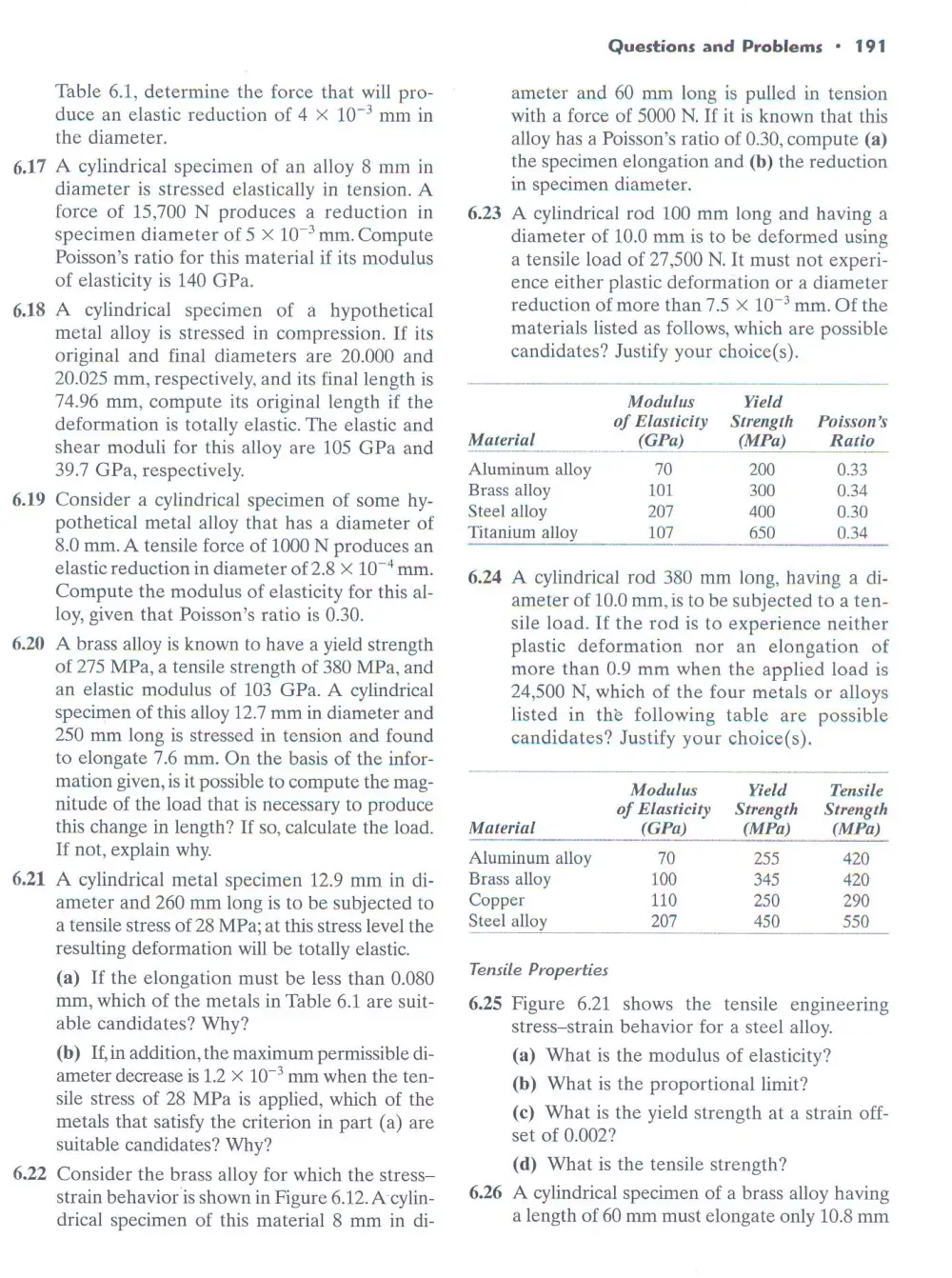
Table 6.1, determine the force that will pro-
duce an elastic reduction of 4 X 10⁷? mm in
the diameter.
A cylindrical specimen of an alloy 8 mm in
diameter is stressed elastically in tension. A
force of 15,700 N produces a reduction in
specimen diameter of 5 X 10°*mm. Compute
Poisson’s ratio for this material if its modulus
of elasticity is 140 GPa.
A cylindrical specimen of a hypothetical
metal alloy is stressed in compression. If its
original and final diameters are 20.000 and
20.025 mm, respectively, and its final length is
74.96 mm, compute its original length if the
deformation is totally elastic. The elastic and
shear moduli for this alloy are 105 GPa and
39.7 GPa, respectively.
Consider a cylindrical specimen of some hy-
pothetical metal alloy that has a diameter of
8.0 mm. A tensile force of 1000 N produces an
elastic reduction in diameter of 2.8 X 10™*mm.
Compute the modulus of elasticity for this al-
loy, given that Poisson’s ratio is 0.30.
A brass alloy is known to have a yield strength
of 275 MPa, a tensile strength of 380 MPa, and
an elastic modulus of 103 GPa. A cylindrical
specimen of this alloy 12.7 mm in diameter and
250 mm long is stressed in tension and found
to elongate 7.6 mm. On the basis of the infor-
mation given, is it possible to compute the mag-
nitude of the load that is necessary to produce
this change in length? If so, calculate the load.
If not, explain why.
A cylindrical metal specimen 12.9 mm in di-
ameter and 260 mm long is to be subjected to
a tensile stress of 28 MPa; at this stress level the
resulting deformation will be totally elastic.
(a) If the elongation must be less than 0.080
mm, which of the metals in Table 6.1 are suit-
able candidates? Why?
(b) If,in addition, the maximum permissible di-
ameter decrease is 1.2 x 10⁻⁷ mm when the ten-
sile stress of 28 MPa is applied, which of the
metals that satisfy the criterion in part (a) are
suitable candidates? Why?
Consider the brass alloy for which the stress—
strain behavior is shown in Figure 6.12. A’cylin-
drical specimen of this material 8 mm in di-
Questions and Problems + 191
ameter and 60 mm long is pulled in tension
with a force of 5000 N. If it is known that this
alloy has a Poisson’s ratio of 0.30, compute (a)
the specimen elongation and (b) the reduction
in specimen diameter.
6.23 A cylindrical rod 100 mm long and having a
diameter of 10.0 mm is to be deformed using
a tensile load of 27,500 N. It must not experi-
ence either plastic deformation or a diameter
reduction of more than 7.5 X 10⁷> mm. Of the
materials listed as follows, which are possible
candidates? Justify your choice(s).
Modulus Yield
of Elasticity Strength Poisson’s
M (GPa) (MPa) __‘ Ratio
Aluminum alloy 70 200 0.33
Brass alloy 101 300 0.34
Steel alloy 207 400 0.30
Titanium alloy 107 650 0.34
6.24 A cylindrical rod 380 mm long, having a di-
ameter of 10.0 mm, is to be subjected to a ten-
sile load. If the rod is to experience neither
plastic deformation nor an elongation of
more than 0.9 mm when the applied load is
24,500 N, which of the four metals or alloys
listed in the following table are possible
candidates? Justify your choice(s).
Yield
Modulus
Tensile
of Elasticity Strength Strength
Material (GPa) (MPa) _(MPa)
Aluminum alloy 70 255 420
Brass alloy 100 345 420
Copper 110 250 290
Steel alloy 207 450 550
Tensile Properties
6.25 Figure 6.21 shows the tensile engineering
stress-strain behavior for a steel alloy.
(a) What is the modulus of elasticity?
(b) What is the proportional limit?
(c) What is the yield strength at a strain off-
set of 0.002?
(d) What is the tensile strength?
6.26 A cylindrical specimen of a brass alloy having
a length of 60 mm must elongate only 10.8 mm
192 - Chapter 6 / Mechanical Properties of Metals
6.27
6.28
6.29
when a tensile load of 50,000 N is applied. Un-
der these circumstances, what must be the ra-
dius of the specimen? Consider this brass al-
loy to have the stress-strain behavior shown in
Figure 6.12.
A load of 85,000 N is applied to a cylindrical
specimen of a steel alloy (displaying the
stress-strain behavior shown in Figure 6.21)
that has a cross-sectional diameter of 20 mm.
(a) Will the specimen experience elastic
and/or plastic deformation? Why?
(b) If the original specimen length is 260 mm,
how much will it increase in length when this
load is applied?
A bar of a steel alloy that exhibits the
stress-strain behavior shown in Figure 6.21 is
subjected to a tensile load; the specimen is 310
mm long and has a square cross section 4.8
mm on a side.
(a) Compute the magnitude of the load nec-
essary to produce an elongation of 0.48 mm.
(b) What will be the deformation after the
load has been released?
A cylindrical specimen of aluminum having a
diameter of 12.8 mm and a gauge length of
50.800 mm is pulled in tension. Use the
load-elongation characteristics shown in
the following table to complete parts (a)
through (f).
Load _ Length
_N _ mm
0 50.800
7,330 50.851
15,100 50.902
23,100 50.952
30,400 51.003
34,400 51.054
38,400 51.308
41,300 51.816
44,800 52.832
46,200 53.848
47,300 54.864
47,500 55.880
46,100 56.896
44,800 57.658
42,600 58.420
36,400 59.182
Fracture
6.30
6.31
(a) Plot the data as engineering stress versus
engineering strain.
(b) Compute the modulus of elasticity.
(c) Determine the yield strength at a strain
offset of 0.002.
(d) Determine the tensile strength of this alloy.
(e) What is the approximate ductility, in per-
cent elongation?
(f) Compute the modulus of resilience.
A specimen of ductile cast iron having a rec-
tangular cross section of dimensions 4.8 mm x
15.9 mm is deformed in tension. Using the
load—-elongation data shown in the following
table, complete parts (a) through (f).
Load Length
N mm
0 75.000
4,740 75.025
9,140 75.050
12,920 75.075
16,540 75.113
18,300 75.150
20,170 75.225
22,900 75:375
25,070 75.525
26,800 15:150
28,640 76.500
30,240 78.000
31,100 79.500
31,280 81.000
30,820 82.500
29,180 84.000
27,190 85.500
24,140 87.000
18,970 88.725
Fracture
(a) Plot the data as engineering stress versus
engineering strain.
(b) Compute the modulus of elasticity.
(c) Determine the yield strength at a strain
offset of 0.002.
(d) Determine the tensile strength of this alloy.
(e) Compute the modulus of resilience.
(f) What is the ductility, in percent elongation?
For the titanium alloy, whose stress-strain be-
havior may be observed in the “Tensile Tests”
Metal Alloys
6.32
Metal Alloys
6.33
a
letal Alloys
6.34
etal Alloys
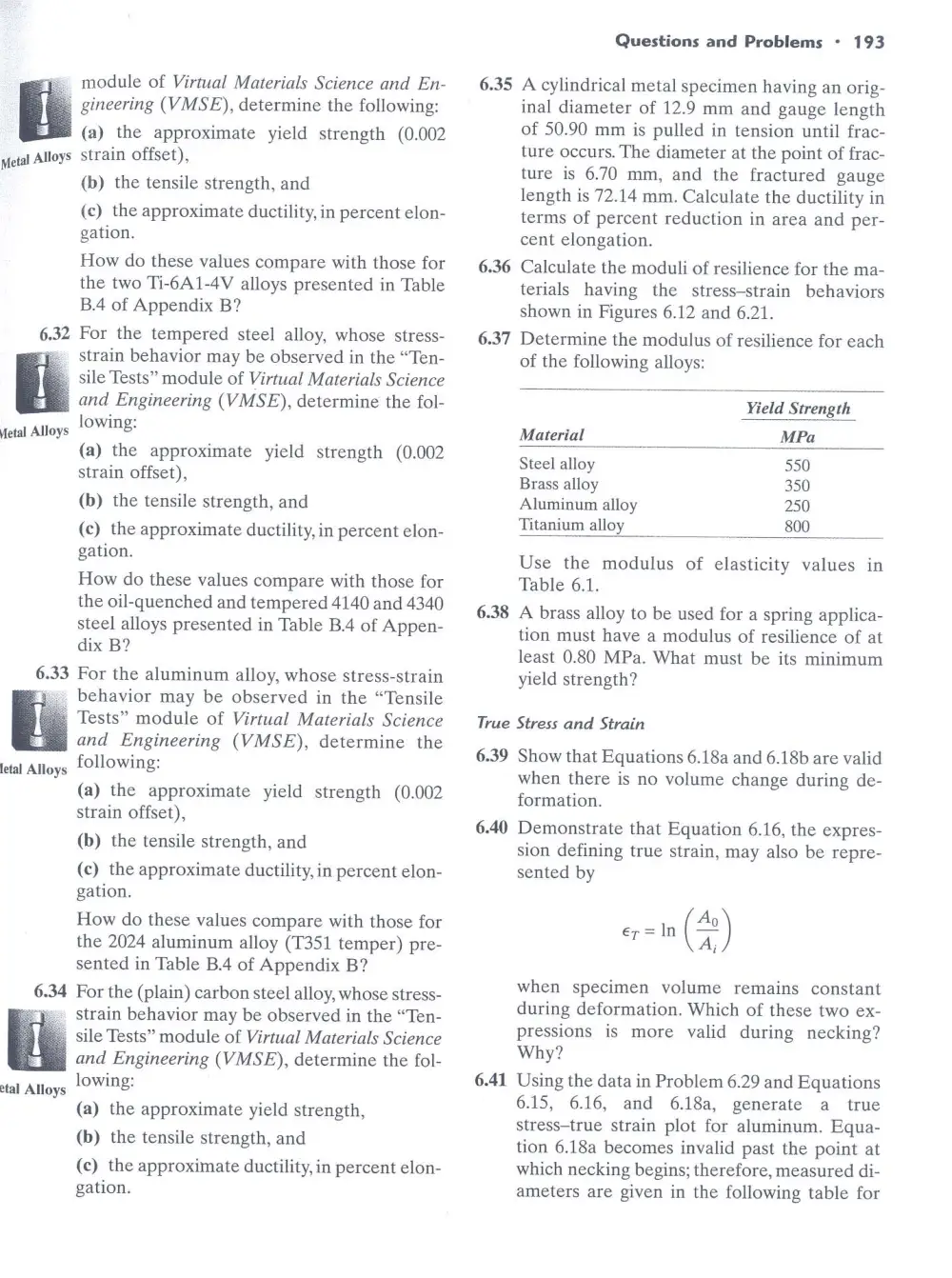
module of Virtual Materials Science and En-
gineering (VMSE), determine the following:
(a) the approximate yield strength (0.002
strain offset),
(b) the tensile strength, and
(c) the approximate ductility, in percent elon-
gation.
How do these values compare with those for
the two Ti-6A1-4V alloys presented in Table
B.4 of Appendix B?
For the tempered steel alloy, whose stress-
strain behavior may be observed in the “Ten-
sile Tests” module of Virtual Materials Science
and Engineering (VMSE), determine the fol-
lowing:
(a) the approximate yield strength (0.002
strain offset),
(b) the tensile strength, and
(c) the approximate ductility, in percent elon-
gation.
How do these values compare with those for
the oil-quenched and tempered 4140 and 4340
steel alloys presented in Table B.4 of Appen-
dix B?
For the aluminum alloy, whose stress-strain
behavior may be observed in the “Tensile
Tests” module of Virtual Materials Science
and Engineering (VMSE), determine the
following:
(a) the approximate yield strength (0.002
strain offset),
(b) the tensile strength, and
(c) the approximate ductility, in percent elon-
gation.
How do these values compare with those for
the 2024 aluminum alloy (T351 temper) pre-
sented in Table B.4 of Appendix B?
For the (plain) carbon steel alloy, whose stress-
strain behavior may be observed in the “Ten-
sile Tests” module of Virtual Materials Science
and Engineering (VMSE), determine the fol-
lowing:
(a) the approximate yield strength,
(b) the tensile strength, and
(c) the approximate ductility, in percent elon-
gation.
6.35
6.36
6.37
6.38
True
6.39
6.40
6.41
Questions and Problems - 193
A cylindrical metal specimen having an orig-
inal diameter of 12.9 mm and gauge length
of 50.90 mm is pulled in tension until frac-
ture occurs. The diameter at the point of frac-
ture is 6.70 mm, and the fractured gauge
length is 72.14 mm. Calculate the ductility in
terms of percent reduction in area and per-
cent elongation.
Calculate the moduli of resilience for the ma-
terials having the stress-strain behaviors
shown in Figures 6.12 and 6.21.
Determine the modulus of resilience for each
of the following alloys:
Yield Strength
Material MPa
Steel alloy 550
Brass alloy 350
Aluminum alloy 250
Titanium alloy 800
Use the modulus of elasticity values in
Table 6.1.
A brass alloy to be used for a spring applica-
tion must have a modulus of resilience of at
least 0.80 MPa. What must be its minimum
yield strength?
Stress and Strain
Show that Equations 6.18a and 6.18b are valid
when there is no volume change during de-
formation.
Demonstrate that Equation 6.16, the expres-
sion defining true strain, may also be repre-
sented by
A
€r= In (4)
when specimen volume remains constant
during deformation. Which of these two ex-
pressions is more valid during necking?
Why?
Using the data in Problem 6.29 and Equations
6.15, 6.16, and 6.18a, generate a true
stress-true strain plot for aluminum. Equa-
tion 6.18a becomes invalid past the point at
which necking begins; therefore, measured di-
ameters are given in the following table for
194 -
6.42
6.43
6.44
6.45
6.46
the last four data points, which should be used
in true stress computations.
_ Length _
_ Diameter _
— a ll TM.
56.896 11-71
57.658 10.95
58.420 10.62
59.182 9.40
A tensile test is performed on a metal speci-
men, and it is found that a true plastic strain
of 0.20 is produced when a true stress of 575
MPa is applied; for the same metal, the value
of K in Equation 6.19 is 860 MPa. Calculate
the true strain that results from the applica-
tion of a true stress of 600 MPa.
For some metal alloy, a true stress of 415 MPa
produces a plastic true strain of 0.475. How
much will a specimen of this material elon-
gate when a true stress of 325 MPa is applied
if the original length is 300 mm? Assume a
value of 0.25 for the strain-hardening expo-
nent n.
The following true stresses produce the corre-
sponding true plastic strains for a brass alloy:
True Stress
MPa) __ True Strain
345 0.10
15 020
What true stress is necessary to produce a true
plastic strain of 0.25?
For a brass alloy, the following engineering
stresses produce the corresponding plastic en-
gineering strains, prior to necking:
Engineering Stress
___ (MPa) _ ___ Engineering Strain
235 0.194
250 0.296
On the basis of this information, compute the
engineering stress necessary to produce an en-
gineering strain of 0.25.
Find the toughness (or energy to cause frac-
ture) for a metal that experiences both elas-
tic and plastic deformation. Assume Equation
6.5 for elastic deformation, that the modulus
Chapter 6 / Mechanical Properties of Metals
6.47
6.48
of elasticity is 172 GPa, and that elastic de-
formation terminates at a strain of 0.01. For
plastic deformation, assume that the relation-
ship between stress and strain is described by
Equation 6.19, in which the values for K and
n are 6900 MPa and 0.30, respectively. Fur-
thermore, plastic deformation occurs between
strain values of 0.01 and 0.75, at which point
fracture occurs.
For a tensile test, it can be demonstrated that
necking begins when
ate
or (6.26)
der
Using Equation 6.19, determine the value of
the true strain at this onset of necking.
Taking the logarithm of both sides of Equa-
tion 6.19 yields
logo; = logK + nloger (6.27)
Thus, a plot of log a versus log €7 in the plas-
tic region to the point of necking should yield
a straight line having a slope of and an in-
tercept (at log o = 0) of log K.
Using the appropriate data tabulated in
Problem 6.29, make a plot of log a, versus
log ey and determine the values of n and K.
Tt will be necessary to convert engineering
stresses and strains to true stresses and strains
using Equations 6.18a and 6.18b.
Elastic Recovery after Plastic Deformation
6.49
6.50
A cylindrical specimen of a brass alloy 7.8 mm
in diameter and 95.0 mm long is pulled in ten-
sion with a force of 6000 N; the force is subse-
quently released.
(a) Compute the final length of the specimen
at this time. The tensile stress-strain behavior
for this alloy is shown in Figure 6.12.
(b) Compute the final specimen length when
the load is increased to 16,500 N and then re-
leased.
A steel alloy specimen having a rectangular
cross section of dimensions 12.7 mm x 6.4
mm has the stress-strain behavior shown in
Figure 6.21. If this specimen is subjected to a
tensile force of 38,000 N, then
(a) Determine the elastic and plastic strain
values.