
PHYS 228 Final, Fall 2005
American University of Beirut · Electronics · 6 pages
More PHYS 228 files
Show the text of this final exam
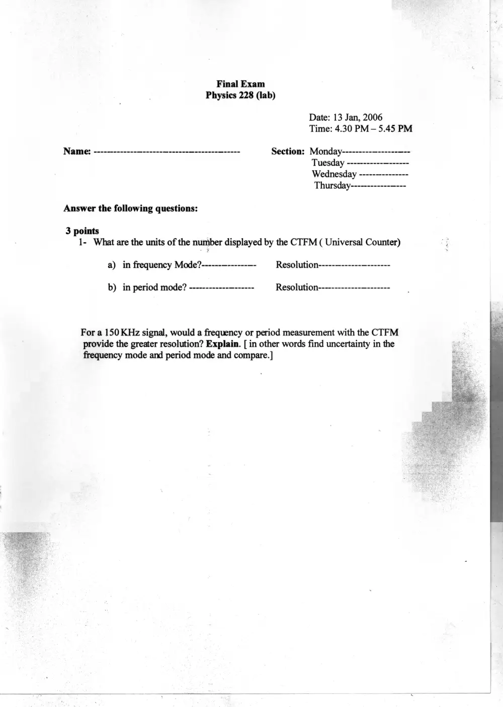
Final Exam
Physics 228 (lab)
Date: 13 Jan, 2006
Time: 4.30 PM—5.45 PM
Name: -------------—------—------—-------—----- Section: Monday---------—------—--
Tuesday ----------- 7
Wednesday ----- -
Answer the following questions:
3 points
1- What are the units of the number displayed by the CTFM ( Universal Counter)
a) in frequency Mode?------—------—- Resolution-------------—-------
b) in period mode? ------------—------ Resolution-------------—-------
For a 150 KHz signal, would a frequency or period measurement with the CTFM
provide the greater resolution? Explain. [ in other words find uncertainty in the
frequency mode and period mode and compare.]
3 points
2- a) Can you obtain a 1.99 MHz square wave signal from your ( Furction
Generator)?
b) Can you obtain a 5 Volts sine wave signal from your ( Function Generator)
using TTL output?
c) Can you obtain a triangular wave signal having a peak value of 20 volts from
your ( Function Generator)?
2 points
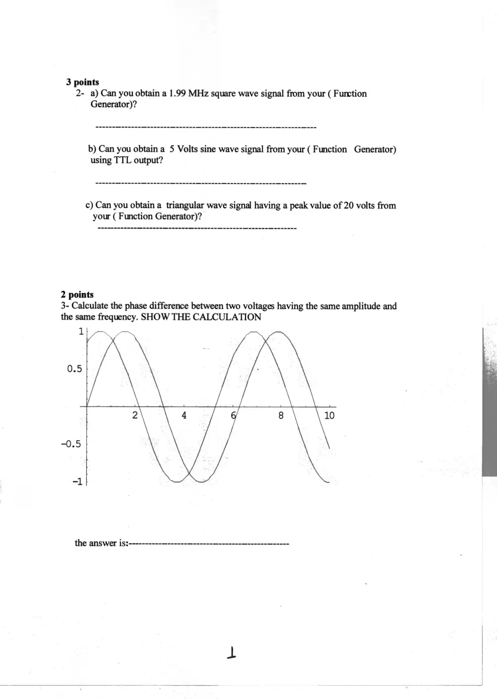
3- Calculate the phase difference between two voltages having the same amplitude and
the same frequency. SHOW THE CALCULATION
1
0.5
the answer is:----------—------—------—-------—------—-----
a
2- points
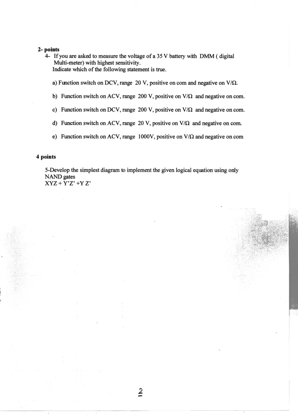
4- Ifyou are asked to measure the voltage of a 35 V battery with DMM ( digital
Multi-meter) with highest sensitivity.
Indicate which of the following statement is true.
a) Function switch on DCV, range 20 V, positive on com and negative on V/Q.
b) Function switch on ACV, range 200 V, positive on V/Q and negative on com.
c) Function switch on DCV, range 200 V, positive on V/Q and negative on com.
d) Function switch on ACV, range 20 V, positive on V/Q and negative on com.
e) Function switch on ACV, range 1000V, positive on V/Q and negative on com
4 points
5-Develop the simplest diagram to implement the given logical equation using only
NAND gates
XYZ + Y°Z’ +Y Z’
5 points
6- Indicate whether the following statements are true or false:
a) The screen of the oscilloscope can provide a voltage against time display--
b) The screen of the oscilloscope can provide a voltage against another
c) Any phenomenon that can be converted into a voltage can be measured
with an oscilloscope-------
d) The screen of the oscilloscope can provide a lissajous figure if the two
channels are connected to the voltage sources and the scope display is
switched to X-Y mode ------
e) Output of a “NOR gate is “ONE” if all inputs are (ZERO) -----
5 points
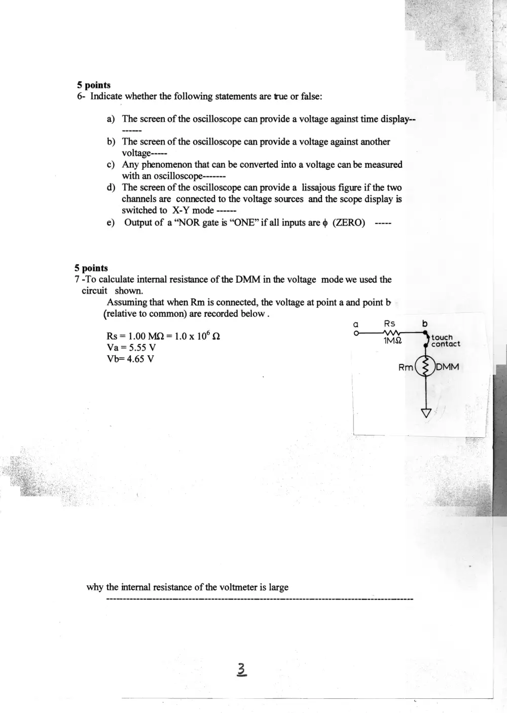
7 -To calculate internal resistance of the DMM in the voltage mode we used the
circuit shown.
Assuming that when Rm is connected, the voltage at point a and point b
(relative to common) are recorded below .
a RS b
Rs = 1.00 MQ = 1.0.x 10°Q IMO touch
Va=5.55 V contact
Vb= 4.65 V
Rm( 3 )DMM
why the internal resistance of the voltmeter is large
5 points
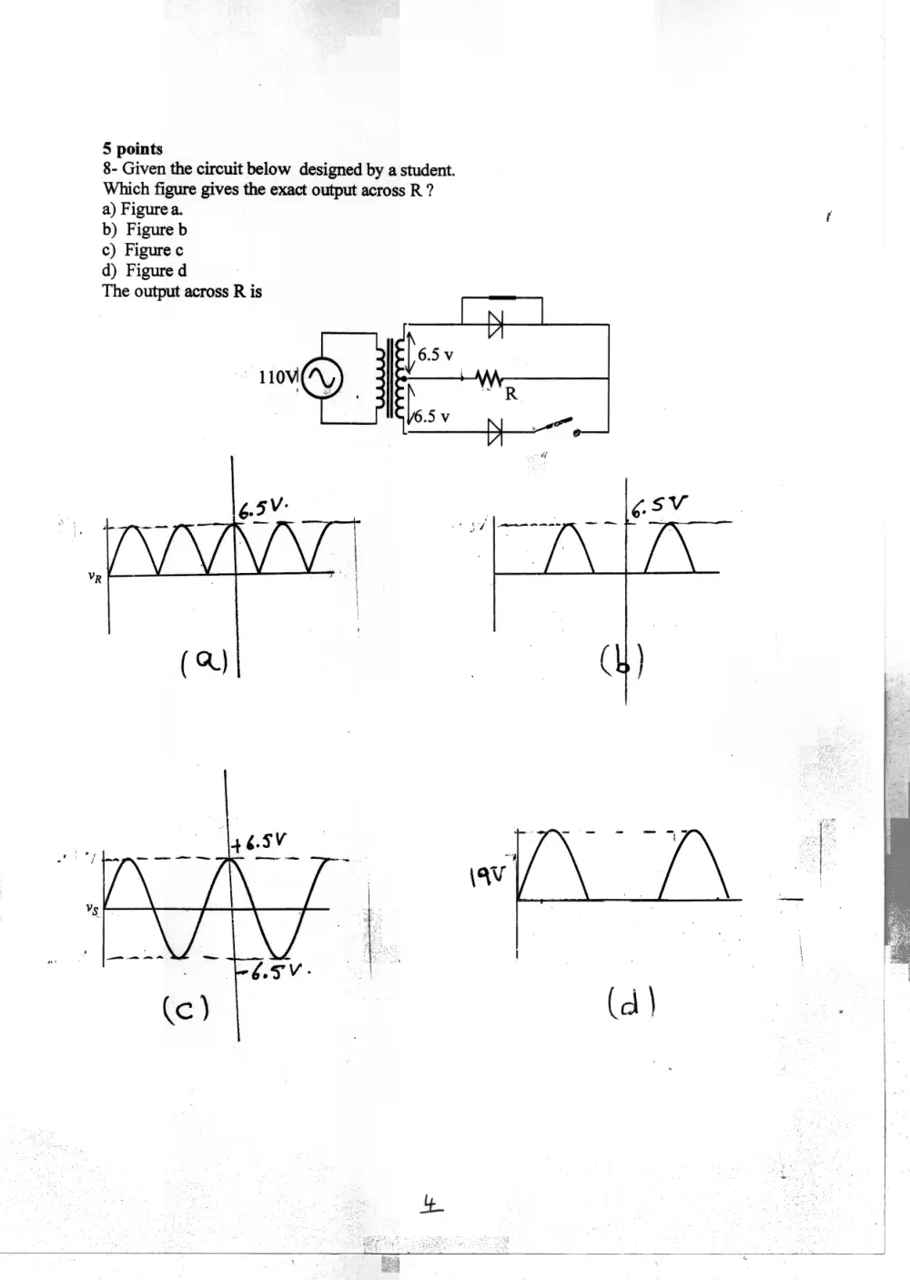
8- Given the circuit below designed by a student.
Which figure gives the exact output across R ?
a) Figure a. f
b) Figure b
c) Figure c
d) Figure d
The output across R is
110V
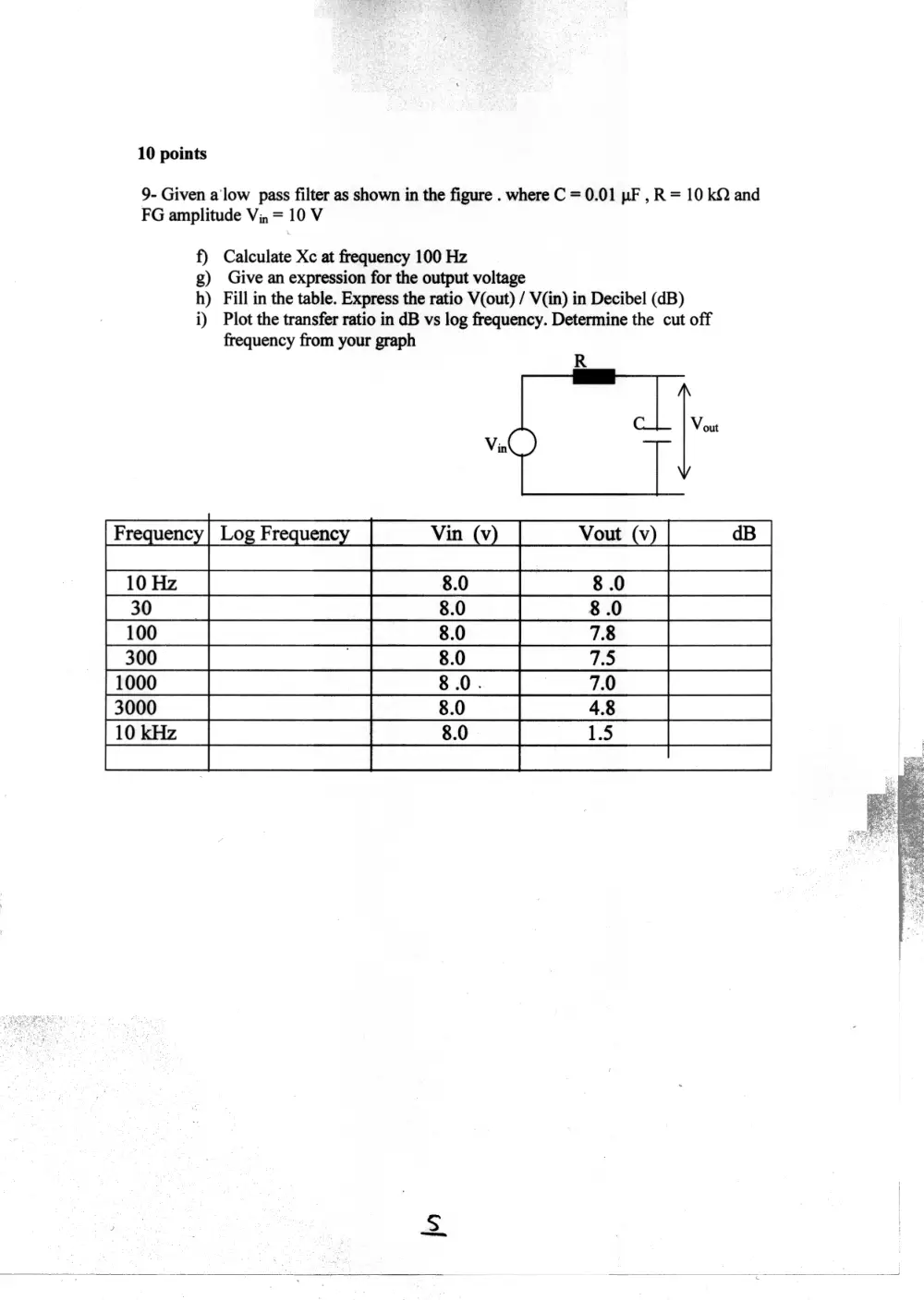
10 points
9- Given a'low pass filter as shown in the figure . where C = 0.01 pF , R = 10 kQ and
FG amplitude Vi, = 10 V
f) Calculate Xc at frequency 100 Hz
g) Give an expression for the output voltage
h) Fill in the table. Express the ratio V(out) / V(in) in Decibel (dB)
i) Plot the transfer ratio in dB vs log frequency. Determine the cut off
frequency from your graph
Frequency| Log Frequency
[10 Hz
30
100
300
[1000
3000
10 kHz