
CCE 220 Project Final Project Spring 2012, Spring 2012
American University of Science and Technology · Digital Systems · 3 pages

Show the text of this final exam
Name: Ahmad Bazzi ( 12100563)
Digital Systems Lab Project: Logic Probe
Spring 2012 Semester
Logic Probe circuit used:
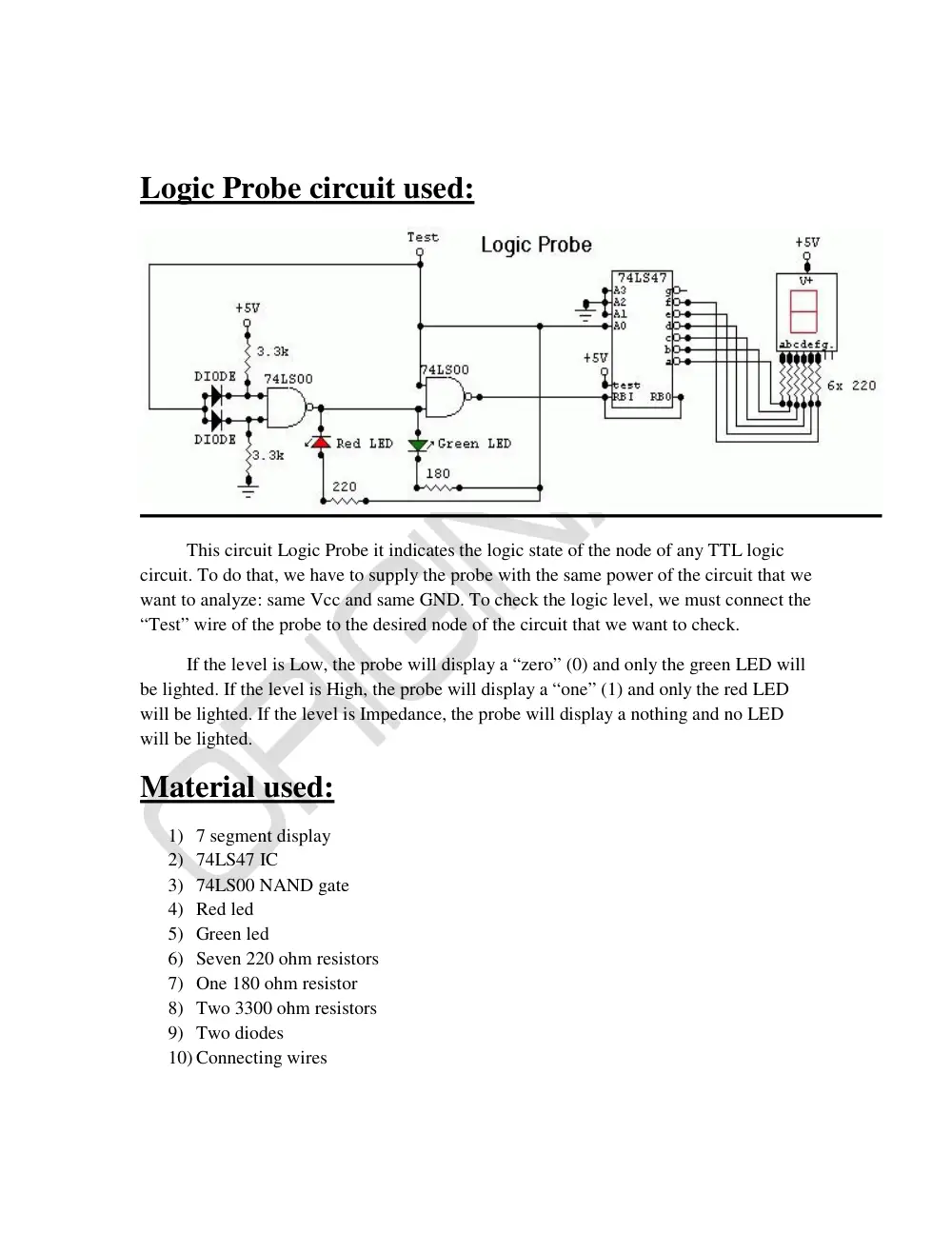
This circuit Logic Probe it indicates the logic state of the node of any TTL logic
circuit. To do that, we have to supply the probe with the same power of the circuit that we
want to analyze: same Vcc and same GND. To check the logic level, we must connect the
“Test” wire of the probe to the desired node of the circuit that we want to check.
If the level is Low, the probe will display a “zero” (0) and only the green LED will
be lighted. If the level is High, the probe will display a “one” (1) and only the red LED
will be lighted. If the level is Impedance, the probe will display a nothing and no LED
will be lighted.
Material used:
1) 7 segment display
2) 74LS47 IC
3) 74LS00 NAND gate
4) Red led
5) Green led
6) Seven 220 ohm resistors
7) One 180 ohm resistor
8) Two 3300 ohm resistors
9) Two diodes
10) Connecting wires
Logic Probe PCB Making :
Procedure and problems faced:
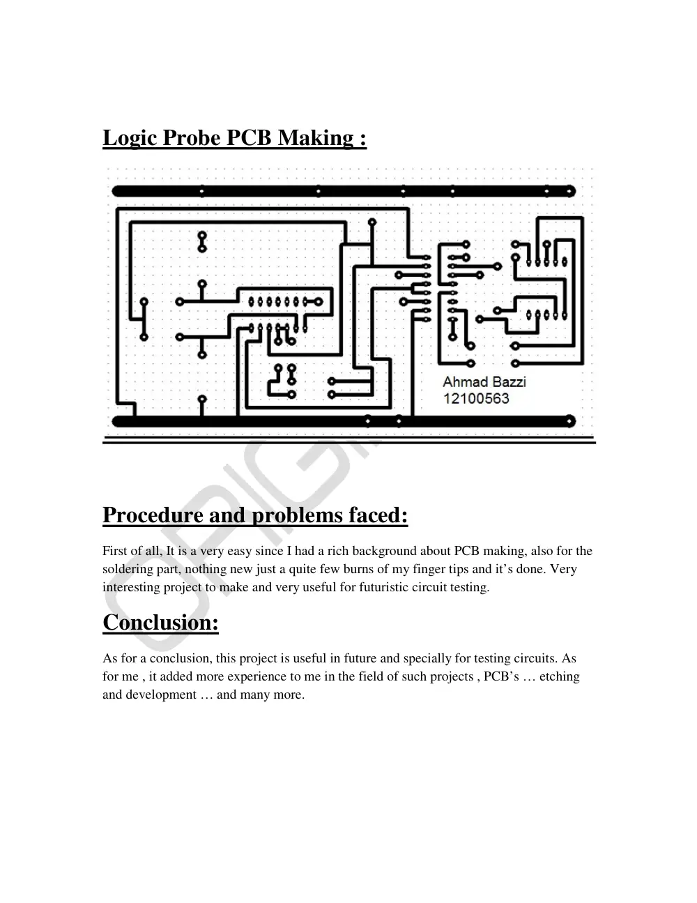
First of all, It is a very easy since I had a rich background about PCB making, also for the
soldering part, nothing new just a quite few burns of my finger tips and it’s done. Very
interesting project to make and very useful for futuristic circuit testing.
Conclusion:
As for a conclusion, this project is useful in future and specially for testing circuits. As
for me , it added more experience to me in the field of such projects , PCB’s … etching
and development … and many more.