
COE 799 Lecture 2, Fall 2011
Lebanese American University · Optical Networks · 95 pages · Dr. Wissam Fawaz

Showing the first 10 of 95 pages. Download the PDF to see all of it.
More COE 799 files
Show the text of this lab
Connection-Oriented Networks – Wissam FAWAZ
1
Chapter 2:
SONET/SDH and GFP
TOPICS
– T1/E1
– SONET/SDH - STS 1, STS -3 frames
– SONET devices
– Self-healing rings
– Generic frame protocol, and Data over SONET
Connection-Oriented Networks – Wissam FAWAZ
2
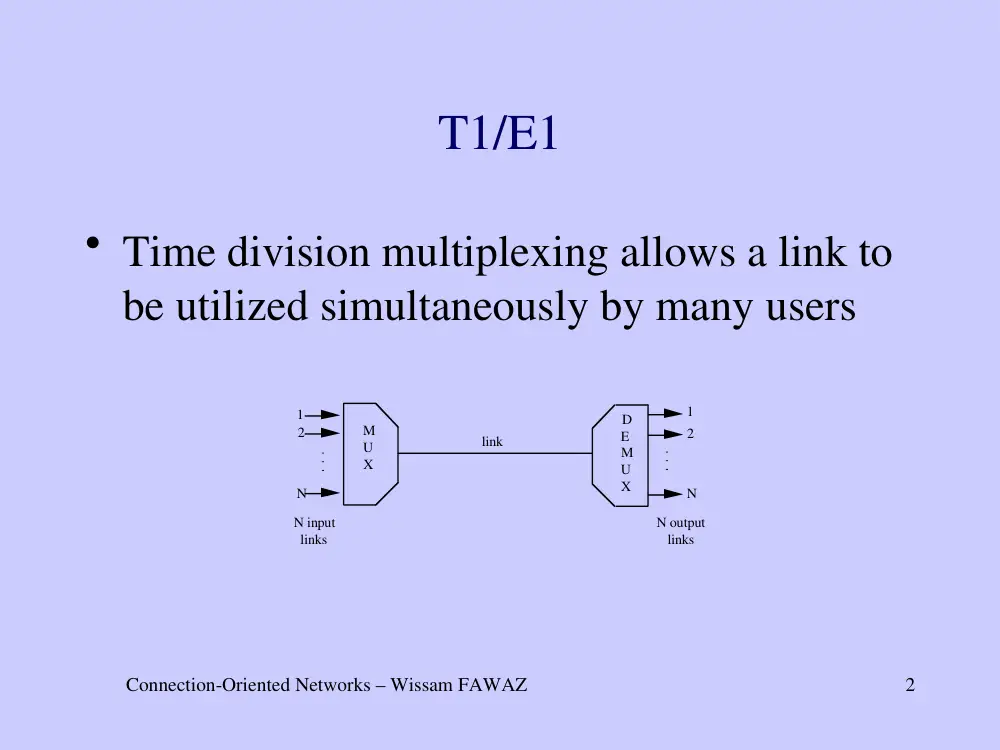
T1/E1
• Time division multiplexing allows a link to
be utilized simultaneously by many users
M
U
X
D
E
M
U
X
N input
links
N output
links
link
1
2
N
1
2
N
Connection-Oriented Networks – Wissam FAWAZ
3
• The transmission is organized into frames.
• Each frame contains a fixed number of time slots.
• Each time slot is pre-assigned to a specific input
link. The duration of a time slot is either a bit or a
byte.
• If the buffer of an input link has no data, then its
associated time slot is transmitted empty.
• A time slot dedicated to an input link repeats
continuously frame after frame, thus forming a
channel or a trunk.
Connection-Oriented Networks – Wissam FAWAZ
4
Pulse code modulation
• TDM is used in telephony
• Voice analog signals are digitized at the end
office using Pulse Code Modulation.
• A voice signal is sampled 8000 times/sec,
or every 125 sec.
• A 7-bit or 8-bit number is created every 125
sec.
Connection-Oriented Networks – Wissam FAWAZ
5
The Digital Signal (DS) and
ITU-T standard
• A North American standard that specifies how to
multiplex several voice calls onto a single link.
• The DS standard is a North American standard and
it is not the same as the international hierarchy
standardized by ITU-T.
• Both standards are independent of the transmission.
Connection-Oriented Networks – Wissam FAWAZ
6
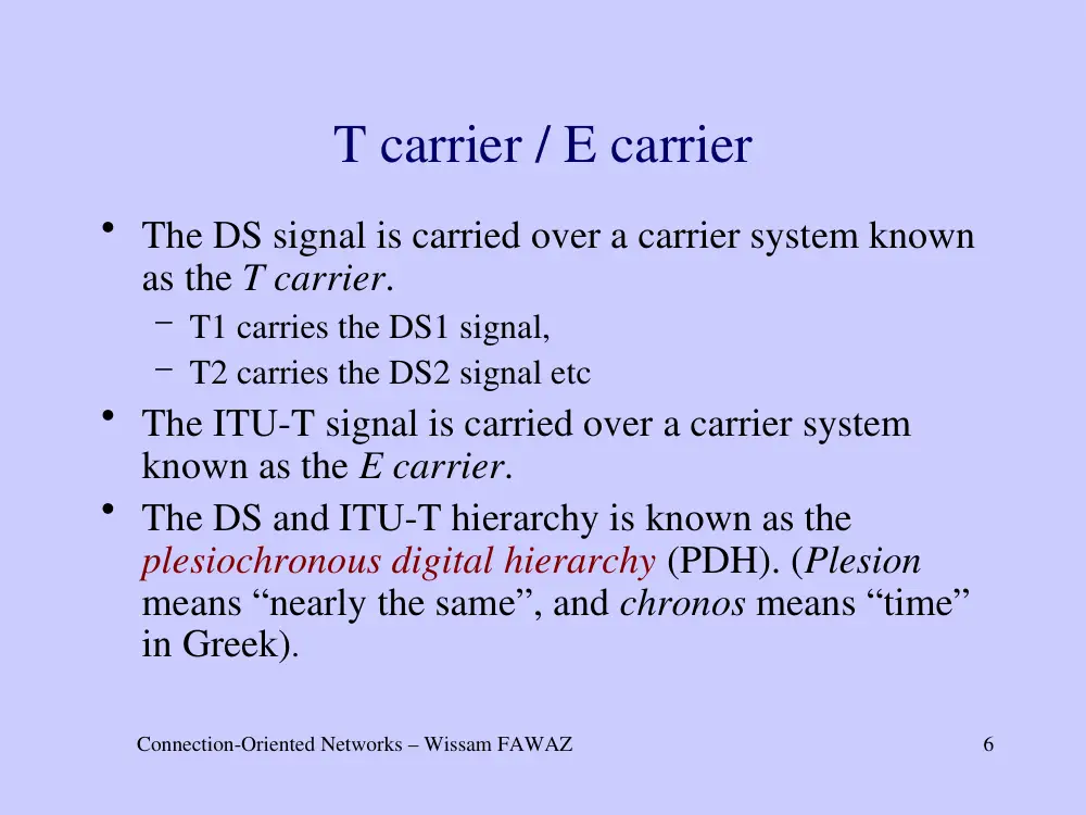
T carrier / E carrier
• The DS signal is carried over a carrier system known
as the T carrier.
– T1 carries the DS1 signal,
– T2 carries the DS2 signal etc
• The ITU-T signal is carried over a carrier system
known as the E carrier.
• The DS and ITU-T hierarchy is known as the
plesiochronous digital hierarchy (PDH). (Plesion
means “nearly the same”, and chronos means “time”
in Greek).
Connection-Oriented Networks – Wissam FAWAZ
7
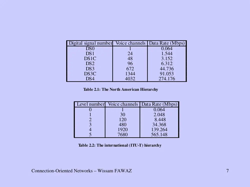
Digital signal number Voice channels Data Rate (Mbps)
DS0
1
0.064
DS1
24
1.544
DS1C
48
3.152
DS2
96
6.312
DS3
672
44.736
DS3C
1344
91.053
DS4
4032
274.176
Table 2.1: The North American Hierarchy
Level number Voice channels Data Rate (Mbps)
0
1
0.064
1
30
2.048
2
120
8.448
3
480
34.368
4
1920
139.264
5
7680
565.148
Table 2.2: The international (ITU-T) hierarchy
Connection-Oriented Networks – Wissam FAWAZ
8
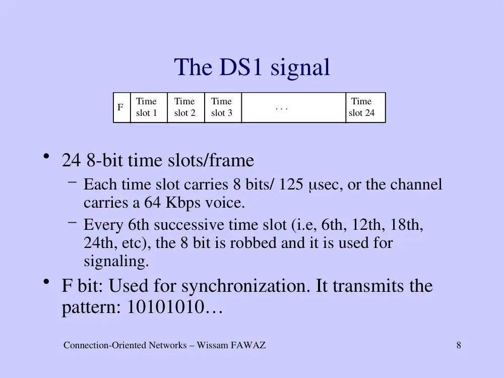
The DS1 signal
• 24 8-bit time slots/frame
– Each time slot carries 8 bits/ 125 sec, or the channel
carries a 64 Kbps voice.
– Every 6th successive time slot (i.e, 6th, 12th, 18th,
24th, etc), the 8 bit is robbed and it is used for
signaling.
• F bit: Used for synchronization. It transmits the
pattern: 10101010…
F
Time
slot 1
Time
slot 2
Time
slot 3
Time
slot 24
. . .
Connection-Oriented Networks – Wissam FAWAZ
9
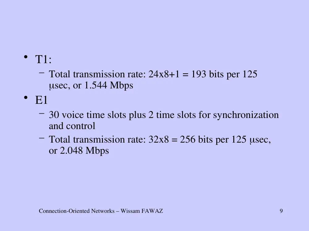
• T1:
– Total transmission rate: 24x8+1 = 193 bits per 125
sec, or 1.544 Mbps
• E1
– 30 voice time slots plus 2 time slots for synchronization
and control
– Total transmission rate: 32x8 = 256 bits per 125 sec,
or 2.048 Mbps
Connection-Oriented Networks – Wissam FAWAZ
10
Fractional T1/E1
• Fractional T1 or E1 allows the use of only a
fraction of the T1 or E1 capacity.
• For example: if N=2, then only two time
slots are used per frame, which corresponds
to a channel with total bandwidth of 128
Kbps.
Connection-Oriented Networks – Wissam FAWAZ
11
Unchannelized frame signal
• The time slot boundaries are ignored by the
sending and receiving equipment.
• All 192 bits are used to transport data followed by
the 193rd framing bit.
• This approach permits more flexibility in
transmitting at different rates.
• This scheme is implemented using proprietary
solutions.
Connection-Oriented Networks – Wissam FAWAZ
12
The Synchronous Optical NETwork
(SONET)
• Proposed by Bellcore (Telecordia).
– It was designed to multiplex DS-n signals and
transmit them optically.
• ITU-T adopted the Synchronous Digital
Hierarchy (SDH), as the international
standard.
– It enables the multiplexing of level 3 signals
(34.368 Mbps)
Connection-Oriented Networks – Wissam FAWAZ
13
STS, STM, OC
• The electrical side of the SONET signal is
known as the synchronous transport signal
(STS)
• The electrical side of the SDH is known as
the synchronous transport module (STM).
• The optical side of a SONET/SDH signal is
known as the optical carrier (OC).
Connection-Oriented Networks – Wissam FAWAZ
14
The SONET/SDH hierarchy
Optical
level
SONET
level
(electrical)
SDH
level
(electrical)
Data rate
(Mbps)
Overhead
rate
(Mbps)
Payload
rate
(Mbps)
OC-1
STS-1
-
51.840
1.728
50.112
OC-3
STS-3
STM-1
155.520
5.184
150.336
OC-9
STS-9
STM-3
466.560
15.552
451.008
OC-12
STS-12
STM-4
622.080
20.736
601.344
OC-18
STS-18
STM-6
933.120
31.104
902.016
OC-24
STS-24
STM-8
1244.160
41.472
1202.688
Oc-36
STS-36
STM-12
1866.240
62.208
1804.932
OC-48
STS-48
STM-16
2488.320
82.944
2405.376
OC-96
STS-96
STM-32
4976.640
165.888
4810.752
OC-192
STS-192
STM-64
9953.280
331.776
9621.504
OC-768
STS-768
STM-256
39813.120
1327.104
38486.016
OC-N
STS-N
STM-N/3
N*51.840
N*1.728
N*50.112
Connection-Oriented Networks – Wissam FAWAZ
15
• SONET/SDH is channelized.
– STS-3 consists of 3 STS-1 streams, and each STS-
1 consists of a number of DS-1 and E1 signals.
– STS-12 consists of 12 STS-1 streams
• Concatenated structures (OC-3c, OC-12c, etc)
– The frame of the STS-3 payload is filled with
ATM cells or IP packets packed in PPP or HDLC
frames.
– Concatenated SONET/SDH links are commonly
used to interconnect ATM switches and IP routers
(Packets over SONET).
Connection-Oriented Networks – Wissam FAWAZ
16
The STS-1 frame structure
1
2
3
4
5
6
…
90
1
1
2
3
4
5
6
…
90
2
91
92
93
94
95
96
…
180
3
181
182
183
184
185
186
…
270
4
271
272
273
274
275
276
…
360
5
361
362
363
364
365
366
…
450
6
451
452
453
454
455
456
…
560
7
561
562
563
564
565
566
…
630
8
631
632
636
634
635
636
…
720
9
721
722
723
724
725
726
…
810
Connection-Oriented Networks – Wissam FAWAZ
17
• Main features
– The frame is presented in matrix form and it is
transmitted row by row.
– Each cell in the matrix corresponds to a byte
– The first three columns contain overheads
– The remaining 87 columns carry the
synchronous payload envelope (SPE), which
consists of user data, and additional overheads
referred to as the payload overhead (POH)
Connection-Oriented Networks – Wissam FAWAZ
18
An SPE may straddle between
two successive frames
Frame i
Frame i+1
1 2 3 4 5 6 . . . 90
1
2
3
4
5
6
7
8
9
276
276
275
. . .
. . .
. . .
. . .
. . .
. . .
. . .
. . .
. . .
. . .
. . .
. . .
. . .
. . .
. . .
. . .
. . .
. . .
1
2
3
4
5
6
7
8
9
Connection-Oriented Networks – Wissam FAWAZ
19
The section, line, and path overheads
Section
Line
STS-1
STS-1
A
B
regenerator
regenerator
STS-1
A1
A12
STS-12
.
.
.
STS-1
B1
B12
STS-12
.
.
.
Section
Section
Section
Section
Line
Line
Path
Connection-Oriented Networks – Wissam FAWAZ
20
• Section: a single link with a SONET device
or a regenerator on either side of it.
• Line: A link between two SONET devices,
which may include regenerators
• The section overhead in the SONET frame
is associated with the transport of STS-1
frames over a section, and the line overhead
is associated with the transport of SPEs over
a line.
Connection-Oriented Networks – Wissam FAWAZ
21
The SONET stack
Section
Line
Path
Photonic
Section
Line
Path
Photonic
Section
Line
Photonic
Section
Photonic
Section
Photonic
Section
Line
Photonic
Ai
A
Regenerator
Regenerator
Bi
B
Connection-Oriented Networks – Wissam FAWAZ
22
STS-1: Section and line overheads
SOH
LOH
Column
1
2
3
1
A1
A2
J0
2
B1
E1
F1
3
D1
D2
D3
4
H1
H2
H3
5
B2
K1
K2
6
D4
D5
D6
7
D7
D8
D9
8
D10
D11
D12
9
Z1
Z2
E2
Connection-Oriented Networks – Wissam FAWAZ
23
• The following are some of the bytes in the
section overhead (SOH) :
– A1 and A2: These two bytes are called the
framing bytes and they are used for frame
alignment. They are populated with the value
1111 0110 0010 1000 or 0xF628, which
uniquely identifies the beginning of an STS-
frame.
– J0: This is called the section trace byte and it
is used for to trace the STS-1 frame back to its
originating equipment.
Connection-Oriented Networks – Wissam FAWAZ
24
– B1: This byte is the bit interleaved parity byte
and it is commonly referred to as BIP-8. It is
used to perform an even-parity check on the
previous STS-1 frame after the frame has been
scrambled. The parity is inserted in the BIP-8
field of the current frame before it is scrambled
– E1: This byte provides a 64 Kbps channel can
be used for voice communications by field
engineers.
Connection-Oriented Networks – Wissam FAWAZ
25
• The following are some of the bytes in the line
overhead (LOH) that have been defined:
– H1 and H2: These two bytes are known as the pointer
bytes, and they contain a pointer that points to the
beginning of the SPE within the STS-1 frame. The
pointer gives the offset in bytes between the H1 and H2
bytes and the beginning of the SPE.
– B2: This is similar to the B1 byte in the section
overhead and it is used to carry the BIP-8 parity check
performed on the line overhead section and the payload
section. That is, it is performed on the entire STS-1
frame except the section overhead bytes.
Connection-Oriented Networks – Wissam FAWAZ
26
The path overhead bytes
J1
B3
C2
G1
F2
H4
Z3
Z4
Z5
J1
B3
C2
G1
F2
H4
Z3
Z4
Z5
Location of the POH
The POH bytes
Connection-Oriented Networks – Wissam FAWAZ
27
• The following are some of the bytes that have
been defined:
– B3: This byte is similar to B1 used in the section
overhead and B2 used in the line overhead. It is used to
carry the BIP-8 parity check performed on the payload
section. That is, it is performed on the entire STS-1
frame except the section and line overhead bytes.
– C2: This byte is known as the path signal label and it
indicates the type of user information carried in the
SPE, such as, virtual tributaries (VT), asynchronous
DS-3, ATM cells, HDLC-over-SONET, and PPP over
SONET.
Connection-Oriented Networks – Wissam FAWAZ
28
The STS-1 payload
• The payload consists of user data and the
path overhead.
• User data:
– Virtual tributaries: sub-rate synchronous data
streams, such as DS-0, DS-1, E1, and entire
DS-3 frames
– ATM cells and IP packets
Connection-Oriented Networks – Wissam FAWAZ
29
Virtual tributaries
• The STS-1 payload is divided into seven
virtual tributary groups (VTG).
• Each VTG consists of 108 bytes (12 columns)
• Each VTG may carry a number of virtual
tributaries, i.e., sub-rate streams.
Connection-Oriented Networks – Wissam FAWAZ
30
• The following virtual tributaries have been
defined:
– VT1.5: This virtual tributary carries one DS-1
signal and it is contained in three columns, that
take up 27 bytes. Four VT1.5’s can be
transported in a single VTG.
– VT2: This virtual tributary carries an E1 signal
of 2.048 Mbps. VT2 is contained in four
columns, that is it takes up 36 bytes. Three
VT2’s can be carried in a single VTG.
Connection-Oriented Networks – Wissam FAWAZ
31
VT3: This virtual tributary transports the
unchannelized DS-1 signal. A VT3 is
contained in 6 columns that takes up 54 bytes.
This means that a VTG can carry two VT3s.
VT6: This virtual tributary transports a DS-2
signal, which carries 96 voice channels. VT6 is
contained in 12 columns, that is it takes up 108
bytes. A VTG can carry exactly one VT2.
Connection-Oriented Networks – Wissam FAWAZ
32
ATM cells
• Mapped directly onto the SPE. An ATM
cells may straddle two SPEs.
10
Cell 1
Cell 2
Cell 2
Cell 3
Cell 14
Cell 15
Cell 15
90
4
1
9
2
8
3
POH
Connection-Oriented Networks – Wissam FAWAZ
33
IP packet over SONET
• IP packets are first encapsulated in HDLC and the
resulting frames are mapped into the SPE payload
row by row as in the case above for ATM cels.
10
90
4
1
9
2
8
3
POH
7E 7E 7E
7E 7E 7E
Connection-Oriented Networks – Wissam FAWAZ
34
• IP packets can also be encapsulated in
PPP instead of HDLC.
• A frame may straddle over two
adjacent SPEs, as in the case of ATM.
• The interframe fill 7E is used to
maintain a continuous bit stream
Connection-Oriented Networks – Wissam FAWAZ
35
The STS-3 frame structure
Overhead section
Payload section
1 2 3 4 5 6 7 8 9 10 11 12 270
. . .
1st STS-1
1st STS-1
1st STS-1
1st STS-1
1st STS-1
2nd STS-1
2nd STS-1
2nd STS-1
2nd STS-1
2nd STS-1
3rd STS-1
3rd STS-1
3rd STS-1
3rd STS-1
3rd STS-1
Connection-Oriented Networks – Wissam FAWAZ
36
• The channelized STS-3 frame is constructed by
multiplexing byte-wise three channelized STS-1
frames. As a result:
– Byte 1, 4, 7, … , 268 of the STS-3 frame contains byte
1, 2, 3, … , 90 of the first STS-1 frame.
– Byte 2, 5, 8, …, 269 of the STS-3 frame contains byte
1, 2, 3, … , 90 of the second STS-1 frame
– Byte 3, 6, 9, …, 270 of the STS-3 frame contains byte
1, 2, 3, … , 90 of the third STS-1 frame.
• This byte-wise multiplexing, causes the columns
of the three STS-1 frames to be interleaved in the
STS-3 frame
Connection-Oriented Networks – Wissam FAWAZ
37
• The first 9 columns of the STS-3 frame
contain the overhead part and the remaining
columns contain the payload part.
• Error checking and some overhead bytes are
for the entire STS-3 frame, and they are
only meaningful in the overhead bytes of
the first STS-1 frame.
Connection-Oriented Networks – Wissam FAWAZ
38
SONET/SDH devices
• Several different equipment exist:
– Terminal multiplexer (TM)
– Add/drop multiplexer (ADM)
– Digital cross connect (DCS)
Connection-Oriented Networks – Wissam FAWAZ
39
• It multiplexes a number of DS-n or E1 signals into a
single OC-N signal
• It consists of a controller, low-speed interfaces for
DS-n or E1 signals, an OC-N interface, and a time
slot interchanger (TSI)
• It works also as a demultiplexer
. . .
DS-n
OC-N
DS-n
TM
The terminal multiplexer (TM):
Connection-Oriented Networks – Wissam FAWAZ
40
• It is a more complex version of the TM
• It receives an OC-N signal from which it can
demultiplex and terminate (i.e., drop) any number
of DS-n or OC-M signals, where M<N, while at
the same time it can add new DS-n and OC-M
signals into the OC-N signal.
. . .
DS-n. OC-M
OC-N
OC-N
ADM
The add/drop multiplexer (ADM)
Connection-Oriented Networks – Wissam FAWAZ
41
SONET rings
ADM
1
ADM
2
ADM
3
ADM
4
OC3
OC3
OC3
OC3
• SONET/SDH ADM devices are typically connected to
form a SONET/SDH ring.
• SONET/SDH rings are self-healing, that is they can
automatically recover from link failures.
Connection-Oriented Networks – Wissam FAWAZ
42
An example of a connection
A
B
TM
1
TM
2
ADM
1
ADM
2
ADM
3
ADM
4
DS1
OC12
DS1
OC12
OC12
OC12
OC3
OC3
Connection-Oriented Networks – Wissam FAWAZ
43
• A transmits a DS-1 signal to TM 1
• TM 1 transmits an OC-3 signal to ADM 1
• ADM 1 adds the OC-3 signal into the STS-
12 payload and transmits it out to the next
ADM.
• At ADM 3, the DS-1 signal belonging to A
is dropped from the payload and transmitted
with other signals to TM 2.
• TM 2 in turn, demultiplexes the signals and
transmits A’s DS-1 signal to B.
Connection-Oriented Networks – Wissam FAWAZ
44
• Connection setup:
– Using network management procedures
the SONET network is provisioned
appropriately. This is an example of a
permanent connection.
– It remains up for a long time.
• The connection is dedicated to user A
whether the user transmits or not.
Connection-Oriented Networks – Wissam FAWAZ
45
A digital cross connect (DCS)
Ring 1
Ring 2
ADM
ADM
ADM
ADM
ADM
ADM
DCS
• It is used to interconnect multiple SONET rings
• It is connected to multiple incoming and outgoing OC-N
interfaces. It can drop and add any number of DSn and/or
OC-M signals, and it can switch DSn and/or OC-M
signals from an incoming interface to any outgoing one.
Connection-Oriented Networks – Wissam FAWAZ
46
SONET rings
ADM
1
ADM
2
ADM
3
ADM
4
OC3
OC3
OC3
OC3
• SONET/SDH ADM devices are typically connected to
form a SONET/SDH ring.
• SONET/SDH rings are self-healing, that is they can
automatically recover from link failures.
Connection-Oriented Networks – Wissam FAWAZ
47
Self-healing SONET/SDH rings
• SONET/SDH
rings
have
been
specially
architected so that they are available 99.999% of
the time (6 minutes per year!)
• Causes for ring failures:
– Fiber link failure due to accidental cuts, and
transmitter/receiver failure
– SONET/SDH device failure (rare)
Connection-Oriented Networks – Wissam FAWAZ
48
Automatic protection switching (APS)
• SONET/SDH rings are self-healing, that is, the
ring’s services can be automatically restored
following a link failure or degradation in the
network signal.
• This is done using the automatic protection
switching (APS) protocol. The time to restore the
services has to be less than 50 msec.
Connection-Oriented Networks – Wissam FAWAZ
49
Protection schemes: point-to-point
• Schemes for link protection
– dedicated 1+1
– 1:1
– Shared 1:N
ADM
Working
Protection
ADM
Connection-Oriented Networks – Wissam FAWAZ
50
Working/protection fibers
• The working and protection fibers have to
be diversely routed. That is, the two fibers
use separate conduits and different physical
routes.
• Often, for economic reasons, the two fibers
use different conduits, but they use the same
physical path. In this case, we say that they
are structurally diverse.
Connection-Oriented Networks – Wissam FAWAZ
51
Classification of self-healing rings
Various ring architectures have been
developed based on the following three
features:
– Number of fibers
• 2 or 4 fibers
– Direction of transmission
• Unidirectional bidirectional
– Line or path switching
Connection-Oriented Networks – Wissam FAWAZ
52
Number of fibers: 2- or 4-fiber rings
Two-fiber ring: fibers 1, 2, 3, and 4 are used
to form the working ring (clockwise), and
fibers 5, 6, 7, and 8 are used to form the
protection ring (counter-clockwise).
1
2
3
4
5
6
7
8
ADM 1
ADM 2
ADM 3
ADM 4
ADM 1
ADM 2
ADM 3
ADM 4
Connection-Oriented Networks – Wissam FAWAZ
53
• In another variation of the two-fiber ring, each set
of fibers form a ring which can be both a working
and a protection ring. The capacity of each fiber is
divided into two equal parts, one for working
traffic and the other for protection traffic.
1
2
3
4
5
6
7
8
ADM 1
ADM 2
ADM 3
ADM 4
Connection-Oriented Networks – Wissam FAWAZ
54
• In a four-fiber SONET/SDH ring there are two
working rings and two protection rings, one per
working ring.
ADM 1
ADM 2
ADM 3
ADM 4
Connection-Oriented Networks – Wissam FAWAZ
55
Direction of transmission
• Unidirectional ring:
– signals are only transmitted in one
direction of the ring.
• Bidirectional ring:
– signals are transmitted in both directions.
Connection-Oriented Networks – Wissam FAWAZ
56
Line and path switching
Path switching: Restores the traffic on the paths
affected by a link failure (a path is an end-to-
end connection between the point where the
SPE originates and the point where it
terminates.)
Line switching: Restores all the traffic that
passes through a failed link.
Connection-Oriented Networks – Wissam FAWAZ
57
Based on these three features, we have the
following 2-fiber or 4-fiber possible ring
architectures:
– Unidirectional Line Switched Ring (ULSR)
– Bidirectional Line Switched Ring (BLSR)
– Unidirectional Path Switched Ring (UPSR)
– Bidirectional Path Switched Ring (BPSR)
Connection-Oriented Networks – Wissam FAWAZ
58
Of these rings the following three are
used:
– Two-fiber unidirectional path switched ring
(2F-UPSR)
– Two-fiber bidirectional line switched ring
(2F-BLSR)
– Four-fiber bidirectional line switched ring
(4F-BLSR)
Connection-Oriented Networks – Wissam FAWAZ
59
Two-fiber unidirectional
path switched ring (2F-UPSR)
ADM 1
ADM 2
ADM 3
ADM 4
5
2
6
4
8
3
7
A
Protection ring
Working ring
1
B
Connection-Oriented Networks – Wissam FAWAZ
60
• Features:
– Working ring consists of fibers 1, 2, 3 and 4,
and the protection ring of fibers 5, 6, 7, and 8.
– Unidirectional transmission means that traffic is
transmitted in the same direction. A transmits to
B over fiber 1 of the working ring, and B
transmits over fibers 2, 3, and 4 of the working
ring.
– Used as a metro edge ring to interconnect PBXs
and access networks to a metro core ring