
MEE 341 Problems Final Exam, Spring 2018
Lebanese American University · Kinematics and Dynamics of Linkages · 10 pages · Dr. Ali Ammouri

More MEE 341 files
- Problems Final Exam · Spring 2018Final examView
- Problems Final Exam · Spring 2018Final examView
- Problems Final Exam · Spring 2018Final examView
- Problems Midterm Exam · Spring 2018ExamView
- Lecture 10 · Spring 2018LabView
- Lecture 11 · Spring 2018LabView
- Lecture 12 · Spring 2018LabView
- Lecture 13 · Spring 2018LabView
Show the text of this final exam
Chapter 9: solve problems:
9-1 -> 9-22
9-25 -> 9-28
9-34 9-36 9-38 9-39 9-42 9-43
9-53 9-54 9-55 9-57 9-58
9-63 9-64 9-65 (Figure 9-35 mentioned in these 3 exercises is the Levai catalogued 12 possible types of
basic planetary gearsets available in lecture 06 slides on page 05)
DESIGN OF MACHINERY
SOLUTION MANUAL 9-1-1
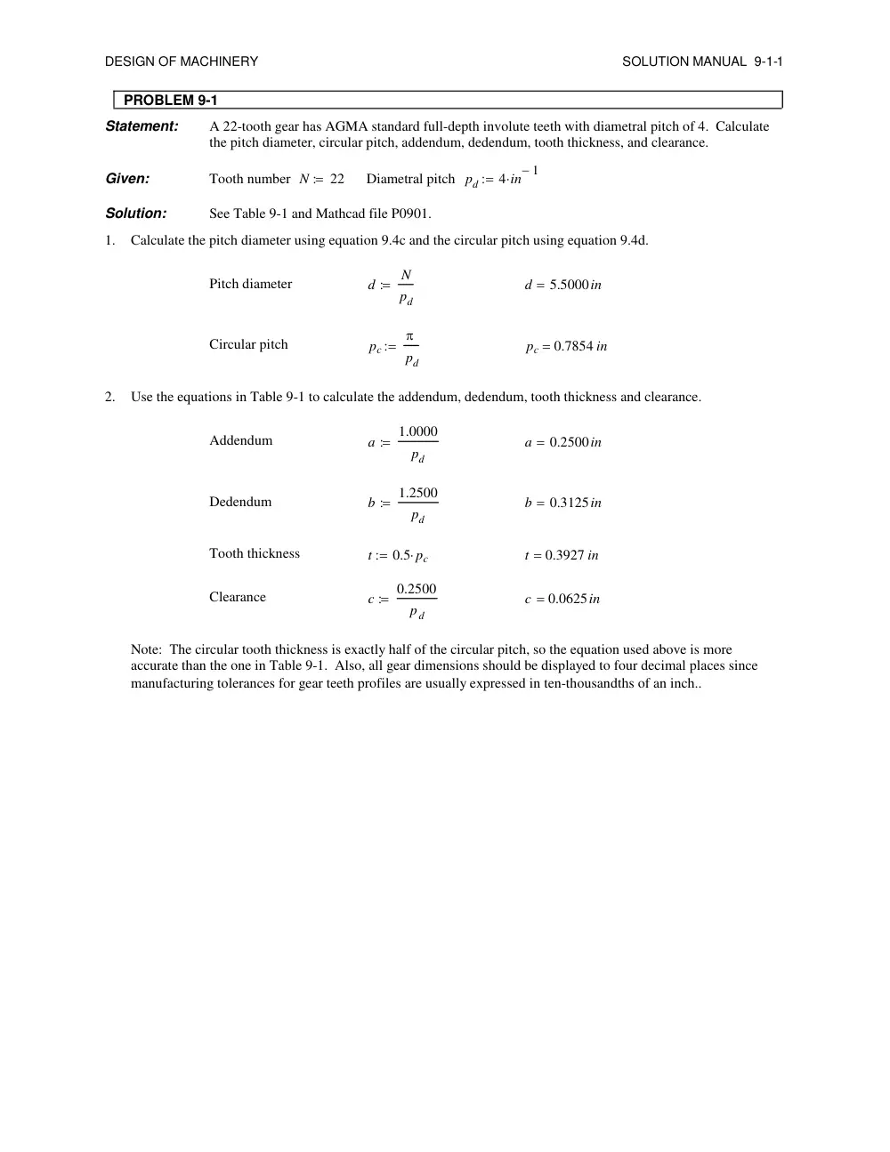
PROBLEM 9-1
Statement:
A 22-tooth gear has AGMA standard full-depth involute teeth with diametral pitch of 4. Calculate
the pitch diameter, circular pitch, addendum, dedendum, tooth thickness, and clearance.
Given:
Tooth number N
22
Diametral pitch pd
4 in
1
Solution:
See Table 9-1 and Mathcad file P0901.
1.
Calculate the pitch diameter using equation 9.4c and the circular pitch using equation 9.4d.
Pitch diameter
d
N
pd
d
5.5000in
Circular pitch
pc
pd
pc
0.7854 in
2.
Use the equations in Table 9-1 to calculate the addendum, dedendum, tooth thickness and clearance.
Addendum
a
1.0000
pd
a
0.2500in
Dedendum
b
1.2500
pd
b
0.3125in
Tooth thickness
t
0.5 pc
t
0.3927 in
Clearance
c
0.2500
p d
c
0.0625in
Note: The circular tooth thickness is exactly half of the circular pitch, so the equation used above is more
accurate than the one in Table 9-1. Also, all gear dimensions should be displayed to four decimal places since
manufacturing tolerances for gear teeth profiles are usually expressed in ten-thousandths of an inch..
DESIGN OF MACHINERY
SOLUTION MANUAL 9-5-1
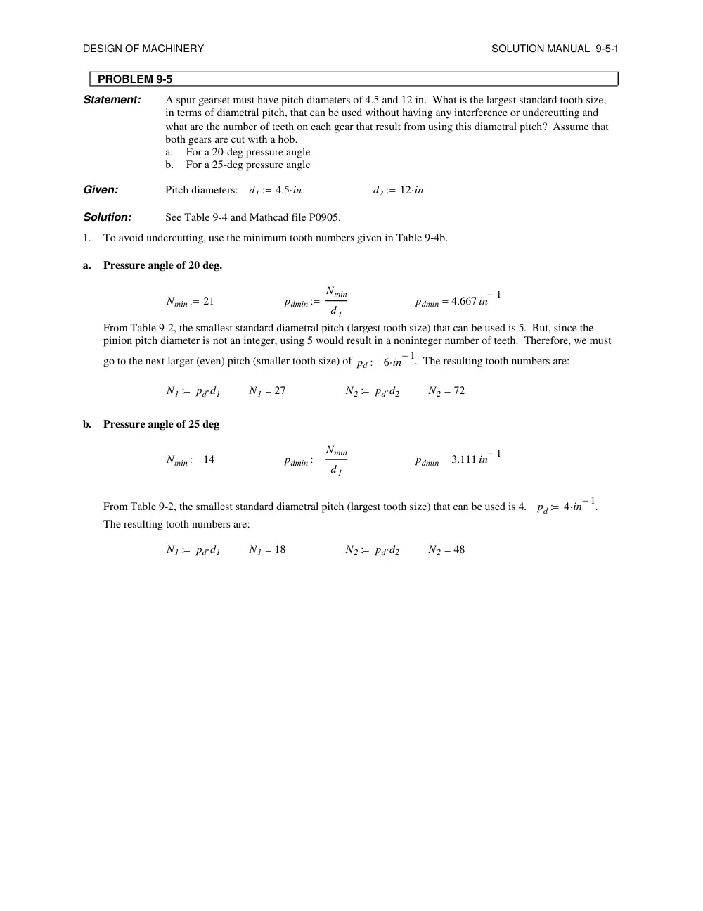
PROBLEM 9-5
Statement:
A spur gearset must have pitch diameters of 4.5 and 12 in. What is the largest standard tooth size,
in terms of diametral pitch, that can be used without having any interference or undercutting and
what are the number of teeth on each gear that result from using this diametral pitch? Assume that
both gears are cut with a hob.
a.
For a 20-deg pressure angle
b.
For a 25-deg pressure angle
Given:
Pitch diameters:
d1
4.5 in
d2
12 in
Solution:
See Table 9-4 and Mathcad file P0905.
1.
To avoid undercutting, use the minimum tooth numbers given in Table 9-4b.
a.
Pressure angle of 20 deg.
Nmin
21
pdmin
Nmin
d 1
pdmin
4.667 in
1
From Table 9-2, the smallest standard diametral pitch (largest tooth size) that can be used is 5. But, since the
pinion pitch diameter is not an integer, using 5 would result in a noninteger number of teeth. Therefore, we must
go to the next larger (even) pitch (smaller tooth size) of pd
6 in
1
. The resulting tooth numbers are:
N1
pd d1
N1
27
N2
pd d2
N2
72
b.
Pressure angle of 25 deg
Nmin
14
pdmin
Nmin
d 1
pdmin
3.111 in
1
From Table 9-2, the smallest standard diametral pitch (largest tooth size) that can be used is 4.
pd
4 in
1
.
The resulting tooth numbers are:
N1
pd d1
N1
18
N2
pd d2
N2
48
DESIGN OF MACHINERY
SOLUTION MANUAL 9-6-1
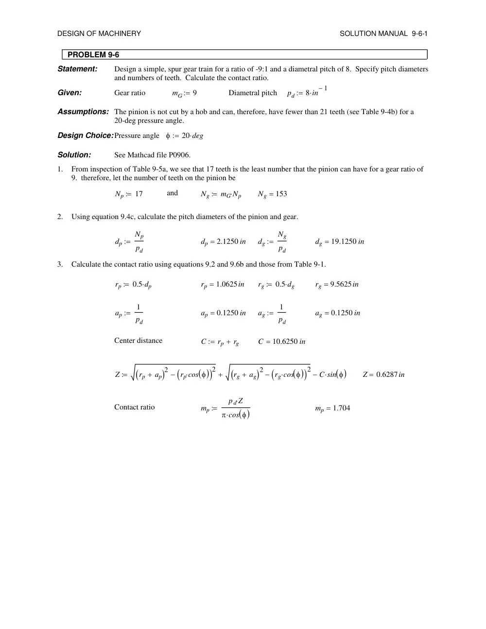
PROBLEM 9-6
Statement:
Design a simple, spur gear train for a ratio of -9:1 and a diametral pitch of 8. Specify pitch diameters
and numbers of teeth. Calculate the contact ratio.
Given:
Gear ratio
mG
9
Diametral pitch
pd
8 in
1
Assumptions: The pinion is not cut by a hob and can, therefore, have fewer than 21 teeth (see Table 9-4b) for a
20-deg pressure angle.
Design Choice:Pressure angle
20 deg
Solution:
See Mathcad file P0906.
1.
From inspection of Table 9-5a, we see that 17 teeth is the least number that the pinion can have for a gear ratio of
9. therefore, let the number of teeth on the pinion be
Np
17
and
Ng
mG Np
Ng
153
2.
Using equation 9.4c, calculate the pitch diameters of the pinion and gear.
dp
Np
pd
dp
2.1250 in
dg
Ng
pd
dg
19.1250 in
3.
Calculate the contact ratio using equations 9.2 and 9.6b and those from Table 9-1.
rp
0.5 dp
rp
1.0625in
rg
0.5 dg
rg
9.5625in
ap
1
pd
ap
0.1250 in
ag
1
pd
ag
0.1250 in
Center distance
C
rp
rg
C
10.6250 in
Z
rp
ap
2
rp cos
2
rg
ag
2
rg cos
2
C sin
Z
0.6287in
Contact ratio
mp
p d Z
cos
mp
1.704
DESIGN OF MACHINERY
SOLUTION MANUAL 9-10-1
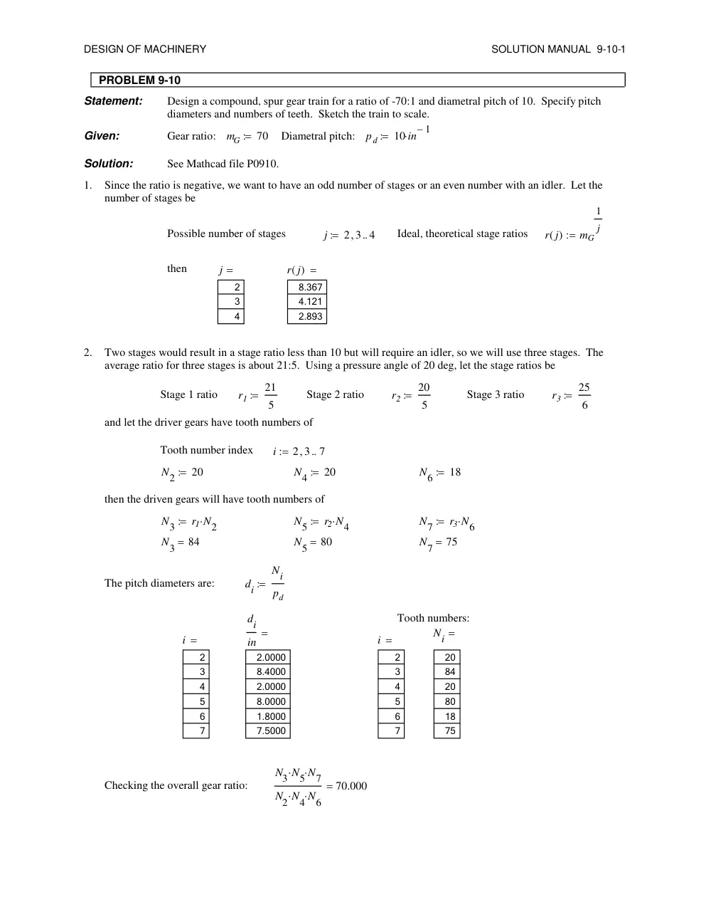
PROBLEM 9-10
Statement:
Design a compound, spur gear train for a ratio of -70:1 and diametral pitch of 10. Specify pitch
diameters and numbers of teeth. Sketch the train to scale.
Given:
Gear ratio:
mG
70
Diametral pitch:
p d
10 in
1
Solution:
See Mathcad file P0910.
1.
Since the ratio is negative, we want to have an odd number of stages or an even number with an idler. Let the
number of stages be
Possible number of stages
j
2 3
4
Ideal, theoretical stage ratios
r j( )
mG
1
j
then
j
2
3
4
r j( )
8.367
4.121
2.893
2.
Two stages would result in a stage ratio less than 10 but will require an idler, so we will use three stages. The
average ratio for three stages is about 21:5. Using a pressure angle of 20 deg, let the stage ratios be
Stage 1 ratio
r1
21
5
Stage 2 ratio
r2
20
5
Stage 3 ratio
r3
25
6
and let the driver gears have tooth numbers of
Tooth number index
i
2 3
7
N2
20
N4
20
N6
18
then the driven gears will have tooth numbers of
N3
r1 N2
N5
r2 N4
N7
r3 N6
N3
84
N5
80
N7
75
The pitch diameters are:
di
Ni
pd
Tooth numbers:
di
in
2.0000
8.4000
2.0000
8.0000
1.8000
7.5000
Ni
20
84
20
80
18
75
i
2
3
4
5
6
7
i
2
3
4
5
6
7
Checking the overall gear ratio:
N3 N5
N7
N2 N4
N6
70.000
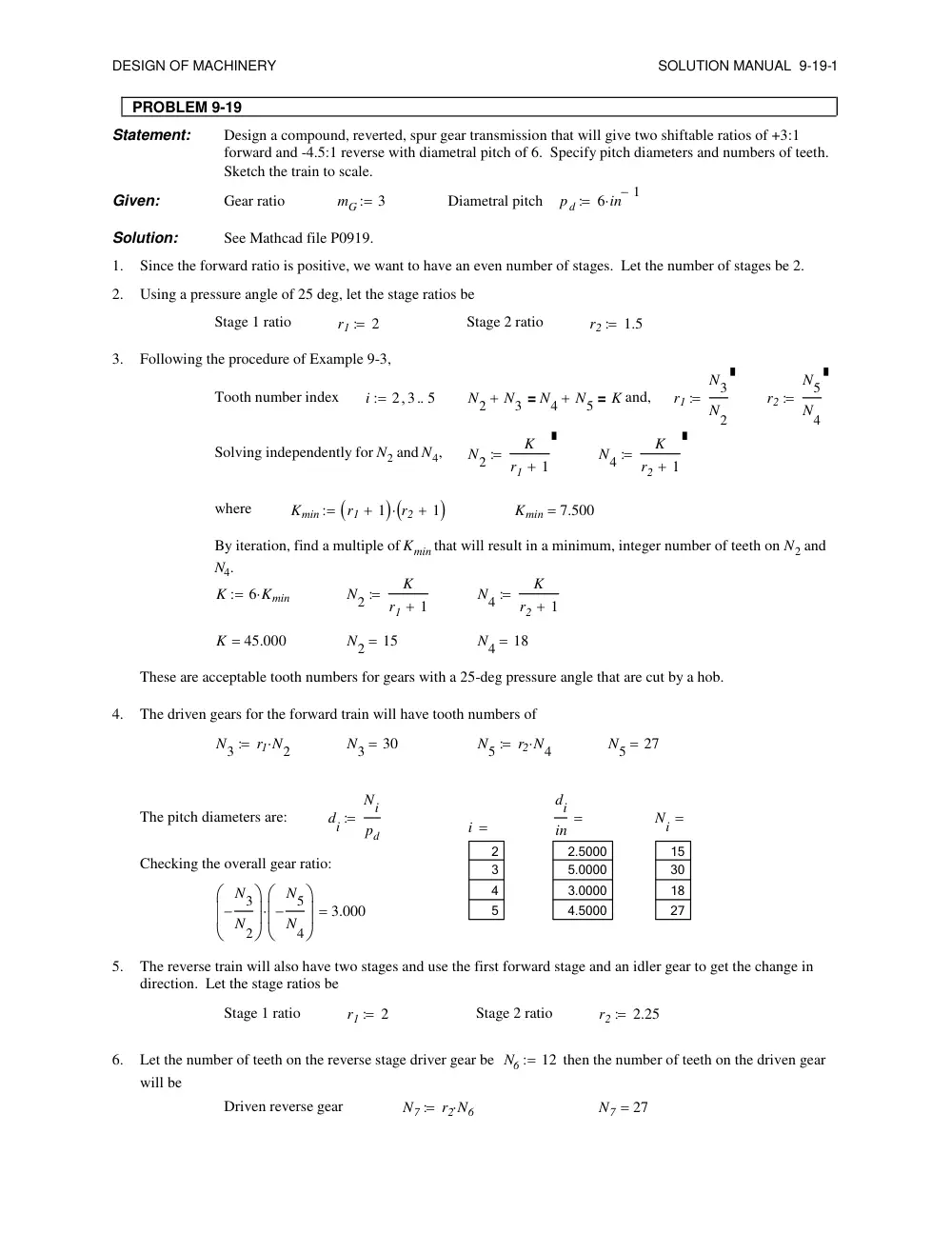
DESIGN OF MACHINERY
SOLUTION MANUAL 9-19-1
PROBLEM 9-19
Statement:
Design a compound, reverted, spur gear transmission that will give two shiftable ratios of +3:1
forward and -4.5:1 reverse with diametral pitch of 6. Specify pitch diameters and numbers of teeth.
Sketch the train to scale.
Given:
Gear ratio
mG
3
Diametral pitch
p d
6 in
1
Solution:
See Mathcad file P0919.
1.
Since the forward ratio is positive, we want to have an even number of stages. Let the number of stages be 2.
2.
Using a pressure angle of 25 deg, let the stage ratios be
Stage 1 ratio
r1
2
Stage 2 ratio
r2
1.5
3.
Following the procedure of Example 9-3,
Tooth number index
i
2 3
5
N2
N3
N4
N5
=
= K
and,
r1
N3
N2
r2
N5
N4
Solving independently for N2 and N4,
N2
K
r1
1
N4
K
r2
1
where
Kmin
r1
1
r2
1
Kmin
7.500
By iteration, find a multiple of Kmin that will result in a minimum, integer number of teeth on N2 and
N4.
K
6 Kmin
N2
K
r1
1
N4
K
r2
1
K
45.000
N2
15
N4
18
These are acceptable tooth numbers for gears with a 25-deg pressure angle that are cut by a hob.
4.
The driven gears for the forward train will have tooth numbers of
N3
r1 N2
N3
30
N5
r2 N4
N5
27
The pitch diameters are:
di
Ni
pd
di
in
2.5000
5.0000
3.0000
4.5000
Ni
15
30
18
27
i
2
3
4
5
Checking the overall gear ratio:
N3
N2
N5
N4
3.000
5.
The reverse train will also have two stages and use the first forward stage and an idler gear to get the change in
direction. Let the stage ratios be
Stage 1 ratio
r1
2
Stage 2 ratio
r2
2.25
6.
Let the number of teeth on the reverse stage driver gear be N6
12
then the number of teeth on the driven gear
will be
Driven reverse gear
N7
r2 N6
N7
27
DESIGN OF MACHINERY
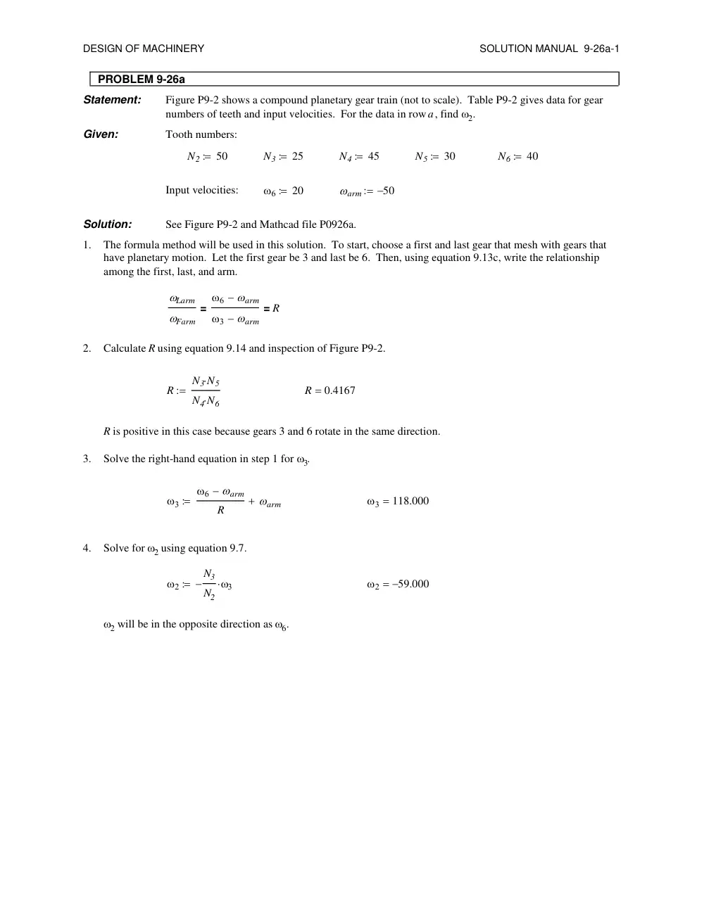
SOLUTION MANUAL 9-26a-1
PROBLEM 9-26a
Statement:
Figure P9-2 shows a compound planetary gear train (not to scale). Table P9-2 gives data for gear
numbers of teeth and input velocities. For the data in row a, find 2.
Given:
Tooth numbers:
N2
50
N3
25
N4
45
N5
30
N6
40
Input velocities:
20
arm
50
Solution:
See Figure P9-2 and Mathcad file P0926a.
1.
The formula method will be used in this solution. To start, choose a first and last gear that mesh with gears that
have planetary motion. Let the first gear be 3 and last be 6. Then, using equation 9.13c, write the relationship
among the first, last, and arm.
Larm
Farm
arm
arm
=
R
=
2.
Calculate R using equation 9.14 and inspection of Figure P9-2.
R
N3 N5
N4 N6
R
0.4167
R is positive in this case because gears 3 and 6 rotate in the same direction.
3.
Solve the right-hand equation in step 1 for 3.
arm
R
arm
118.000
4.
Solve for 2 using equation 9.7.
N3
N2
59.000
2 will be in the opposite direction as 6.
DESIGN OF MACHINERY
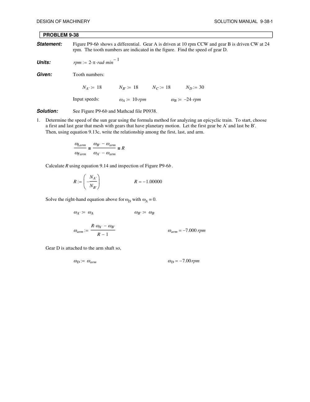
SOLUTION MANUAL 9-38-1
PROBLEM 9-38
Statement:
Figure P9-6b shows a differential. Gear A is driven at 10 rpm CCW and gear B is driven CW at 24
rpm. The tooth numbers are indicated in the figure. Find the speed of gear D.
Units:
rpm
2
rad
min
1
Given:
Tooth numbers:
NA'
18
NB'
18
NC
18
ND
30
Input speeds:
A
10 rpm
B
24
rpm
Solution:
See Figure P9-6b and Mathcad file P0938.
1.
Determine the speed of the sun gear using the formula method for analyzing an epicyclic train. To start, choose
a first and last gear that mesh with gears that have planetary motion. Let the first gear be A' and last be B'.
Then, using equation 9.13c, write the relationship among the first, last, and arm.
Larm
Farm
B'
arm
A'
arm
=
R
=
Calculate R using equation 9.14 and inspection of Figure P9-6b.
R
NA'
NB'
R
1.00000
Solve the right-hand equation above for D with A = 0.
A'
A
B'
B
arm
R A'
B'
R
1
arm
7.000
rpm
Gear D is attached to the arm shaft so,
D
arm
D
7.00
rpm
DESIGN OF MACHINERY
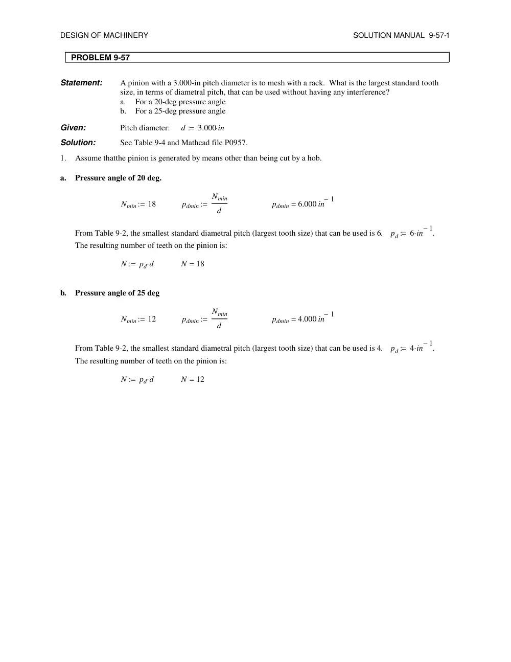
SOLUTION MANUAL 9-57-1
PROBLEM 9-57
Statement:
A pinion with a 3.000-in pitch diameter is to mesh with a rack. What is the largest standard tooth
size, in terms of diametral pitch, that can be used without having any interference?
a.
For a 20-deg pressure angle
b.
For a 25-deg pressure angle
Given:
Pitch diameter:
d
3.000 in
Solution:
See Table 9-4 and Mathcad file P0957.
1.
Assume thatthe pinion is generated by means other than being cut by a hob.
a.
Pressure angle of 20 deg.
Nmin
18
pdmin
Nmin
d
pdmin
6.000 in
1
From Table 9-2, the smallest standard diametral pitch (largest tooth size) that can be used is 6.
pd
6 in
1
.
The resulting number of teeth on the pinion is:
N
pd d
N
18
b.
Pressure angle of 25 deg
Nmin
12
pdmin
Nmin
d
pdmin
4.000 in
1
From Table 9-2, the smallest standard diametral pitch (largest tooth size) that can be used is 4.
pd
4 in
1
.
The resulting number of teeth on the pinion is:
N
pd d
N
12
DESIGN OF MACHINERY
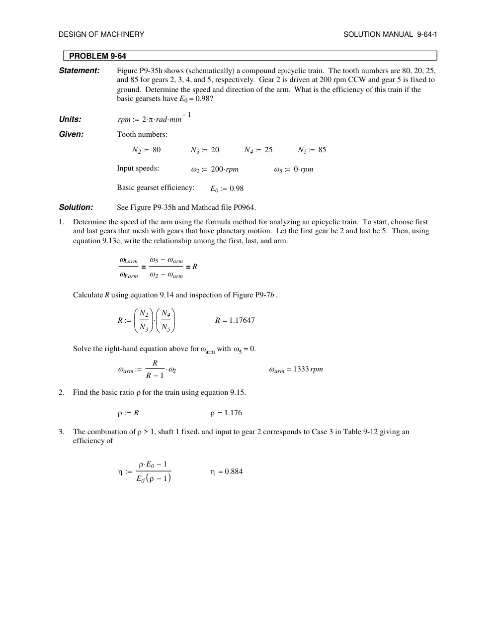
SOLUTION MANUAL 9-64-1
PROBLEM 9-64
Statement:
Figure P9-35h shows (schematically) a compound epicyclic train. The tooth numbers are 80, 20, 25,
and 85 for gears 2, 3, 4, and 5, respectively. Gear 2 is driven at 200 rpm CCW and gear 5 is fixed to
ground. Determine the speed and direction of the arm. What is the efficiency of this train if the
basic gearsets have E0 = 0.98?
Units:
rpm
2
rad
min
1
Given:
Tooth numbers:
N2
80
N3
20
N4
25
N5
85
Input speeds:
2
200 rpm
5
0 rpm
Basic gearset efficiency:
E0
0.98
Solution:
See Figure P9-35h and Mathcad file P0964.
1.
Determine the speed of the arm using the formula method for analyzing an epicyclic train. To start, choose first
and last gears that mesh with gears that have planetary motion. Let the first gear be 2 and last be 5. Then, using
equation 9.13c, write the relationship among the first, last, and arm.
Larm
Farm
5
arm
2
arm
=
R
=
Calculate R using equation 9.14 and inspection of Figure P9-7b.
R
N2
N3
N4
N5
R
1.17647
Solve the right-hand equation above for arm with = 0.
arm
R
R
1
2
arm
1333rpm
2.
Find the basic ratio for the train using equation 9.15.
R
1.176
3.
The combination of > 1, shaft 1 fixed, and input to gear 2 corresponds to Case 3 in Table 9-12 giving an
efficiency of
E0
1
E0
1
0.884