
CEN 202 Problems All Chapters, Spring 2001
Notre Dame University–Louaize · Statics · 130 pages

Showing the first 10 of 130 pages. Download the PDF to see all of it.
More CEN 202 files
- Exam 1 · Summer 2016ExamView
- Exam 2 Sample · Summer 2013ExamView
- Exam 2 · Spring 2013ExamView
- Problems Additional EXER with Sol · Fall 2013Problems · with solutionView
- Exam 2 · Spring 2012ExamView
- Exam 1 with Solution · Spring 2010Exam · with solutionView
- Exam 2 with Solution · Spring 2010Exam · with solutionView
- Exam 1 · Spring 2009ExamView
Show the text of this chapter
190
© 2010 Pearson Education, Inc., Upper Saddle River, NJ. All rights reserved.This material is protected under all copyright laws as they currently
exist. No portion of this material may be reproduced, in any form or by any means, without permission in writing from the publisher.
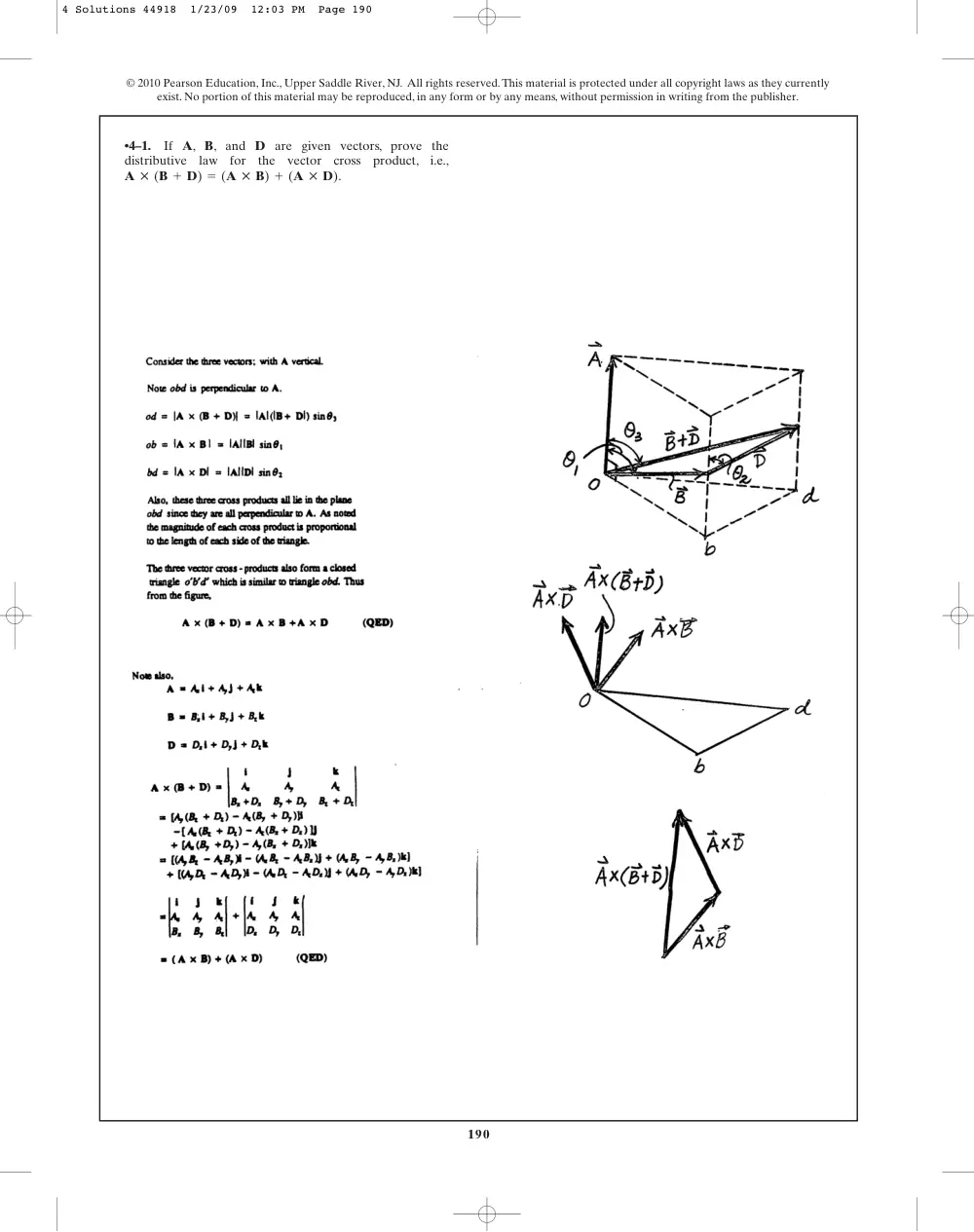
•4–1.
If A, B, and D are given vectors, prove the
distributive law for the vector cross product,
i.e.,
.
A : (B + D) = (A : B) + (A : D)
4 Solutions 44918 1/23/09 12:03 PM Page 190
191
© 2010 Pearson Education, Inc., Upper Saddle River, NJ. All rights reserved.This material is protected under all copyright laws as they currently
exist. No portion of this material may be reproduced, in any form or by any means, without permission in writing from the publisher.
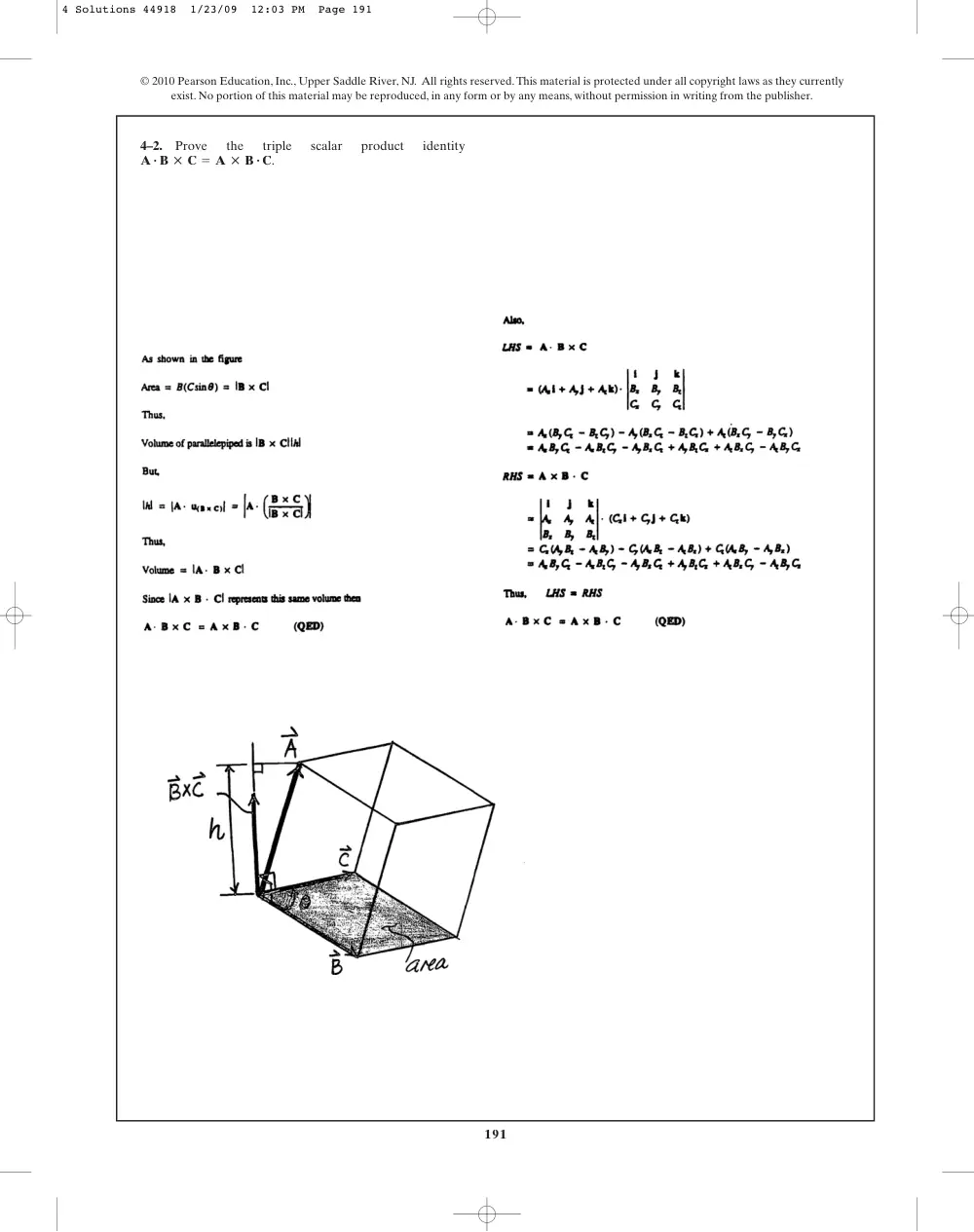
4–2.
Prove
the
triple
scalar
product
identity
.
A # B : C = A : B # C
4 Solutions 44918 1/23/09 12:03 PM Page 191
192
© 2010 Pearson Education, Inc., Upper Saddle River, NJ. All rights reserved.This material is protected under all copyright laws as they currently
exist. No portion of this material may be reproduced, in any form or by any means, without permission in writing from the publisher.
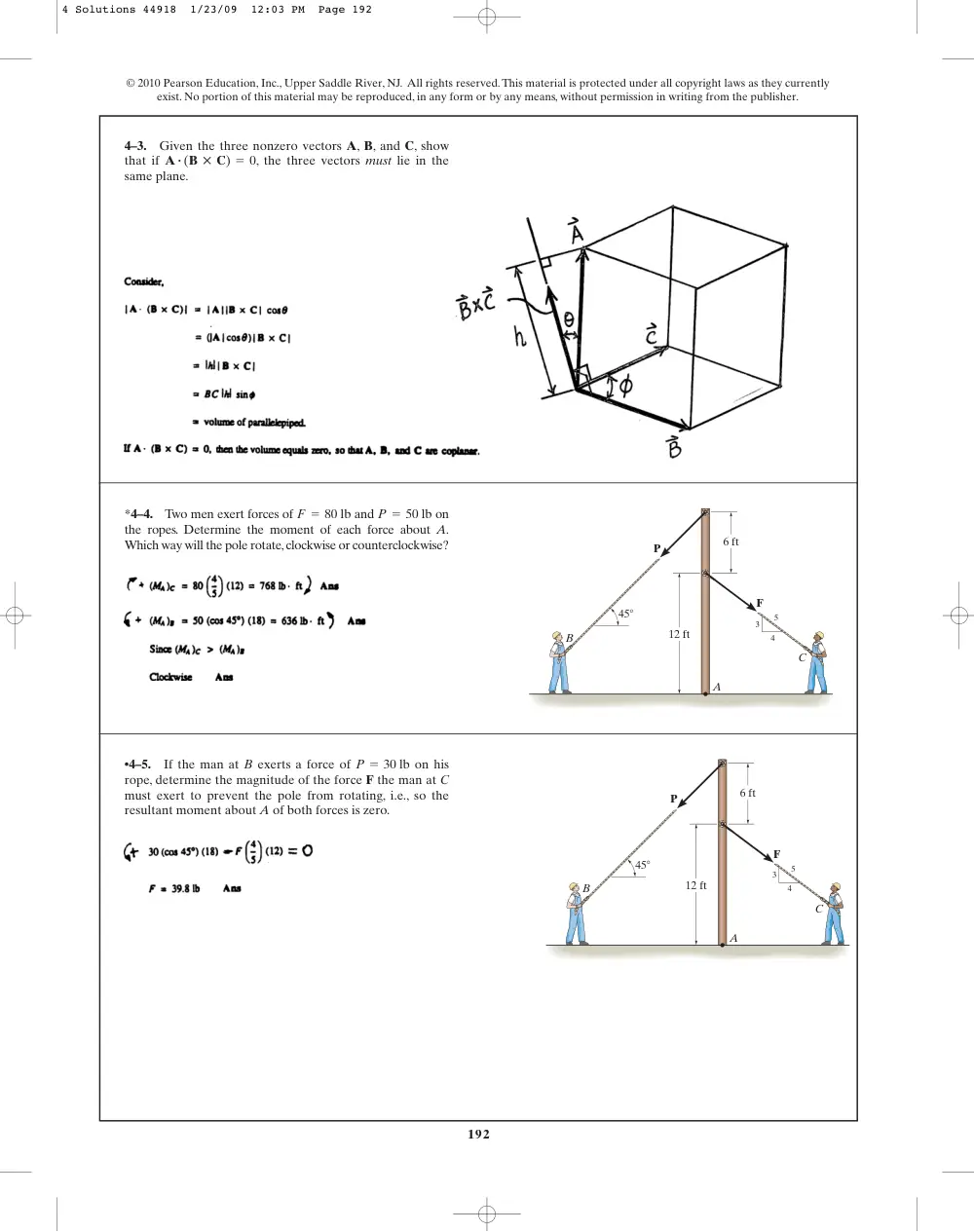
4–3.
Given the three nonzero vectors A, B, and C, show
that if
, the three vectors must lie in the
same plane.
A # (B : C) = 0
*4–4.
Two men exert forces of
and
on
the ropes. Determine the moment of each force about A.
Which way will the pole rotate,clockwise or counterclockwise?
P = 50 lb
F = 80 lb
A
P
F
B
C
6 ft
45�
12 ft
3
4
5
•4–5.
If the man at B exerts a force of
on his
rope, determine the magnitude of the force F the man at C
must exert to prevent the pole from rotating, i.e., so the
resultant moment about A of both forces is zero.
P = 30 lb
A
P
F
B
C
6 ft
45�
12 ft
3
4
5
4 Solutions 44918 1/23/09 12:03 PM Page 192
193
© 2010 Pearson Education, Inc., Upper Saddle River, NJ. All rights reserved.This material is protected under all copyright laws as they currently
exist. No portion of this material may be reproduced, in any form or by any means, without permission in writing from the publisher.
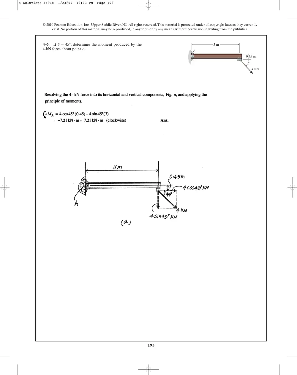
4–6.
If
, determine the moment produced by the
4-kN force about point A.
u = 45°
3 m
0.45 m
4 kN
A
u
4 Solutions 44918 1/23/09 12:03 PM Page 193
194
© 2010 Pearson Education, Inc., Upper Saddle River, NJ. All rights reserved.This material is protected under all copyright laws as they currently
exist. No portion of this material may be reproduced, in any form or by any means, without permission in writing from the publisher.
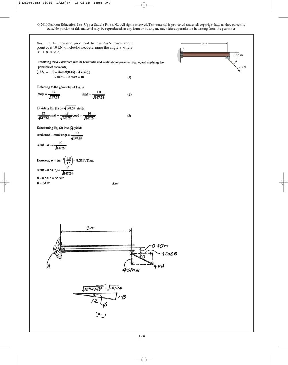
4–7.
If the moment produced by the 4-kN force about
point A is
clockwise, determine the angle , where
0° … u … 90°.
u
10 kN # m
3 m
0.45 m
4 kN
A
u
4 Solutions 44918 1/23/09 12:03 PM Page 194
195
© 2010 Pearson Education, Inc., Upper Saddle River, NJ. All rights reserved.This material is protected under all copyright laws as they currently
exist. No portion of this material may be reproduced, in any form or by any means, without permission in writing from the publisher.
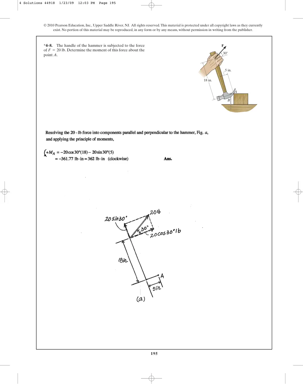
*4–8.
The handle of the hammer is subjected to the force
of
Determine the moment of this force about the
point A.
F = 20 lb.
F
B
A
18 in.
5 in.
30�
4 Solutions 44918 1/23/09 12:03 PM Page 195
196
© 2010 Pearson Education, Inc., Upper Saddle River, NJ. All rights reserved.This material is protected under all copyright laws as they currently
exist. No portion of this material may be reproduced, in any form or by any means, without permission in writing from the publisher.
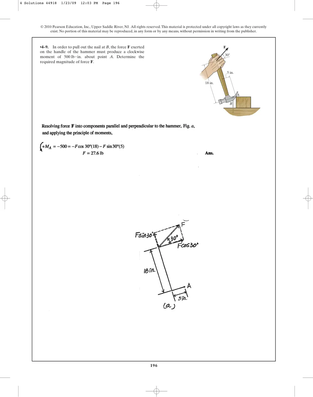
•4–9.
In order to pull out the nail at B, the force F exerted
on the handle of the hammer must produce a clockwise
moment of
about point A. Determine the
required magnitude of force F.
500 lb # in.
F
B
A
18 in.
5 in.
30�
4 Solutions 44918 1/23/09 12:03 PM Page 196
197
© 2010 Pearson Education, Inc., Upper Saddle River, NJ. All rights reserved.This material is protected under all copyright laws as they currently
exist. No portion of this material may be reproduced, in any form or by any means, without permission in writing from the publisher.
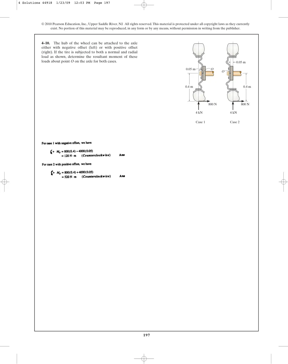
4–10.
The hub of the wheel can be attached to the axle
either with negative offset (left) or with positive offset
(right). If the tire is subjected to both a normal and radial
load as shown, determine the resultant moment of these
loads about point O on the axle for both cases.
4 kN
800 N
800 N
4 kN
Case 1
Case 2
0.4 m
0.05 m
0.05 m
0.4 m
O
O
4 Solutions 44918 1/23/09 12:03 PM Page 197
198
© 2010 Pearson Education, Inc., Upper Saddle River, NJ. All rights reserved.This material is protected under all copyright laws as they currently
exist. No portion of this material may be reproduced, in any form or by any means, without permission in writing from the publisher.
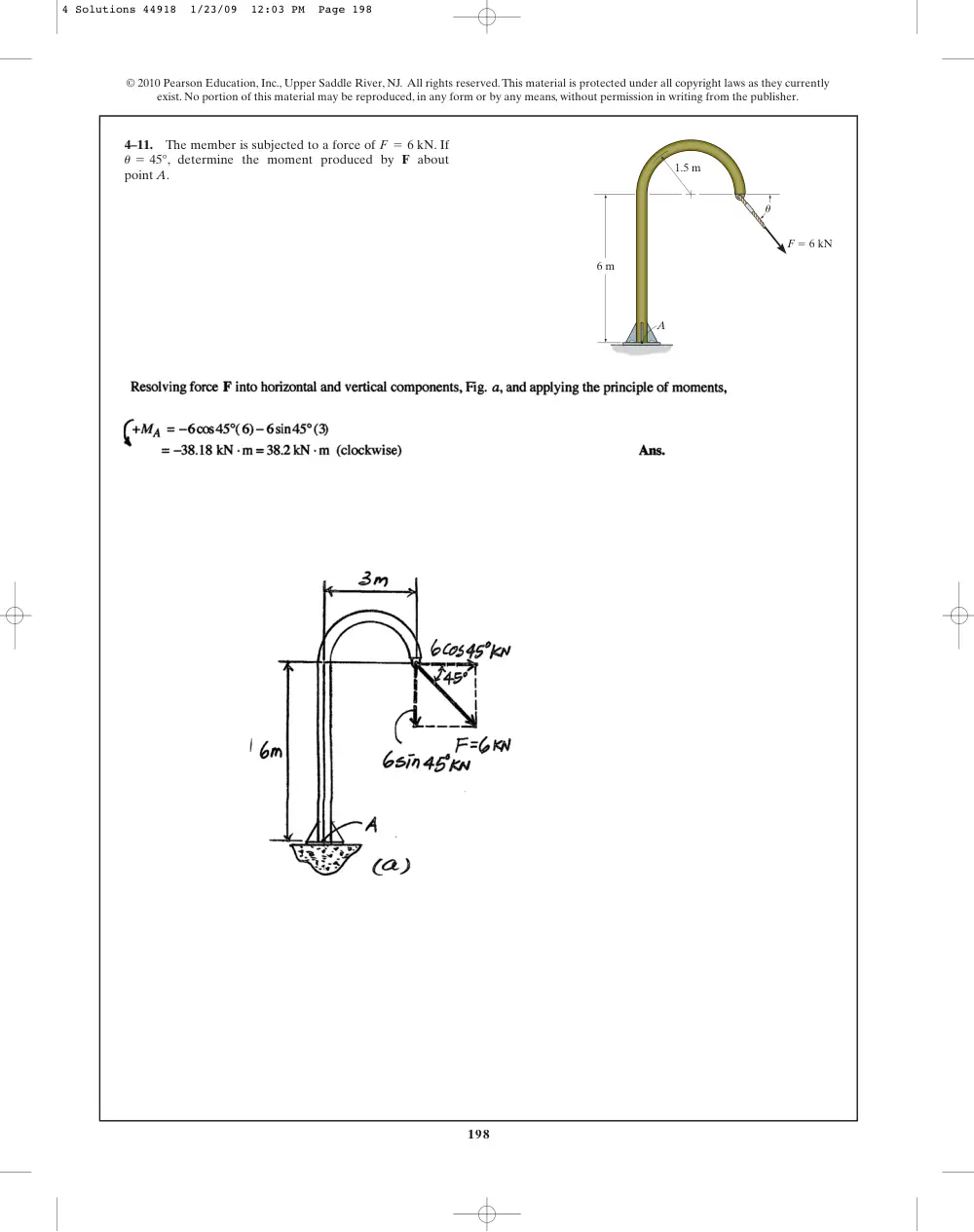
4–11.
The member is subjected to a force of
. If
, determine the moment produced by F about
point A.
u = 45°
F = 6 kN
A
6 m
1.5 m
u
F � 6 kN
4 Solutions 44918 1/23/09 12:03 PM Page 198
199
© 2010 Pearson Education, Inc., Upper Saddle River, NJ. All rights reserved.This material is protected under all copyright laws as they currently
exist. No portion of this material may be reproduced, in any form or by any means, without permission in writing from the publisher.
*4–12.
Determine the angle
of the
force F so that it produces a maximum moment and a
minimum moment about point A. Also, what are the
magnitudes of these maximum and minimum moments?
u (0° … u … 180°)
A
6 m
1.5 m
u
F � 6 kN
4 Solutions 44918 1/23/09 12:03 PM Page 199
200
© 2010 Pearson Education, Inc., Upper Saddle River, NJ. All rights reserved.This material is protected under all copyright laws as they currently
exist. No portion of this material may be reproduced, in any form or by any means, without permission in writing from the publisher.
•4–13.
Determine the moment produced by the force F
about point A in terms of the angle . Plot the graph of
versus , where
0° … u … 180°.
u
MA
u
A
6 m
1.5 m
u
F � 6 kN
4 Solutions 44918 1/23/09 12:03 PM Page 200
201
© 2010 Pearson Education, Inc., Upper Saddle River, NJ. All rights reserved.This material is protected under all copyright laws as they currently
exist. No portion of this material may be reproduced, in any form or by any means, without permission in writing from the publisher.
4–14.
Serious neck injuries can occur when a football
player is struck in the face guard of his helmet in the
manner shown, giving rise to a guillotine mechanism.
Determine the moment of the knee force
about
point A. What would be the magnitude of the neck force F
so that it gives the counterbalancing moment about A?
P = 50 lb
2 in.
4 in.
6 in.
30�
60�
P � 50 lb
F
A
4–15.
The Achilles tendon force of
is
mobilized when the man tries to stand on his toes.As this is
done, each of his feet is subjected to a reactive force of
Determine the resultant moment of
and
about the ankle joint A.
Nf
Ft
Nf = 400 N.
Ft = 650 N
100 mm
65 mm
200 mm
A
Nf � 400 N
Ft
5�
4 Solutions 44918 1/23/09 12:03 PM Page 201
202
© 2010 Pearson Education, Inc., Upper Saddle River, NJ. All rights reserved.This material is protected under all copyright laws as they currently
exist. No portion of this material may be reproduced, in any form or by any means, without permission in writing from the publisher.
*4–16.
The Achilles tendon force
is mobilized when the
man tries to stand on his toes.As this is done, each of his feet
is subjected to a reactive force of
If the resultant
moment produced by forces
and
about the ankle joint
A is required to be zero, determine the magnitude of
Ft.
Nt
Ft
Nt = 400 N.
Ft
100 mm
65 mm
200 mm
A
Nf � 400 N
Ft
5�
•4–17.
The two boys push on the gate with forces of
and as shown. Determine the moment of each
force about C. Which way will the gate rotate, clockwise or
counterclockwise? Neglect the thickness of the gate.
FA = 30 lb
60�
6 ft
C
B
A
3 ft
3
4
5
FB
FA
4–18.
Two boys push on the gate as shown. If the boy at B
exerts a force of
, determine the magnitude of
the force
the boy at A must exert in order to prevent the
gate from turning. Neglect the thickness of the gate.
FA
FB = 30 lb
60�
6 ft
C
B
A
3 ft
3
4
5
FB
FA
4 Solutions 44918 1/23/09 12:03 PM Page 202
203
© 2010 Pearson Education, Inc., Upper Saddle River, NJ. All rights reserved.This material is protected under all copyright laws as they currently
exist. No portion of this material may be reproduced, in any form or by any means, without permission in writing from the publisher.
4–19.
The tongs are used to grip the ends of the drilling
pipe P. Determine the torque (moment)
that the
applied force
exerts on the pipe about point P
as a function of
. Plot this moment
versus
for
0 … u … 90°.
u
MP
u
F = 150 lb
MP
43 in.
6 in.
F
P
MP
u
*4–20.
The tongs are used to grip the ends of the drilling
pipe P. If a torque (moment) of
is needed
at P to turn the pipe, determine the cable force F that must
be applied to the tongs. Set
.
u = 30°
MP = 800 lb # ft
43 in.
6 in.
F
P
MP
u
4 Solutions 44918 1/23/09 12:03 PM Page 203
204
© 2010 Pearson Education, Inc., Upper Saddle River, NJ. All rights reserved.This material is protected under all copyright laws as they currently
exist. No portion of this material may be reproduced, in any form or by any means, without permission in writing from the publisher.
•4–21.
Determine the direction for
of the
force F so that it produces the maximum moment about
point A. Calculate this moment.
0° … u … 180°
u
F � 400 N
3 m
2 m
A
u
4 Solutions 44918 1/23/09 12:03 PM Page 204
205
© 2010 Pearson Education, Inc., Upper Saddle River, NJ. All rights reserved.This material is protected under all copyright laws as they currently
exist. No portion of this material may be reproduced, in any form or by any means, without permission in writing from the publisher.
4–22.
Determine the moment of the force F about point A
as a function of . Plot the results of M (ordinate) versus
(abscissa) for
0° … u … 180°.
u
u
F � 400 N
3 m
2 m
A
u
4–23.
Determine the minimum moment produced by
the force F about point A. Specify the angle
u … 180°).
u (0° …
F � 400 N
3 m
2 m
A
u
4 Solutions 44918 1/23/09 12:03 PM Page 205
206
© 2010 Pearson Education, Inc., Upper Saddle River, NJ. All rights reserved.This material is protected under all copyright laws as they currently
exist. No portion of this material may be reproduced, in any form or by any means, without permission in writing from the publisher.
*4–24.
In order to raise the lamp post from the position
shown, force F is applied to the cable. If
determine the moment produced by F about point A.
F = 200 lb,
F
75�
C
A
B
10 ft
20 ft
4 Solutions 44918 1/23/09 12:03 PM Page 206
207
© 2010 Pearson Education, Inc., Upper Saddle River, NJ. All rights reserved.This material is protected under all copyright laws as they currently
exist. No portion of this material may be reproduced, in any form or by any means, without permission in writing from the publisher.
•4–25.
In order to raise the lamp post from the position
shown,the force F on the cable must create a counterclockwise
moment of
about point A. Determine the
magnitude of F that must be applied to the cable.
1500 lb # ft
F
75�
C
A
B
10 ft
20 ft
4 Solutions 44918 1/23/09 12:03 PM Page 207
208
© 2010 Pearson Education, Inc., Upper Saddle River, NJ. All rights reserved.This material is protected under all copyright laws as they currently
exist. No portion of this material may be reproduced, in any form or by any means, without permission in writing from the publisher.
4–26.
The foot segment is subjected to the pull of the two
plantarflexor muscles. Determine the moment of each force
about the point of contact A on the ground.
60�
30�
4 in.
A
1 in.
3.5 in.
70�
F2 � 30 lb
F1 � 20 lb
4–27.
The 70-N force acts on the end of the pipe at B.
Determine (a) the moment of this force about point A, and
(b) the magnitude and direction of a horizontal force,applied
at C, which produces the same moment.Take u = 60°.
A
C
0.3 m
0.7 m
0.9 m
B
70 N
u
4 Solutions 44918 1/23/09 12:03 PM Page 208
209
© 2010 Pearson Education, Inc., Upper Saddle River, NJ. All rights reserved.This material is protected under all copyright laws as they currently
exist. No portion of this material may be reproduced, in any form or by any means, without permission in writing from the publisher.
*4–28.
The 70-N force acts on the end of the pipe at B.
Determine the angles
of the force that
will produce maximum and minimum moments about
point A.What are the magnitudes of these moments?
u 10° … u … 180°2
A
C
0.3 m
0.7 m
0.9 m
B
70 N
u
•4–29.
Determine the moment of each force about the
bolt located at A.Take FB = 40 lb, FC = 50 lb.
4 Solutions 44918 1/23/09 12:03 PM Page 209
210
© 2010 Pearson Education, Inc., Upper Saddle River, NJ. All rights reserved.This material is protected under all copyright laws as they currently
exist. No portion of this material may be reproduced, in any form or by any means, without permission in writing from the publisher.
4–30.
If
and
determine the resultant
moment about the bolt located at A.
FC = 45 lb,
FB = 30 lb
4–31.
The rod on the power control mechanism for a
business jet is subjected to a force of 80 N. Determine the
moment of this force about the bearing at A.
20�
60�
A
80 N
150 mm
*4–32.
The towline exerts a force of
at the end
of the 20-m-long crane boom. If
determine the
placement x of the hook at A so that this force creates a
maximum moment about point O.What is this moment?
u = 30°,
P = 4 kN
1.5 m
O
20 m
A
B
P � 4 kN
x
u
4 Solutions 44918 1/23/09 12:03 PM Page 210
211
© 2010 Pearson Education, Inc., Upper Saddle River, NJ. All rights reserved.This material is protected under all copyright laws as they currently
exist. No portion of this material may be reproduced, in any form or by any means, without permission in writing from the publisher.
•4–33.
The towline exerts a force of
at the end
of the 20-m-long crane boom. If
determine the
position of the boom so that this force creates a maximum
moment about point O.What is this moment?
u
x = 25 m,
P = 4 kN
1.5 m
O
20 m
A
B
P � 4 kN
x
u
4 Solutions 44918 1/23/09 12:03 PM Page 211
212
© 2010 Pearson Education, Inc., Upper Saddle River, NJ. All rights reserved.This material is protected under all copyright laws as they currently
exist. No portion of this material may be reproduced, in any form or by any means, without permission in writing from the publisher.
4–34.
In order to hold the wheelbarrow in the position
shown, force F must produce a counterclockwise moment
of
about the axle at A. Determine the required
magnitude of force F.
200 N # m
B
0.65 m
0.5 m
1.2 m
30�
0.3 m
F
G
A
4 Solutions 44918 1/23/09 12:03 PM Page 212
213
© 2010 Pearson Education, Inc., Upper Saddle River, NJ. All rights reserved.This material is protected under all copyright laws as they currently
exist. No portion of this material may be reproduced, in any form or by any means, without permission in writing from the publisher.
4–35.
The wheelbarrow and its contents have a mass of
50 kg and a center of mass at G. If the resultant moment
produced by force F and the weight about point A is to be
zero, determine the required magnitude of force F.
B
0.65 m
0.5 m
1.2 m
30�
0.3 m
F
G
A
4 Solutions 44918 1/23/09 12:03 PM Page 213
214
© 2010 Pearson Education, Inc., Upper Saddle River, NJ. All rights reserved.This material is protected under all copyright laws as they currently
exist. No portion of this material may be reproduced, in any form or by any means, without permission in writing from the publisher.
*4–36.
The wheelbarrow and its contents have a center of
mass at G. If
and the resultant moment produced
by force F and the weight about the axle at A is zero,
determine the mass of the wheelbarrow and its contents.
F = 100 N
B
0.65 m
0.5 m
1.2 m
30�
0.3 m
F
G
A
4 Solutions 44918 1/23/09 12:03 PM Page 214
215
© 2010 Pearson Education, Inc., Upper Saddle River, NJ. All rights reserved.This material is protected under all copyright laws as they currently
exist. No portion of this material may be reproduced, in any form or by any means, without permission in writing from the publisher.
•4–37.
Determine the moment produced by
about
point O. Express the result as a Cartesian vector.
F1
y
x
z
1 ft
2 ft
2 ft
A
O
3 ft
F2 � {�10i � 30j � 50k} lb
F1 � {�20i � 10j � 30k} lb
4 Solutions 44918 1/23/09 12:03 PM Page 215
216
© 2010 Pearson Education, Inc., Upper Saddle River, NJ. All rights reserved.This material is protected under all copyright laws as they currently
exist. No portion of this material may be reproduced, in any form or by any means, without permission in writing from the publisher.
4–38.
Determine the moment produced by
about
point O. Express the result as a Cartesian vector.
F2
y
x
z
1 ft
2 ft
2 ft
A
O
3 ft
F2 � {�10i � 30j � 50k} lb
F1 � {�20i � 10j � 30k} lb
4 Solutions 44918 1/23/09 12:03 PM Page 216
217
© 2010 Pearson Education, Inc., Upper Saddle River, NJ. All rights reserved.This material is protected under all copyright laws as they currently
exist. No portion of this material may be reproduced, in any form or by any means, without permission in writing from the publisher.
4–39.
Determine the resultant moment produced by the two
forces about point O. Express the result as a Cartesian vector.
y
x
z
1 ft
2 ft
2 ft
A
O
3 ft
F2 � {�10i � 30j � 50k} lb
F1 � {�20i � 10j � 30k} lb
4 Solutions 44918 1/23/09 12:03 PM Page 217
218
© 2010 Pearson Education, Inc., Upper Saddle River, NJ. All rights reserved.This material is protected under all copyright laws as they currently
exist. No portion of this material may be reproduced, in any form or by any means, without permission in writing from the publisher.
*4–40.
Determine the moment produced by force
about point O. Express the result as a Cartesian vector.
FB
y
x
z
C
O
B
A
6 m
3 m
2 m
2.5 m
FC � 420 N
FB � 780 N
4 Solutions 44918 1/23/09 12:03 PM Page 218
219
© 2010 Pearson Education, Inc., Upper Saddle River, NJ. All rights reserved.This material is protected under all copyright laws as they currently
exist. No portion of this material may be reproduced, in any form or by any means, without permission in writing from the publisher.
•4–41.
Determine the moment produced by force
about point O. Express the result as a Cartesian vector.
FC
y
x
z
C
O
B
A
6 m
3 m
2 m
2.5 m
FC � 420 N
FB � 780 N
4 Solutions 44918 1/23/09 12:03 PM Page 219
220
© 2010 Pearson Education, Inc., Upper Saddle River, NJ. All rights reserved.This material is protected under all copyright laws as they currently
exist. No portion of this material may be reproduced, in any form or by any means, without permission in writing from the publisher.
4–42.
Determine the resultant moment produced by
forces
and
about point O. Express the result as a
Cartesian vector.
FC
FB
y
x
z
C
O
B
A
6 m
3 m
2 m
2.5 m
FC � 420 N
FB � 780 N
4 Solutions 44918 1/23/09 12:03 PM Page 220
221
© 2010 Pearson Education, Inc., Upper Saddle River, NJ. All rights reserved.This material is protected under all copyright laws as they currently
exist. No portion of this material may be reproduced, in any form or by any means, without permission in writing from the publisher.
4–43.
Determine the moment produced by each force
about point O located on the drill bit. Express the results as
Cartesian vectors.
x
z
A
B
O
y
150 mm
600 mm
300 mm
150 mm
FA � {�40i � 100j � 60k} N
FB � {�50i � 120j � 60k} N
4 Solutions 44918 1/23/09 12:03 PM Page 221
222
© 2010 Pearson Education, Inc., Upper Saddle River, NJ. All rights reserved.This material is protected under all copyright laws as they currently
exist. No portion of this material may be reproduced, in any form or by any means, without permission in writing from the publisher.
*4–44.
A force of
produces a
moment of
about the origin
of coordinates, point O. If the force acts at a point having an
x coordinate of
determine the y and z coordinates.
x = 1 m,
MO = 54i + 5j - 14k6 kN # m
F = 56i - 2j + 1k6 kN
•4–45.
The pipe assembly is subjected to the 80-N force.
Determine the moment of this force about point A.
400 mm
y
300 mm
200 mm
250 mm
x
z
30�
40�
F � 80 N
B
C
A
4 Solutions 44918 1/23/09 12:03 PM Page 222
223
© 2010 Pearson Education, Inc., Upper Saddle River, NJ. All rights reserved.This material is protected under all copyright laws as they currently
exist. No portion of this material may be reproduced, in any form or by any means, without permission in writing from the publisher.
4–47.
The
force
creates
a
moment about point O of
.
If the force passes through a point having an x coordinate of
1 m, determine the y and z coordinates of the point. Also,
realizing that
, determine the perpendicular
distance d from point O to the line of action of F.
MO = Fd
MO = 5-14i + 8j + 2k6 N # m
F = 56i + 8j + 10k6 N
d
z
x
y
O
y
1 m
z
P
F
MO
4–46.
The pipe assembly is subjected to the 80-N force.
Determine the moment of this force about point B.
400 mm
y
300 mm
200 mm
250 mm
x
z
30�
40�
F � 80 N
B
C
A
4 Solutions 44918 1/23/09 12:03 PM Page 223
224
© 2010 Pearson Education, Inc., Upper Saddle River, NJ. All rights reserved.This material is protected under all copyright laws as they currently
exist. No portion of this material may be reproduced, in any form or by any means, without permission in writing from the publisher.
*4–48.
Force F acts perpendicular to the inclined plane.
Determine the moment produced by F about point A.
Express the result as a Cartesian vector.
z
x
y
3 m
3 m
4 m
A
B
C
F � 400 N
4 Solutions 44918 1/23/09 12:03 PM Page 224
225
© 2010 Pearson Education, Inc., Upper Saddle River, NJ. All rights reserved.This material is protected under all copyright laws as they currently
exist. No portion of this material may be reproduced, in any form or by any means, without permission in writing from the publisher.
•4–49.
Force F acts perpendicular to the inclined plane.
Determine the moment produced by F about point B.
Express the result as a Cartesian vector.
z
x
y
3 m
3 m
4 m
A
B
C
F � 400 N
4 Solutions 44918 1/23/09 12:03 PM Page 225
226
© 2010 Pearson Education, Inc., Upper Saddle River, NJ. All rights reserved.This material is protected under all copyright laws as they currently
exist. No portion of this material may be reproduced, in any form or by any means, without permission in writing from the publisher.
4–50.
A 20-N horizontal force is applied perpendicular to
the handle of the socket wrench. Determine the magnitude
and the coordinate direction angles of the moment created
by this force about point O.
15�
200 mm
75 mm
20 N
A
O
x
y
z
4 Solutions 44918 1/23/09 12:03 PM Page 226
227
© 2010 Pearson Education, Inc., Upper Saddle River, NJ. All rights reserved.This material is protected under all copyright laws as they currently
exist. No portion of this material may be reproduced, in any form or by any means, without permission in writing from the publisher.
4–51.
Determine the moment produced by force F about
the diagonal AF of the rectangular block. Express the result
as a Cartesian vector.
3 m
1.5 m
3 m
x
C
A
B
G
F
y
z
O
D
F � {�6i � 3j � 10k} N
4 Solutions 44918 1/23/09 12:03 PM Page 227
228
© 2010 Pearson Education, Inc., Upper Saddle River, NJ. All rights reserved.This material is protected under all copyright laws as they currently
exist. No portion of this material may be reproduced, in any form or by any means, without permission in writing from the publisher.
*4–52.
Determine the moment produced by force F about
the diagonal OD of the rectangular block. Express the
result as a Cartesian vector.
3 m
1.5 m
3 m
x
C
A
B
G
F
y
z
O
D
F � {�6i � 3j � 10k} N
4 Solutions 44918 1/23/09 12:03 PM Page 228
229
© 2010 Pearson Education, Inc., Upper Saddle River, NJ. All rights reserved.This material is protected under all copyright laws as they currently
exist. No portion of this material may be reproduced, in any form or by any means, without permission in writing from the publisher.
•4–53.
The tool is used to shut off gas valves that are
difficult to access. If the force F is applied to the handle,
determine the component of the moment created about the
z axis of the valve.
x
y
0.4 m
F � {�60i � 20j � 15k} N
30�
z
0.25 m
4–54.
Determine the magnitude of the moments of the
force F about the x, y, and z axes. Solve the problem (a) using
a Cartesian vector approach and (b) using a scalar approach.
4 ft
3 ft
2 ft
y
z
C
A
B
F � {4i � 12j � 3k} lb
x
4 Solutions 44918 1/23/09 12:03 PM Page 229
230
© 2010 Pearson Education, Inc., Upper Saddle River, NJ. All rights reserved.This material is protected under all copyright laws as they currently
exist. No portion of this material may be reproduced, in any form or by any means, without permission in writing from the publisher.
4–55.
Determine the moment of the force F about an axis
extending between A and C. Express the result as a
Cartesian vector.
4 ft
3 ft
2 ft
y
z
C
A
B
F � {4i � 12j � 3k} lb
x
4 Solutions 44918 1/23/09 12:03 PM Page 230
231
© 2010 Pearson Education, Inc., Upper Saddle River, NJ. All rights reserved.This material is protected under all copyright laws as they currently
exist. No portion of this material may be reproduced, in any form or by any means, without permission in writing from the publisher.
*4–56.
Determine the moment produced by force F about
segment AB of the pipe assembly. Express the result as a
Cartesian vector.
y
x
z
4 m
4 m
3 m
A
B
C
F � {�20i � 10j � 15k} N
4 Solutions 44918 1/23/09 12:03 PM Page 231
232
© 2010 Pearson Education, Inc., Upper Saddle River, NJ. All rights reserved.This material is protected under all copyright laws as they currently
exist. No portion of this material may be reproduced, in any form or by any means, without permission in writing from the publisher.
•4–57.
Determine the magnitude of the moment that the
force F exerts about the y axis of the shaft. Solve the
problem using a Cartesian vector approach and using a
scalar approach.
200 mm
250 mm
45�
B
x
y
z
A
O
30�
50 mm
� 16 N
F
4 Solutions 44918 1/23/09 12:03 PM Page 232
233
© 2010 Pearson Education, Inc., Upper Saddle River, NJ. All rights reserved.This material is protected under all copyright laws as they currently
exist. No portion of this material may be reproduced, in any form or by any means, without permission in writing from the publisher.
4–58.
If
, determine the magnitude of the
moment produced by this force about the x axis.
F = 450 N
300 mm
x
y
z
A
B
60�
60�
45�
F
100 mm
150 mm
4 Solutions 44918 1/23/09 12:03 PM Page 233
234
© 2010 Pearson Education, Inc., Upper Saddle River, NJ. All rights reserved.This material is protected under all copyright laws as they currently
exist. No portion of this material may be reproduced, in any form or by any means, without permission in writing from the publisher.
4–59.
The friction at sleeve A can provide a maximum
resisting moment of
about the x axis. Determine
the largest magnitude of force F that can be applied to the
bracket so that the bracket will not turn.
125 N # m
300 mm
x
y
z
A
B
60�
60�
45�
F
100 mm
150 mm
4 Solutions 44918 1/23/09 12:03 PM Page 234
235
© 2010 Pearson Education, Inc., Upper Saddle River, NJ. All rights reserved.This material is protected under all copyright laws as they currently
exist. No portion of this material may be reproduced, in any form or by any means, without permission in writing from the publisher.
*4–60.
Determine
the
magnitude
of
the
moment
produced by the force of
about the hinged axis
(the x axis) of the door.
F = 200 N
y
x
z
15�
A
B
2.5 m
2 m
F � 200 N
0.5 m
1 m
4 Solutions 44918 1/23/09 12:03 PM Page 235
236
© 2010 Pearson Education, Inc., Upper Saddle River, NJ. All rights reserved.This material is protected under all copyright laws as they currently
exist. No portion of this material may be reproduced, in any form or by any means, without permission in writing from the publisher.
•4–61.
If the tension in the cable is
, determine
the magnitude of the moment produced by this force about
the hinged axis, CD, of the panel.
F = 140 lb
6 ft
4 ft
4 ft
6 ft
y
z
A
C
F
D
B
6 ft
x
4 Solutions 44918 1/23/09 12:03 PM Page 236
237
© 2010 Pearson Education, Inc., Upper Saddle River, NJ. All rights reserved.This material is protected under all copyright laws as they currently
exist. No portion of this material may be reproduced, in any form or by any means, without permission in writing from the publisher.
4–62.
Determine the magnitude of force F in cable AB in
order to produce a moment of
about the hinged
axis CD, which is needed to hold the panel in the position
shown.
500 lb # ft
6 ft
4 ft
4 ft
6 ft
y
z
A
C
F
D
B
6 ft
x
4 Solutions 44918 1/23/09 12:03 PM Page 237
238
© 2010 Pearson Education, Inc., Upper Saddle River, NJ. All rights reserved.This material is protected under all copyright laws as they currently
exist. No portion of this material may be reproduced, in any form or by any means, without permission in writing from the publisher.
4–63.
The A-frame is being hoisted into an upright
position by the vertical force of
. Determine the
moment of this force about the
axis passing through
points A and B when the frame is in the position shown.
y¿
F = 80 lb
30�
15�
6 ft
y
y¿
x¿
C
A
B
F
x
z
3 ft
3 ft
4 Solutions 44918 1/23/09 12:03 PM Page 238
239
© 2010 Pearson Education, Inc., Upper Saddle River, NJ. All rights reserved.This material is protected under all copyright laws as they currently
exist. No portion of this material may be reproduced, in any form or by any means, without permission in writing from the publisher.
*4–64.
The A-frame is being hoisted into an upright
position by the vertical force of
. Determine the
moment of this force about the x axis when the frame is in
the position shown.
F = 80 lb
30�
15�
6 ft
y
y¿
x¿
C
A
B
F
x
z
3 ft
3 ft
4 Solutions 44918 1/23/09 12:03 PM Page 239
240
© 2010 Pearson Education, Inc., Upper Saddle River, NJ. All rights reserved.This material is protected under all copyright laws as they currently
exist. No portion of this material may be reproduced, in any form or by any means, without permission in writing from the publisher.
•4–65.
The A-frame is being hoisted into an upright
po